sensor NISSAN LATIO 2009 Service Repair Manual
[x] Cancel search | Manufacturer: NISSAN, Model Year: 2009, Model line: LATIO, Model: NISSAN LATIO 2009Pages: 4331, PDF Size: 58.04 MB
Page 1204 of 4331
![NISSAN LATIO 2009 Service Repair Manual CVT-260< SERVICE INFORMATION >
[RE0F08B]
DTC P0720 VEHICLE SPEED SENSOR
CVT (SECONDARY SPEED SENSOR)
Diagnosis Procedure INFOID:00000000043056551.
CHECK INPUT SIGNAL
With CONSULT-III
1. Start engine. NISSAN LATIO 2009 Service Repair Manual CVT-260< SERVICE INFORMATION >
[RE0F08B]
DTC P0720 VEHICLE SPEED SENSOR
CVT (SECONDARY SPEED SENSOR)
Diagnosis Procedure INFOID:00000000043056551.
CHECK INPUT SIGNAL
With CONSULT-III
1. Start engine.](/img/5/57359/w960_57359-1203.png)
CVT-260< SERVICE INFORMATION >
[RE0F08B]
DTC P0720 VEHICLE SPEED SENSOR
CVT (SECONDARY SPEED SENSOR)
Diagnosis Procedure INFOID:00000000043056551.
CHECK INPUT SIGNAL
With CONSULT-III
1. Start engine.
2. Select “ECU INPUT SIGNALS” in “DATA MONI TOR” mode for “TRANSMISSION” with CONSULT-III.
3. Start vehicle and read out the value of “VSP SENSOR”.
OK or NG OK >> GO TO 8.
NG >> GO TO 2. 2.
CHECK SECONDARY SPEED SENSOR
With CONSULT-III
1. Start engine.
2. Check power supply to output speed sensor (s econdary speed sensor) by voltage between TCM connec-
tor terminals 10, 19 and 42. Refer to CVT-219, " Circuit Diagram " .
3. If OK, check the pulse when vehicle cruises.
OK or NG OK >> GO TO 8.
NG >> GO TO 3. 3.
CHECK POWER AND SENSOR GROUND
1. Turn ignition switch OFF.
2. Disconnect the output speed sensor (s econdary speed sensor) harness connector.
3. Turn ignition switch ON. Item name Condition Display value
VSP SENSOR During driving Approximately matches
the speedometer reading. Item Connector Terminal Data (Approx.)
TCM E31, E32 10 - 42
Battery voltage
19 - 42
Name Condition
Output speed sen-
sor (Secondary
speed sensor) When running at 20 km/h (12 MPH) in “D” position, use the
CONSULT-III pulse frequency measuring function.
CAUTION:
Connect the data link connector to the vehicle-side diag-
nosis connector.
Item Connector Terminal Name Data (Ap-
prox.)
TCM E32 29 Output speed sensor (Sec-
ondary speed sensor) 570 Hz SCIA2344E
Page 1205 of 4331
![NISSAN LATIO 2009 Service Repair Manual DTC P0720 VEHICLE SPEED SENSOR
CVT (SECONDARY SPEED SENSOR)
CVT-261
< SERVICE INFORMATION >
[RE0F08B] D
E
F
G H
I
J
K L
M A
B CVT
N
O P
4. Check voltage between output speed sensor (secondary speed
s NISSAN LATIO 2009 Service Repair Manual DTC P0720 VEHICLE SPEED SENSOR
CVT (SECONDARY SPEED SENSOR)
CVT-261
< SERVICE INFORMATION >
[RE0F08B] D
E
F
G H
I
J
K L
M A
B CVT
N
O P
4. Check voltage between output speed sensor (secondary speed
s](/img/5/57359/w960_57359-1204.png)
DTC P0720 VEHICLE SPEED SENSOR
CVT (SECONDARY SPEED SENSOR)
CVT-261
< SERVICE INFORMATION >
[RE0F08B] D
E
F
G H
I
J
K L
M A
B CVT
N
O P
4. Check voltage between output speed sensor (secondary speed
sensor) harness connector terminals.
5. Check voltage between output speed sensor (secondary speed sensor) harness connector terminal and ground.
6. If OK, check harness for short to ground and short to power.
7. Reinstall any part removed.
OK or NG OK >> GO TO 4.
NG - 1 >> Battery voltage is not supplied between terminals 1 and 3, terminals 1 and ground.: GO TO 6.
NG - 2 >> Battery voltage is not supplied between terminals 1 and 3 only.: GO TO 7. 4.
CHECK HARNESS BETWEEN TCM AND OUTPUT SPEED SENSOR (SECONDARY SPEED SENSOR)
1. Turn ignition switch OFF.
2. Disconnect TCM connector and output speed sensor (secondary speed sensor) harness connector.
3. Check continuity between TCM connector terminal and output speed sensor (secondary speed sensor) harness connector ter-
minal.
4. If OK, check harness for short to ground and short to power.
5. Reinstall any part removed.
OK or NG OK >> GO TO 5.
NG >> Repair open circuit or short to ground or short to power in harness or connectors. 5.
CHECK THE TCM SHORT
Replace same type TCM, perform self-diagnosis check. Erase self-diagnostic results and them drive the vehi-
cle [more than 40 km/h (25 MPH)], per form self-diagnosis check. Refer to CVT-258, " DTC Confirmation Proce-
dure " .
Is “ P0720 VEH SPD SEN/CIR AT ” detected again?
YES >> Replace the secondary speed sensor. Refer to
Dummy cross-reference("XX-XX").
NO >> Replace TCM. Refer to CVT-190, " Service After Replacing TCM and Transaxle Assembly " .
6. CHECK HARNESS BETWEEN TCM AND OUTPUT SP EED SENSOR (SECONDARY SPEED SENSOR)(POWER)
1. Turn ignition switch OFF.
2. Disconnect TCM connector and output speed sensor (secondary speed sensor) harness connector. Item Connector Terminal
Data (Ap-
prox.)
Output speed sensor (Sec-
ondary speed sensor) F48 3 - 1 Battery volt-
age SCIA2345E
Item Connector Terminal
Data (Ap-
prox.)
Output speed sensor (Sec-
ondary speed sensor) F48 3 - ground
Battery volt-
age SCIA2346E
Item Connector Terminal Continuity
TCM E32 29 Yes
Output speed sensor (Sec-
ondary speed sensor) F48 2 SCIA1967E
Page 1206 of 4331
![NISSAN LATIO 2009 Service Repair Manual CVT-262< SERVICE INFORMATION >
[RE0F08B]
DTC P0720 VEHICLE SPEED SENSOR
CVT (SECONDARY SPEED SENSOR)
3. Check continuity between TCM connector terminals and output speed sensor (secondary spee NISSAN LATIO 2009 Service Repair Manual CVT-262< SERVICE INFORMATION >
[RE0F08B]
DTC P0720 VEHICLE SPEED SENSOR
CVT (SECONDARY SPEED SENSOR)
3. Check continuity between TCM connector terminals and output speed sensor (secondary spee](/img/5/57359/w960_57359-1205.png)
CVT-262< SERVICE INFORMATION >
[RE0F08B]
DTC P0720 VEHICLE SPEED SENSOR
CVT (SECONDARY SPEED SENSOR)
3. Check continuity between TCM connector terminals and output speed sensor (secondary speed sensor) harness connector ter-
minal. Refer to CVT-219, " Circuit Diagram " .
4. If OK, check harness for short to ground and short to power.
5. Reinstall any part removed.
OK or NG OK >> 10 A fuse (No. 49, located in the IPDM
E/R) or ignition switch are malfunctioning.
NG >> Repair open circuit or short to ground or short to power in harness or connectors.
7. CHECK HARNESS BETWEEN TCM AND OUTPUT SPEED SENSOR (SECONDARY SPEED SENSOR)(SENSOR GROUND)
1. Turn ignition switch OFF.
2. Disconnect TCM connector and output speed sens or (secondary speed sensor) harness connector.
3. Check continuity between TCM connector terminal and output
speed sensor (secondary speed sensor) harness connector ter-
minal.
4. If OK, check harness for short to ground and short to power.
5. Reinstall any part removed.
OK or NG OK >> GO TO 8.
NG >> Repair open circuit or short to ground or short to power in harness or connectors. 8.
CHECK DTC
Perform CVT-258, " DTC Confirmation Procedure " .
OK or NG OK >>
INSPECTION END
NG >> GO TO 9. 9.
CHECK TCM
1. Check TCM input/output signals. Refer to CVT-228, " TCM Terminal and Reference Value " .
2. If NG, re-check TCM pin terminals for damage or loose connection with harness connector.
OK or NG OK >>
INSPECTION END
NG >> Repair or replace damaged parts. Item Connector Terminal Continuity
TCM E31 10 Yes
Output speed sensor (Sec-
ondary speed sensor) F48 3
TCM E31 19 Yes
Output speed sensor (Sec-
ondary speed sensor) F48 3 SCIA2369E
Item Connector Terminal Continuity
TCM E32 42 Yes
Output speed sensor (Sec-
ondary speed sensor) F48 1 SCIA2347E
Page 1209 of 4331
CVT
N
O P
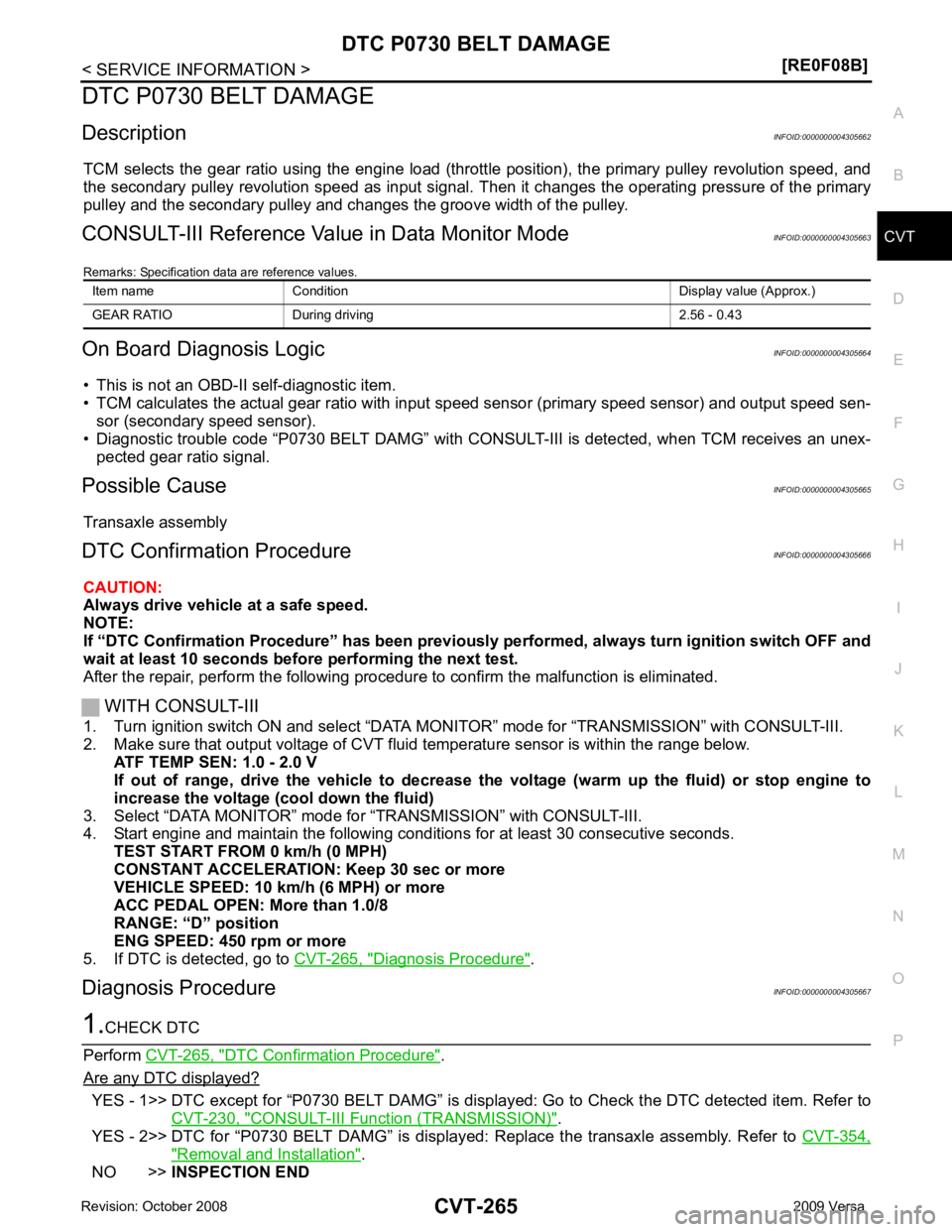
DTC P0730 BELT DAMAGE
Description INFOID:0000000004305662
TCM selects the gear ratio using the engine load (throttle position), the primary pulley revolution speed, and
the secondary pulley revolution speed as input signal. T hen it changes the operating pressure of the primary
pulley and the secondary pulley and changes the groove width of the pulley.
CONSULT-III Reference Val ue in Data Monitor Mode INFOID:0000000004305663
Remarks: Specification data are reference values.
On Board Diagnosis Logic INFOID:0000000004305664
• This is not an OBD-II self-diagnostic item.
• TCM calculates the actual gear ratio with input speed sensor (primary speed sensor) and output speed sen-
sor (secondary speed sensor).
• Diagnostic trouble code “P0730 BELT DAMG” with CONSUL T-III is detected, when TCM receives an unex-
pected gear ratio signal.
Possible Cause INFOID:0000000004305665
Transaxle assembly
DTC Confirmation Procedure INFOID:0000000004305666
CAUTION:
Always drive vehicle at a safe speed.
NOTE:
If “DTC Confirmation Procedure” has been previously performed, alw ays turn ignition switch OFF and
wait at least 10 seconds before performing the next test.
After the repair, perform the following procedure to confirm the malfunction is eliminated.
WITH CONSULT-III
1. Turn ignition switch ON and select “DATA MO NITOR” mode for “TRANSMISSION” with CONSULT-III.
2. Make sure that output voltage of CVT fluid temperature sensor is within the range below.
ATF TEMP SEN: 1.0 - 2.0 V
If out of range, drive the vehicle to decrease the voltage (warm up the fluid) or stop engine to
increase the voltage (c ool down the fluid)
3. Select “DATA MONITOR” mode for “TRANSMISSION” with CONSULT-III.
4. Start engine and maintain the following conditions for at least 30 consecutive seconds.
TEST START FROM 0 km/h (0 MPH)
CONSTANT ACCELERATION: Keep 30 sec or more
VEHICLE SPEED: 10 km/h (6 MPH) or more
ACC PEDAL OPEN: More than 1.0/8
RANGE: “D” position
ENG SPEED: 450 rpm or more
5. If DTC is detected, go to CVT-265, " Diagnosis Procedure " .
Diagnosis Procedure INFOID:0000000004305667DTC Confirmation Procedure " .
Are any DTC displayed? YES - 1>> DTC except for “P0730 BELT DAMG” is displa
yed: Go to Check the DTC detected item. Refer to
CVT-230, " CONSULT-III Function (TRANSMISSION) " .
YES - 2>> DTC for “P0730 BELT DAMG” is displayed: Replace the transaxle assembly. Refer to CVT-354," Removal and Installation " .
NO >> INSPECTION END
Item name Condition Display value (Approx.)
GEAR RATIO During driving 2.56 - 0.43
Page 1216 of 4331
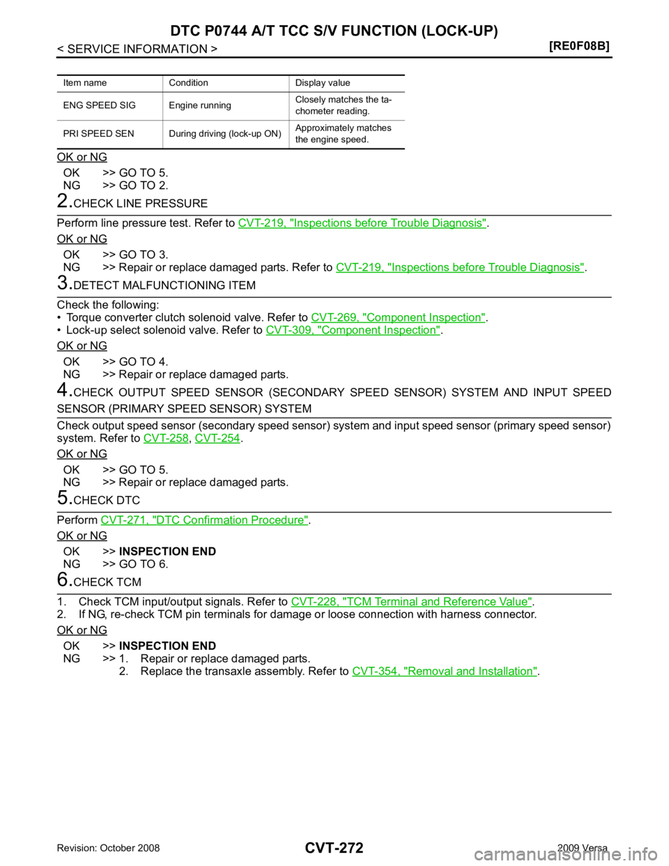
OK >> GO TO 5.
NG >> GO TO 2. Inspections before Trouble Diagnosis " .
OK or NG OK >> GO TO 3.
NG >> Repair or replace damaged parts. Refer to CVT-219, " Inspections before Trouble Diagnosis " .
Component Inspection " .
• Lock-up select solenoid valve. Refer to CVT-309, " Component Inspection " .
OK or NG OK >> GO TO 4.
NG >> Repair or replace damaged parts.
4. CHECK OUTPUT SPEED SENSOR (SECONDARY SPEED SENSOR) SYSTEM AND INPUT SPEED ,
CVT-254 .
OK or NG OK >> GO TO 5.
NG >> Repair or replace damaged parts. DTC Confirmation Procedure " .
OK or NG OK >>
INSPECTION END
NG >> GO TO 6. TCM Terminal and Reference Value " .
2. If NG, re-check TCM pin terminals for damage or loose connection with harness connector.
OK or NG OK >>
INSPECTION END
NG >> 1. Repair or replace damaged parts. 2. Replace the transaxle assembly. Refer to CVT-354, " Removal and Installation " .
Item name Condition Display value
ENG SPEED SIG Eng ine runningClosely matches the ta-
chometer reading.
PRI SPEED SEN During driving (lock-up ON) Approximately matches
the engine speed.
Page 1223 of 4331
CVT
N
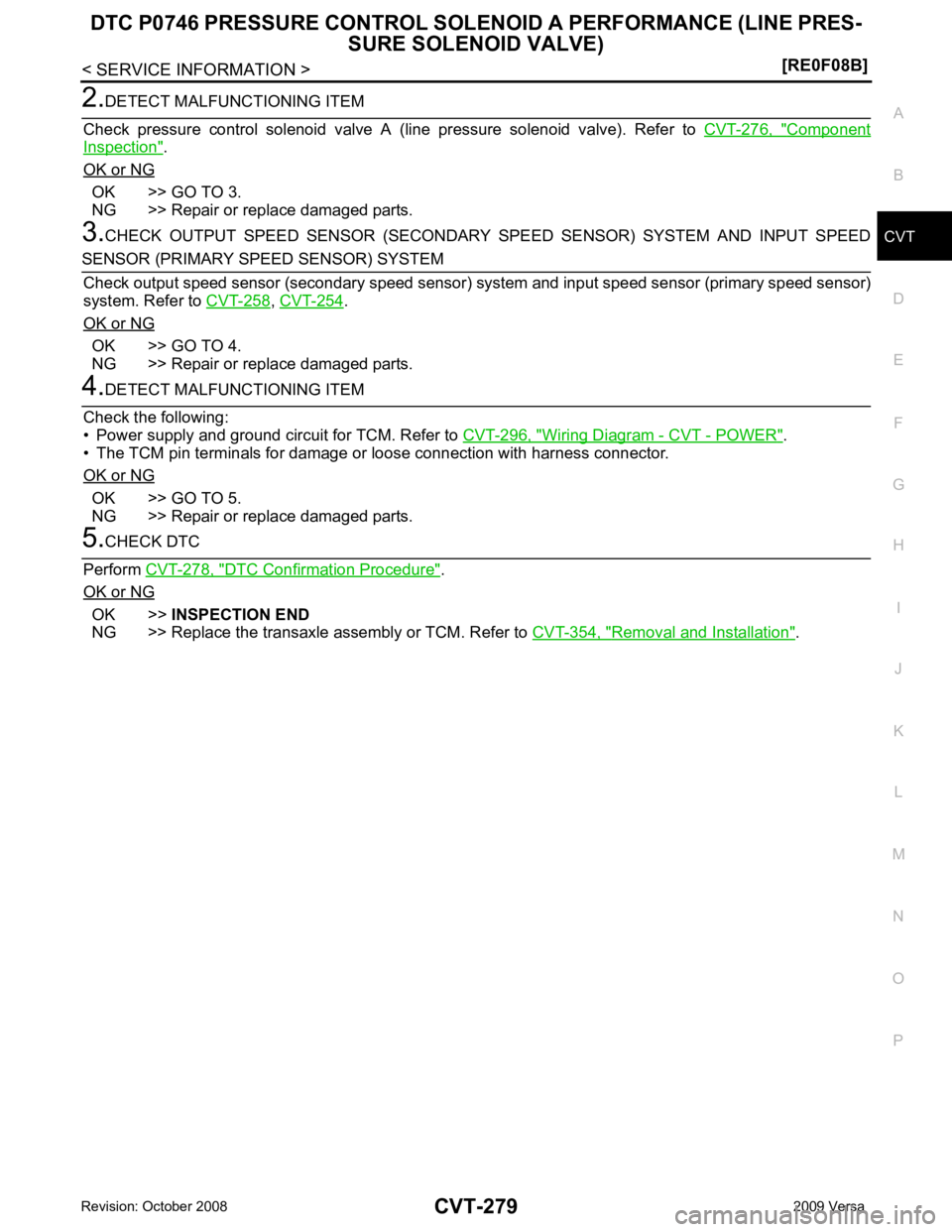
O P Component
Inspection " .
OK or NG OK >> GO TO 3.
NG >> Repair or replace damaged parts.
3. CHECK OUTPUT SPEED SENSOR (SECONDARY SPEED SENSOR) SYSTEM AND INPUT SPEED ,
CVT-254 .
OK or NG OK >> GO TO 4.
NG >> Repair or replace damaged parts. Wiring Diagram - CVT - POWER " .
• The TCM pin terminals for damage or loose connection with harness connector.
OK or NG OK >> GO TO 5.
NG >> Repair or replace damaged parts. DTC Confirmation Procedure " .
OK or NG OK >>
INSPECTION END
NG >> Replace the transaxle assembly or TCM. Refer to CVT-354, " Removal and Installation " .
Page 1225 of 4331
CVT
N
O P
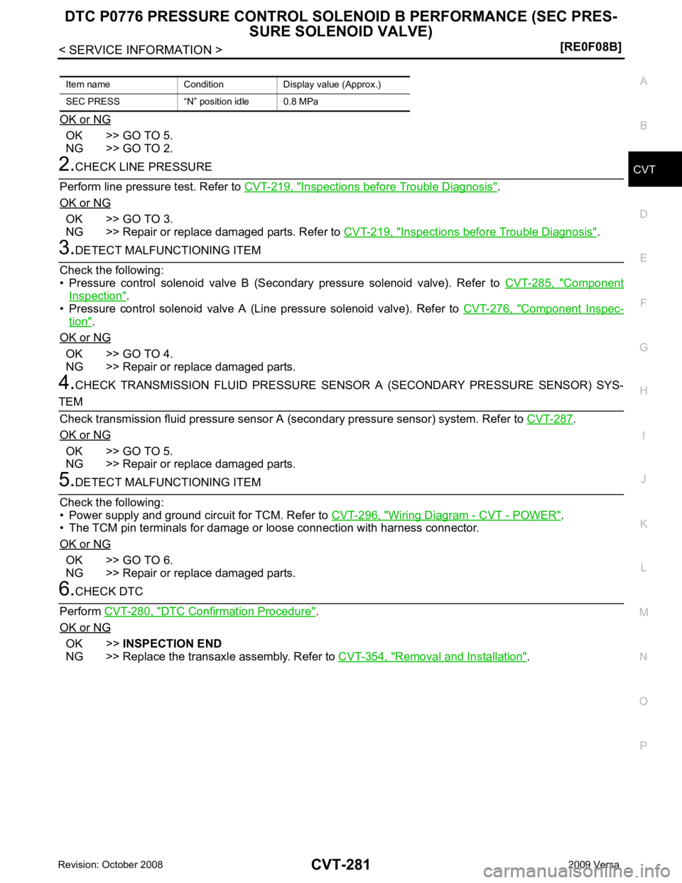
OK or NG OK >> GO TO 5.
NG >> GO TO 2. Inspections before Trouble Diagnosis " .
OK or NG OK >> GO TO 3.
NG >> Repair or replace damaged parts. Refer to CVT-219, " Inspections before Trouble Diagnosis " .
Component
Inspection " .
• Pressure control solenoid valve A (Line pressure solenoid valve). Refer to CVT-276, " Component Inspec-
tion " .
OK or NG OK >> GO TO 4.
NG >> Repair or replace damaged parts.
4. CHECK TRANSMISSION FLUID PRESSURE SENSOR A (SECONDARY PRESSURE SENSOR) SYS- .
OK or NG OK >> GO TO 5.
NG >> Repair or replace damaged parts. Wiring Diagram - CVT - POWER " .
• The TCM pin terminals for damage or loose connection with harness connector.
OK or NG OK >> GO TO 6.
NG >> Repair or replace damaged parts. DTC Confirmation Procedure " .
OK or NG OK >>
INSPECTION END
NG >> Replace the transaxle assembly. Refer to CVT-354, " Removal and Installation " .
Item name Condition Display value (Approx.)
SEC PRESS “N” position idle 0.8 MPa
Page 1231 of 4331
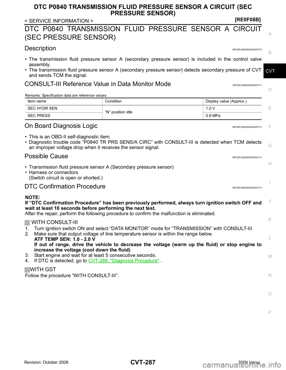
CVT
N
O P
DTC P0840 TRANSMISSION FLUID
PRESSURE SENSOR A CIRCUIT
(SEC PRESSURE SENSOR)
Description INFOID:0000000004305710
• The transmission fluid pressure sensor A (secondary pressure sensor) is included in the control valve
assembly.
• The transmission fluid pressure sensor A (secondary pressure sensor) detects secondary pressure of CVT
and sends TCM the signal.
CONSULT-III Reference Val ue in Data Monitor Mode INFOID:0000000004305711
Remarks: Specification data are reference values.
On Board Diagnosis Logic INFOID:0000000004305712
• This is an OBD-II self-diagnostic item.
• Diagnostic trouble code “P0840 TR PRS SENS/A CIRC” with CONSULT-III is detected when TCM detects
an improper voltage drop when it receives the sensor signal.
Possible Cause INFOID:0000000004305713
• Transmission fluid pressure sensor A (Secondary pressure sensor)
• Harness or connectors (Switch circuit is open or shorted.)
DTC Confirmation Procedure INFOID:0000000004305714
NOTE:
If “DTC Confirmation Procedure” has been previously performed, alw ays turn ignition switch OFF and
wait at least 10 seconds before performing the next test.
After the repair, perform the following procedure to confirm the malfunction is eliminated.
WITH CONSULT-III
1. Turn ignition switch ON and select “DATA MO NITOR” mode for “TRANSMISSION” with CONSULT-III.
2. Make sure that output voltage of line te mperature sensor is within the range below.
ATF TEMP SEN: 1.0 - 2.0 V
If out of range, drive the vehicle to decrease the voltage (warm up the fluid) or stop engine to
increase the voltage (c ool down the fluid)
3. Start engine and wait for at least 5 consecutive seconds.
4. If DTC is detected, go to CVT-289, " Diagnosis Procedure " .
WITH GST
Follow the procedure “WITH CONSULT-III”. Item name Condition Display value (Approx.)
SEC HYDR SEN “N” position idle 1.0 V
SEC PRESS 0.8 MPa
Page 1233 of 4331
![NISSAN LATIO 2009 Service Repair Manual DTC P0840 TRANSMISSION FLUID PR
ESSURE SENSOR A CIRCUIT (SEC
PRESSURE SENSOR)
CVT-289
< SERVICE INFORMATION >
[RE0F08B] D
E
F
G H
I
J
K L
M A
B CVT
N
O P
Diagnosis Procedure
INFOID:00000000043057161. NISSAN LATIO 2009 Service Repair Manual DTC P0840 TRANSMISSION FLUID PR
ESSURE SENSOR A CIRCUIT (SEC
PRESSURE SENSOR)
CVT-289
< SERVICE INFORMATION >
[RE0F08B] D
E
F
G H
I
J
K L
M A
B CVT
N
O P
Diagnosis Procedure
INFOID:00000000043057161.](/img/5/57359/w960_57359-1232.png)
DTC P0840 TRANSMISSION FLUID PR
ESSURE SENSOR A CIRCUIT (SEC
PRESSURE SENSOR)
CVT-289
< SERVICE INFORMATION >
[RE0F08B] D
E
F
G H
I
J
K L
M A
B CVT
N
O P
Diagnosis Procedure
INFOID:00000000043057161.
CHECK INPUT SIGNAL
With CONSULT-III
1. Start engine.
2. Select “ECU INPUT SIGNALS” in “DATA MONITO R” mode for “TRANSMISSION” with CONSULT-III.
3. Start vehicle and read out the value of “SEC HYDR SEN”.
Without CONSULT-III
1. Start engine.
2. Check voltage between TCM connector terminal and ground.
OK or NG OK >> GO TO 5.
NG >> GO TO 2. 2.
CHECK SENSOR POWER AND SENSOR GROUND
1. Turn ignition switch ON. (Do not start engine)
2. Check voltage between TCM connector terminals.
OK or NG OK >> GO TO 4.
NG >> GO TO 3.
3. CHECK HARNESS BETWEEN TCM AND CVT UNI T HARNESS CONNECTOR (SENSOR POWER ANDSENSOR GROUND)
1. Turn ignition switch OFF.
2. Disconnect TCM connector and CVT unit harness connector.
3. Check continuity between TCM connector terminals and CVT unit harness connector terminals.
4. If OK, check harness for short to ground and short to power.
5. Reinstall any part removed.
OK or NG Item name Condition Display value (Approx.)
SEC HYDR SEN “N” position idle 1.0 V Name Connector Terminal Condition
Voltage
(Approx.)
Transmission
fluid pressure
sensor A
(Secondary
pressure sen-
sor) E32 37 - Ground “N” position idle 1.0 V SCIA4508E
Item Connector Terminal
Data (Ap-
prox.)
TCM connector E32 46 - 42 5.0 V SCIA2367E
Item Connector Terminal Continuity
TCM E32 42 Yes
CVT unit harness connector F46 19
TCM E32 46 Yes
CVT unit harness connector F46 20 SCIA4681E
Page 1234 of 4331
![NISSAN LATIO 2009 Service Repair Manual CVT-290< SERVICE INFORMATION >
[RE0F08B]
DTC P0840 TRANSMISSION FLUID PR
ESSURE SENSOR A CIRCUIT (SEC
PRESSURE SENSOR)
OK >> Replace TCM. Refer to CVT-190, " Service After Replacing TCM and Transax NISSAN LATIO 2009 Service Repair Manual CVT-290< SERVICE INFORMATION >
[RE0F08B]
DTC P0840 TRANSMISSION FLUID PR
ESSURE SENSOR A CIRCUIT (SEC
PRESSURE SENSOR)
OK >> Replace TCM. Refer to CVT-190, " Service After Replacing TCM and Transax](/img/5/57359/w960_57359-1233.png)
CVT-290< SERVICE INFORMATION >
[RE0F08B]
DTC P0840 TRANSMISSION FLUID PR
ESSURE SENSOR A CIRCUIT (SEC
PRESSURE SENSOR)
OK >> Replace TCM. Refer to CVT-190, " Service After Replacing TCM and Transaxle Assembly " .
NG >> Repair open circuit or short to ground or short to power in harness or connectors.
4. CHECK HARNESS BETWEEN TCM AND TRANSMISSI ON FLUID PRESSURE SENSOR A (SECOND-ARY PRESSURE SENSOR)
1. Turn ignition switch OFF.
2. Disconnect TCM connector and CVT unit harness connector.
3. Check continuity between TCM connector terminal and CVT unit
harness connector terminal.
4. If OK, check harness for short to ground and short to power.
5. Reinstall any part removed.
OK or NG OK >> GO TO 5.
NG >> Repair open circuit or short to ground or short to power in harness or connectors. 5.
CHECK DTC
Perform CVT-287, " DTC Confirmation Procedure " .
OK or NG OK >>
INSPECTION END
NG >> GO TO 6. 6.
CHECK TCM
1. Check TCM input/output signals. Refer to CVT-228, " TCM Terminal and Reference Value " .
2. If NG, re-check TCM pin terminals for damage or loose connection with harness connector.
OK or NG OK >> Replace the transaxle assembly. Refer to
CVT-354, " Removal and Installation " .
NG >> Repair or replace damaged parts. Item Connector Terminal Continuity
TCM E32 37 Yes
CVT unit harness connector F46 23 SCIA4690E