sensor NISSAN LATIO 2009 Service Repair Manual
[x] Cancel search | Manufacturer: NISSAN, Model Year: 2009, Model line: LATIO, Model: NISSAN LATIO 2009Pages: 4331, PDF Size: 58.04 MB
Page 4252 of 4331
![NISSAN LATIO 2009 Service Repair Manual DTC C1601
BATTERY VOLT "
TORQUE SENSOR
[C1604] When the torque sensor malfunction assembled in steering column
assembly is detected. STC-15, " DTC C1604
TORQUE SENSOR "
EPS MOTOR
[C1606] When the NISSAN LATIO 2009 Service Repair Manual DTC C1601
BATTERY VOLT "
TORQUE SENSOR
[C1604] When the torque sensor malfunction assembled in steering column
assembly is detected. STC-15, " DTC C1604
TORQUE SENSOR "
EPS MOTOR
[C1606] When the](/img/5/57359/w960_57359-4251.png)
DTC C1601
BATTERY VOLT "
TORQUE SENSOR
[C1604] When the torque sensor malfunction assembled in steering column
assembly is detected. STC-15, " DTC C1604
TORQUE SENSOR "
EPS MOTOR
[C1606] When the motor driver
malfunction of EPS control unit or EPS motor
malfunction is detected. STC-16, " DTC C1606
EPS MOTOR "
EEPROM
[C1607] When the memory (EEPROM) system malfunction is detected in
EPS control unit. STC-17, " DTC C1607
EEPROM "
CONTROL UNIT
[C1608] When the internal malfunction is detected in EPS control unit. STC-17, " DTC C1608
CONTROL UNIT "
CAN VHCL SPEED
[C1609] When the malfunction is detected in vehicle speed signal received
with CAN communication. STC-18, " DTC C1609
CAN VHCL SPEED "
CAN ENG RPM
[C1610] When the malfunction is detected in engine status signal received
with CAN communication. STC-19, " DTC C1610
CAN ENG RPM "
CAN COMM CIRCUIT
[U1000] When EPS control unit is
not transmitting or receiving CAN commu-
nication signal 2 seconds or more. STC-19, " DTC U1000
CAN COMM CIRCUIT "
NO DTC IS DETECTED.
FURTHER TESTING MAY BE RE-
QUIRED. No NG item has been detected. —Monitor item (Unit) Remarks
MOTOR VOL (V) Power supply voltage for EPS control unit is displayed
TORQUE SENSOR (Nm) Steering wheel turning force detected by torque sensor is displayed
MOTOR SIG (A) Current commanded value to EPS motor is displayed
MOTOR CURRENT (A) Current value cons umed by EPS motor is displayed
VEHICLE SPEED (km/h) or (mph) Vehicle speed is displayed from vehicle speed signal with CAN communication
WARNING LAMP (ON/OFF) EPS warning la mp control status is displayed
DERATING STAT (ON/OFF) Protect overload status is displayed
ENGINE STATUS (STOP/RUN) Engine spee d is displayed from engine status signal with CAN communication
Page 4253 of 4331
STC
N
O P
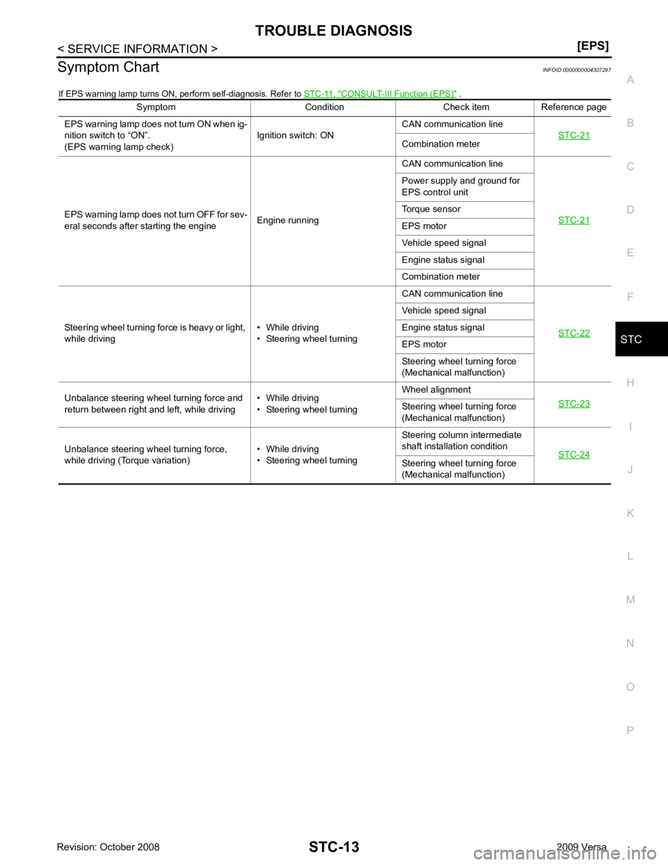
Symptom Chart
INFOID:0000000004307297
If EPS warning lamp turns ON, perform self-diagnosis. Refer to STC-11, " CONSULT-III Function (EPS) " .
Symptom Condition Check item Reference page
EPS warning lamp does not turn ON when ig-
nition switch to “ON”.
(EPS warning lamp check) Ignition switch: ONCAN communication line
STC-21 Combination meter
EPS warning lamp does not turn OFF for sev-
eral seconds after starting the engine Engine runningCAN communication line
STC-21 Power supply and ground for
EPS control unit
Torque sensor
EPS motor
Vehicle speed signal
Engine status signal
Combination meter
Steering wheel turning force is heavy or light,
while driving • While driving
• Steering wheel turning CAN communication line
STC-22 Vehicle speed signal
Engine status signal
EPS motor
Steering wheel turning force
(Mechanical malfunction)
Unbalance steering wheel turning force and
return between right and left, while driving • While driving
• Steering wheel turning Wheel alignment
STC-23 Steering wheel
turning force
(Mechanical malfunction)
Unbalance steering wheel turning force,
while driving (Torque variation) • While driving
• Steering wheel turning Steering column intermediate
shaft installation condition STC-24 Steering wheel
turning force
(Mechanical malfunction)
Page 4255 of 4331
STC
N
O P
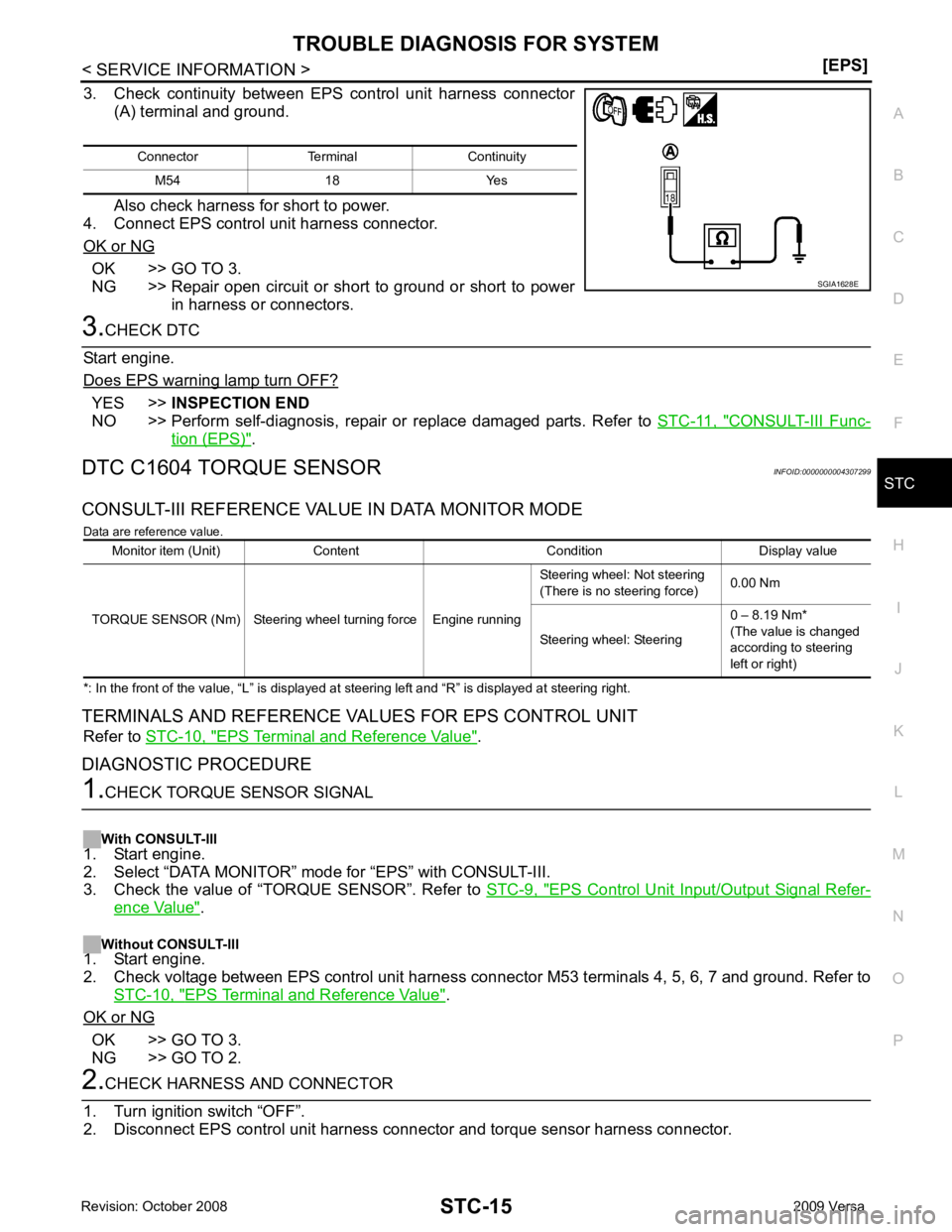
3. Check continuity between EPS control unit harness connector
(A) terminal and ground.
Also check harness for short to power.
4. Connect EPS control unit harness connector.
OK or NG OK >> GO TO 3.
NG >> Repair open circuit or short to ground or short to power
in harness or connectors. YES >>
INSPECTION END
NO >> Perform self-diagnosis, repair or replace damaged parts. Refer to STC-11, " CONSULT-III Func-
tion (EPS) " .
DTC C1604 TORQUE SENSOR INFOID:0000000004307299
CONSULT-III REFERENCE VALUE IN DATA MONITOR MODE Data are reference value.
*: In the front of the value, “L” is displayed at steering left and “R” is displayed at steering right.
TERMINALS AND REFERENCE VA LUES FOR EPS CONTROL UNIT
Refer to STC-10, " EPS Terminal and Reference Value " .
DIAGNOSTIC PROCEDURE EPS Control Unit Input/Output Signal Refer-
ence Value " .
Without CONSULT-III
1. Start engine.
2. Check voltage between EPS control unit harness connec tor M53 terminals 4, 5, 6, 7 and ground. Refer to
STC-10, " EPS Terminal and Reference Value " .
OK or NG OK >> GO TO 3.
NG >> GO TO 2.
Page 4256 of 4331
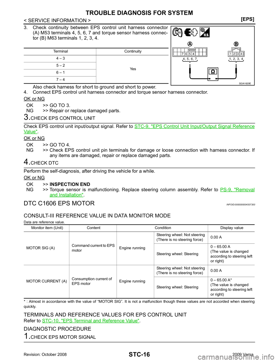
OK >> GO TO 3.
NG >> Repair or replace damaged parts. EPS Control Unit Input/Output Signal Reference
Value " .
OK or NG OK >> GO TO 4.
NG >> Check EPS control unit pin terminals for dam age or loose connection with harness connector. If
any items are damaged, repair or replace damaged parts. OK >>
INSPECTION END
NG >> Torque sensor is malfunctioning. Replace steering column assembly. Refer to PS-9, " Removal
and Installation " .
DTC C1606 EPS MOTOR INFOID:0000000004307300
CONSULT-III REFERENCE VALUE IN DATA MONITOR MODE
Data are reference value.
* : Almost in accordance with the value of “MOTOR SIG”. It is not a malfunction though these values are not accorded when steer ing
quickly.
TERMINALS AND REFERENCE VALUES FOR EPS CONTROL UNIT
Refer to STC-10, " EPS Terminal and Reference Value " .
DIAGNOSTIC PROCEDURE
Page 4274 of 4331

WT
N
O P
A sensor-transmitter integrated with a valve is installed in each
wheel, and transmits a detected air pressure signal in the form of a
radio wave. The radio signal is received by the remote keyless entry
receiver.
REMOTE KEYLESS ENTRY RECEIVER The remote keyless entry receiver is shown with the glove box
removed. The remote keyless entry receiver receives the air pres-
sure signal transmitted by the transmitter in each wheel.
COMBINATION METER The combination meter receives tire pressure status from the BCM
using CAN communication. When a low tire pressure condition is
sensed by the BCM, the combination meter low tire pressure warn-
ing lamp is activated.
TIRE PRESSURE WARNING CHECK CONNECTOR The tire pressure warning check connector can be grounded in order to initiate self-diagnosis without a CON-
SULT-III. Refer to WT-17, " Self-Diagnosis (Without CONSULT-III) " . The tire pressure warning check connector
is located behind the lower portion of the instrument panel LH. Refer to PG-38, " Harness Layout " . WEIA0186E
LEIA0055E
Page 4284 of 4331
WT
N
O P
TROUBLE DIAGNOSIS FOR
SELF-DIAGNOSTIC ITEMS
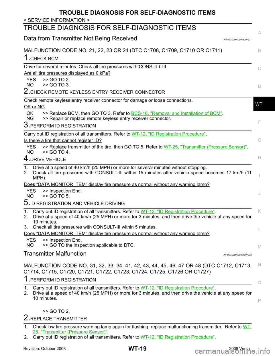
Data from Transmitter Not Being Received INFOID:0000000004307331
MALFUNCTION CODE NO. 21, 22 , 23 OR 24 (DTC C1708, C1709, C1710 OR C1711)YES >> GO TO 2.
NO >> GO TO 3. OK >> Replace BCM, then GO TO 3. Refer to
BCS-18, " Removal and Installation of BCM " .
NG >> Repair or replace remote keyless entry receiver connector. ID Registration Procedure " .
Is there a tire that cannot register ID? YES >> Replace transmitter of the
tire, then GO TO 5. Refer to WT-25, " Transmitter (Pressure Sensor) " .
NO >> GO TO 4. “ DATA MONITOR ITEM ” display tire pressure as normal without any warning lamp?
YES >> Inspection End.
NO >> GO TO 5. ID Registration Procedure " .
2. Drive at a speed of 40 km/h (25 MPH) or more fo r 3 minutes, and then drive the vehicle at any speed for
10 minutes.
3. Check all tire pressures with CONSULT-III within 5 minutes.
Does “ DATA MONITOR ITEM ” display tire pressure as normal without any warning lamp?
YES >> Inspection End.
NO >> GO TO the inspection applicable to DTC.
Transmitter Malfunction INFOID:0000000004307332
MALFUNCTION CODE NO. 31, 32, 33 , 34, 41, 42, 43, 44, 45, 46, 47 OR 48 (DTC C1712, C1713,
C1714, C1715, C1720, C1721, C1722, C1723, C1724, C1725, C1726 OR C1727) ID Registration Procedure " .
2. Drive at a speed of 40 km/h (25 MPH) or more fo r 3 minutes, and then drive the vehicle at any speed for
10 minutes.
>> GO TO 2. 25, " Transmitter (Pressure Sensor) " .
2. Carry out ID registration of all transmitters. Refer to WT-12, " ID Registration Procedure " .
Page 4285 of 4331
YES >> GO TO 3.
NO >> GO TO WT-19, " Data from Transmitter Not Being Received " .
“ DATA MONITOR ITEM ” display tire pressure as normal without any warning lamp?
YES >> Inspection End.
NO >> Replace malfunctioning transmitter, and perform Step 3 again. Refer to WT-25, " Transmitter
(Pressure Sensor) " .
Transmitter Pressure Malfunction INFOID:0000000004307333
MALFUNCTION CODE NO. 35, 36, 37 OR 38 (DTC C1716, C1717, C1718 OR C1719) Tire " .
Are there any tires with pressure of 64 psi or more? YES >> Adjust tire pressure to specified value.
NO >> GO TO 2. ID Registration Procedure " .
2. Drive at a speed of 40 km/h (25 MPH) or more for several minutes without stopping.
3. Check all tire pressures with CONSULT-III within 15 minutes after vehicle speed becomes 17 km/h (11
MPH).
Does “ DATA MONITOR ITEM ” display 64 psi or more?
YES >> Replace transmitter. Refer to
WT-25, " Transmitter (Pressure Sensor) " . GO TO 3.
NO >> GO TO 3. ID Registration Procedure " .
2. Drive at a speed of 40 km/h (25 MPH) or more fo r 3 minutes, and then drive the vehicle at any speed for
10 minutes.
3. Check all tire pressures with CONSULT-III within 5 minutes.
Does “ DATA MONITOR ITEM ” display tire pressure as normal without any warning lamp?
YES >> Inspection End.
NO >> GO TO the inspection applicable to DTC.
Vehicle Speed Signal INFOID:0000000004307334
MALFUNCTION CODE NO. 52 (DTC C1729) YES >> Malfunction in CAN communication system. GO TO
LAN-14, " CAN Diagnosis with CONSULT-III " .
NO >> GO TO 2. CONSULT-III Function (BCM) " .
Inspection results OK? OK >> Perform Vehicle Speed Sensor Inspection. Refer to
EC-1388, " Diagnosis Procedure " .
NG >> Replace BCM. Refer to BCS-18, " Removal and Installation of BCM " .
Page 4290 of 4331
WT
N
O P
REMOVAL AND INSTALLATION
Transmitter (Pressure Sensor) INFOID:0000000004307341
REMOVAL 1. Remove wheel and tire using power tool.
2. Deflate tire. Unscrew transmitter retaining nut and allow transmitter to fall into tire.
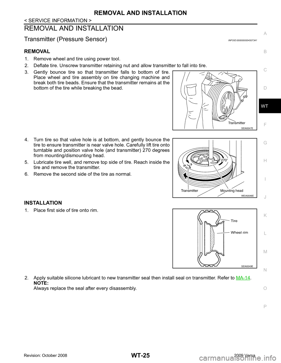
3. Gently bounce tire so that transmitter falls to bottom of tire. Place wheel and tire assembly on tire changing machine and
break both tire beads. Ensure that the transmitter remains at the
bottom of the tire while breaking the bead.
4. Turn tire so that valve hole is at bottom, and gently bounce the tire to ensure transmitter is near valve hole. Carefully lift tire onto
turntable and position valve hole (and transmitter) 270 degrees
from mounting/dismounting head.
5. Lubricate tire well, and remove top side of tire. Reach inside the tire and remove the transmitter.
6. Remove the second side of the tire as normal.
INSTALLATION 1. Place first side of tire onto rim.
2. Apply suitable silicone lubricant to new transmitter seal then install seal on transmitter. Refer to MA-14 .
NOTE:
Always replace the seal after every disassembly.
Page 4315 of 4331
WW
N
O P
Removal and Installation of
Front Wiper and Washer Switch INFOID:0000000004306930
REMOVAL 1. Remove the steering column cover. Refer to IP-11 .
2. Disconnect the wiper and washer switch connector.
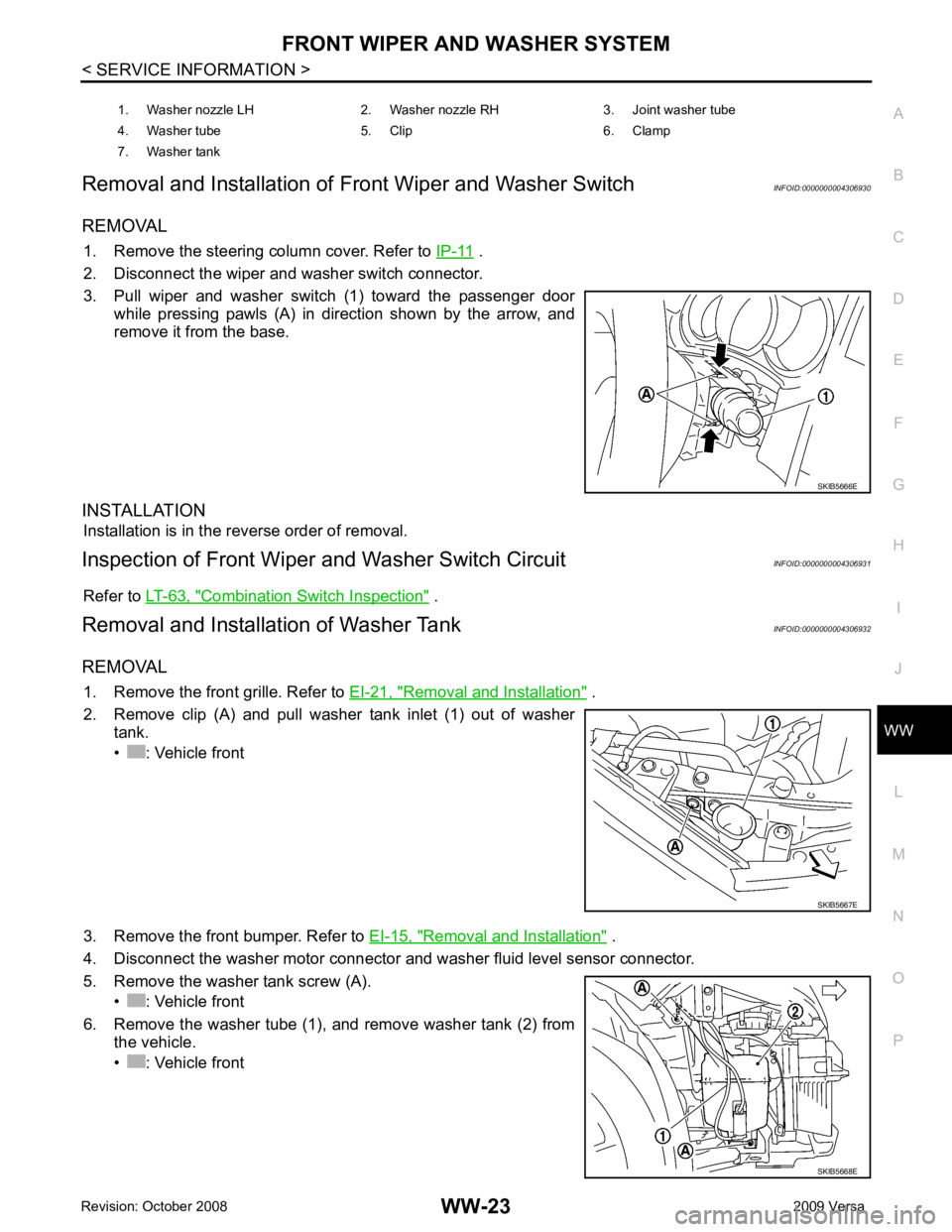
3. Pull wiper and washer switch (1) toward the passenger door while pressing pawls (A) in direction shown by the arrow, and
remove it from the base.
INSTALLATION Installation is in the reverse order of removal.
Inspection of Front Wiper and Washer Switch Circuit INFOID:0000000004306931
Refer to LT-63, " Combination Switch Inspection " .
Removal and Installation of Washer Tank INFOID:0000000004306932
REMOVAL 1. Remove the front grille. Refer to EI-21, " Removal and Installation " .
2. Remove clip (A) and pull washer tank inlet (1) out of washer tank.
• : Vehicle front
3. Remove the front bumper. Refer to EI-15, " Removal and Installation " .
4. Disconnect the washer motor connector and washer fluid level sensor connector.
5. Remove the washer tank screw (A). • : Vehicle front
6. Remove the washer tube (1), and remove washer tank (2) from the vehicle.
• : Vehicle front 1. Washer nozzle LH 2. Washer nozzle RH 3. Joint washer tube
4. Washer tube 5. Clip 6. Clamp
7. Washer tank