NISSAN LATIO 2009 Service Repair Manual
Manufacturer: NISSAN, Model Year: 2009, Model line: LATIO, Model: NISSAN LATIO 2009Pages: 4331, PDF Size: 58.04 MB
Page 1861 of 4331

EC
NP
O
SERVICE INFOMATION
APPLICATION NOTICE
How to Check Vehicle Type INFOID:0000000004539412
Check the vehicle serial number to confi rm the service information in EC section.
Vehicle serial number Service information
Up to serial 386333 MR TYPE 1
From serial 386334 MR TYPE 2
Page 1862 of 4331
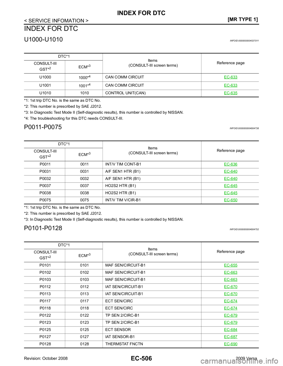
U1001
1001*4
CAN COMM CIRCUIT EC-633U1010 1010 CONTROL UNIT(CAN)
EC-635DTC*1
Items
(CONSULT-III screen terms) Reference page
CONSULT-III
GST* 2
ECM*3
P0011 0011 INT/V TIM CONT-B1 EC-636P0031 0031 A/F SEN1 HTR (B1)
EC-640P0032 0032 A/F SEN1 HTR (B1)
EC-640P0037 0037 HO2S2 HTR (B1)
EC-645P0038 0038 HO2S2 HTR (B1)
EC-645P0075 0075 INT/V TIM V/CIR-B1
EC-650DTC*1
Items
(CONSULT-III screen terms) Reference page
CONSULT-III
GST* 2
ECM*3
P0101 0101 MAF SEN/CIRCUIT-B1 EC-655P0102 0102 MAF SEN/CIRCUIT-B1
EC-663P0103 0103 MAF SEN/CIRCUIT-B1
EC-663P0112 0112 IAT SEN/CIRCUIT-B1
EC-670P0113 0113 IAT SEN/CIRCUIT-B1
EC-670P0117 0117 ECT SEN/CIRC
EC-674P0118 0118 ECT SEN/CIRC
EC-674P0122 0122 TP SEN 2/CIRC-B1
EC-679P0123 0123 TP SEN 2/CIRC-B1
EC-679P0125 0125 ECT SENSOR
EC-684P0127 0127 IAT SENSOR-B1
EC-687P0128 0128 THERMSTAT FNCTN
EC-690
Page 1863 of 4331
EC
NP
O
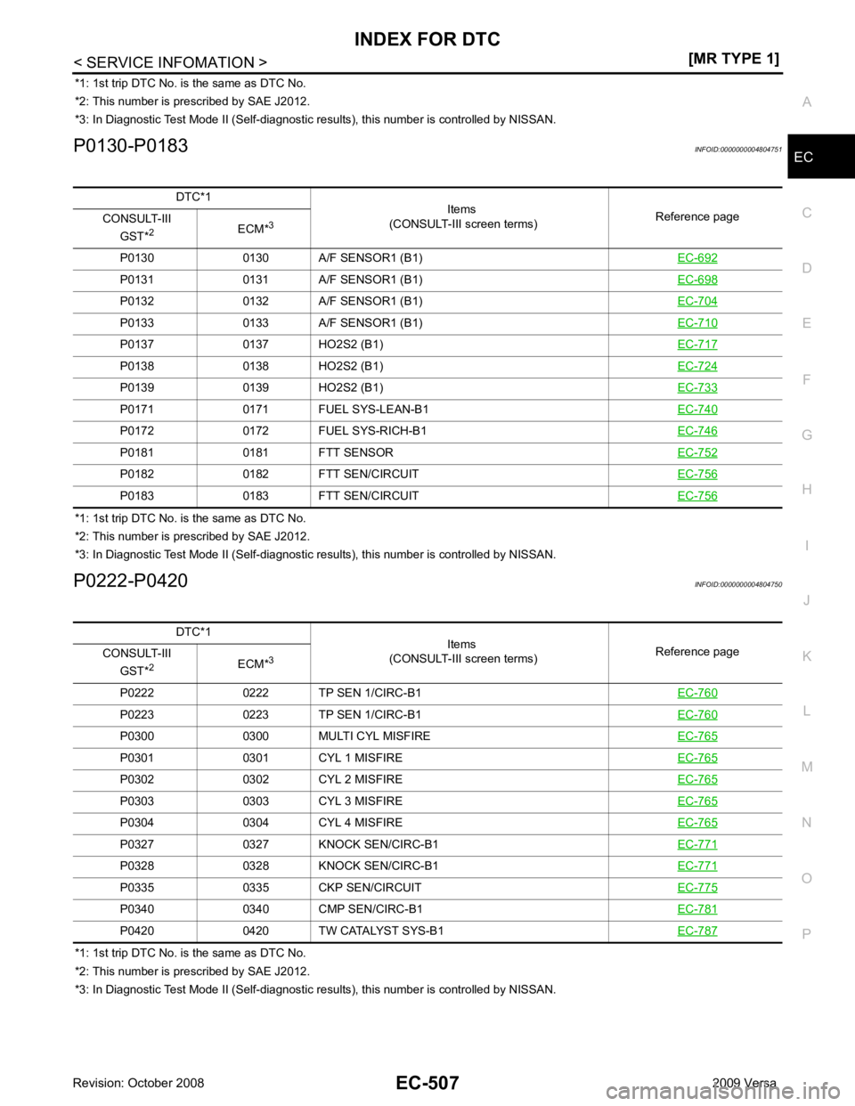
*1: 1st trip DTC No. is
the same as DTC No.
*2: This number is prescribed by SAE J2012.
*3: In Diagnostic Test Mode II (Self-diagnostic results), this number is controlled by NISSAN.
P0130-P0183 INFOID:0000000004804751
*1: 1st trip DTC No. is the same as DTC No.
*2: This number is prescribed by SAE J2012.
*3: In Diagnostic Test Mode II (Self-diagnostic results), this number is controlled by NISSAN.
P0222-P0420 INFOID:0000000004804750
*1: 1st trip DTC No. is the same as DTC No.
*2: This number is prescribed by SAE J2012.
*3: In Diagnostic Test Mode II (Self-diagnostic results), this number is controlled by NISSAN.
DTC*1
Items
(CONSULT-III screen terms) Reference page
CONSULT-III
GST* 2
ECM*3
P0130 0130 A/F SENSOR1 (B1) EC-692P0131 0131 A/F SENSOR1 (B1)
EC-698P0132 0132 A/F SENSOR1 (B1)
EC-704P0133 0133 A/F SENSOR1 (B1)
EC-710P0137 0137 HO2S2 (B1)
EC-717P0138 0138 HO2S2 (B1)
EC-724P0139 0139 HO2S2 (B1)
EC-733P0171 0171 FUEL SYS-LEAN-B1
EC-740P0172 0172 FUEL SYS-RICH-B1
EC-746P0181 0181 FTT SENSOR
EC-752P0182 0182 FTT SEN/CIRCUIT
EC-756P0183 0183 FTT SEN/CIRCUIT
EC-756DTC*1
Items
(CONSULT-III screen terms) Reference page
CONSULT-III
GST* 2
ECM*3
P0222 0222 TP SEN 1/CIRC-B1 EC-760P0223 0223 TP SEN 1/CIRC-B1
EC-760P0300 0300 MULTI CYL MISFIRE
EC-765P0301 0301 CYL 1 MISFIRE
EC-765P0302 0302 CYL 2 MISFIRE
EC-765P0303 0303 CYL 3 MISFIRE
EC-765P0304 0304 CYL 4 MISFIRE
EC-765P0327 0327 KNOCK SEN/CIRC-B1
EC-771P0328 0328 KNOCK SEN/CIRC-B1
EC-771P0335 0335 CKP SEN/CIRCUIT
EC-775P0340 0340 CMP SEN/CIRC-B1
EC-781P0420 0420 TW CATALYST SYS-B1
EC-787
Page 1864 of 4331
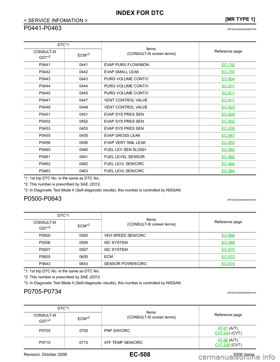
P0442 0442 EVAP SMALL LEAK
EC-797P0443 0443 PURG VOLUME CONT/V
EC-804P0444 0444 PURG VOLUME CONT/V
EC-811P0445 0445 PURG VOLUME CONT/V
EC-811P0447 0447 VENT CONTROL VALVE
EC-817P0448 0448 VENT CONTROL VALVE
EC-823P0451 0451 EVAP SYS PRES SEN
EC-829P0452 0452 EVAP SYS PRES SEN
EC-832P0453 0453 EVAP SYS PRES SEN
EC-839P0455 0455 EVAP GROSS LEAK
EC-847P0456 0456 EVAP VERY SML LEAK
EC-853P0460 0460 FUEL LEV SEN SLOSH
EC-860P0461 0461 FUEL LEVEL SENSOR
EC-862P0462 0462 FUEL LEVL SEN/CIRC
EC-864P0463 0463 FUEL LEVL SEN/CIRC
EC-864DTC*1
Items
(CONSULT-III screen terms) Reference page
CONSULT-III
GST* 2
ECM*3
P0500 0500 VEH SPEED SEN/CIRC EC-866P0506 0506 ISC SYSTEM
EC-868P0507 0507 ISC SYSTEM
EC-870P0605 0605 ECM
EC-872P0643 0643 SENSOR POWER/CIRC
EC-874DTC*1
Items
(CONSULT-III screen terms) Reference page
CONSULT-III
GST* 2
ECM*3
P0705 0705 PNP SW/CIRC AT-91 (A/T),
CVT-244 (CVT)
P0710 0710 ATF TEMP SEN/CIRC AT-96 (A/T),
CVT-249 (CVT)
Page 1865 of 4331
EC
NP
O
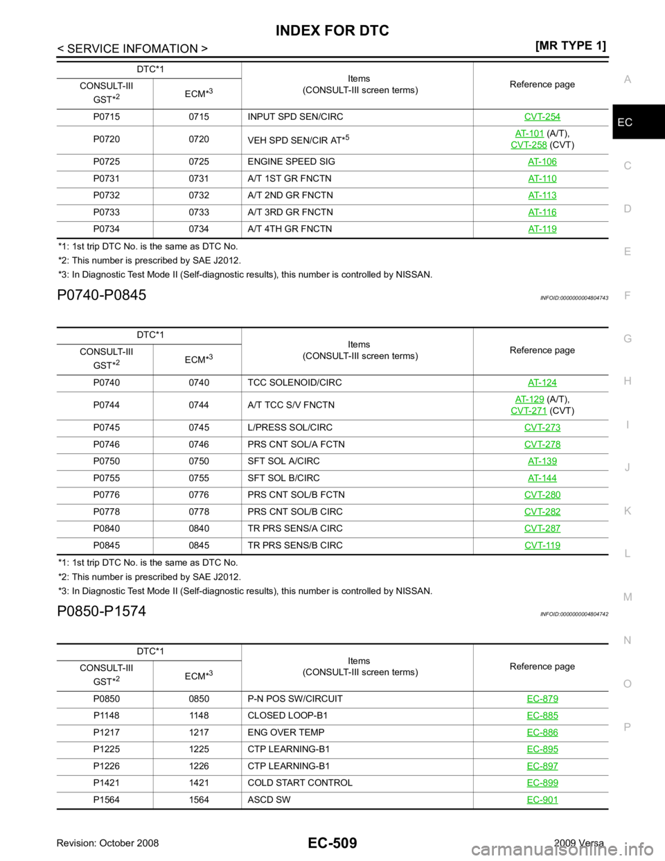
*1: 1st trip DTC No. is
the same as DTC No.
*2: This number is prescribed by SAE J2012.
*3: In Diagnostic Test Mode II (Self-diagnostic results), this number is controlled by NISSAN.
P0740-P0845 INFOID:0000000004804743
*1: 1st trip DTC No. is the same as DTC No.
*2: This number is prescribed by SAE J2012.
*3: In Diagnostic Test Mode II (Self-diagnostic results), this number is controlled by NISSAN.
P0850-P1574 INFOID:0000000004804742
P0715 0715 INPUT SPD SEN/CIRC
CVT-254P0720 0720
VEH SPD SEN/CIR AT*5
AT-101 (A/T),
CVT-258 (CVT)
P0725 0725 ENGINE SPEED SIG AT-106P0731 0731 A/T 1ST GR FNCTN
AT-110P0732 0732 A/T 2ND GR FNCTN
AT-113P0733 0733 A/T 3RD GR FNCTN
AT-116P0734 0734 A/T 4TH GR FNCTN
AT-119DTC*1
Items
(CONSULT-III screen terms) Reference page
CONSULT-III
GST* 2
ECM*3 P0744 0744 A/T TCC S/V FNCTN
AT-129 (A/T),
CVT-271 (CVT)
P0745 0745 L/PRESS SOL/CIRC CVT-273P0746 0746 PRS CNT SOL/A FCTN
CVT-278P0750 0750 SFT SOL A/CIRC
AT-139P0755 0755 SFT SOL B/CIRC
AT-144P0776 0776 PRS CNT SOL/B FCTN
CVT-280P0778 0778 PRS CNT SOL/B CIRC
CVT-282P0840 0840 TR PRS SENS/A CIRC
CVT-287P0845 0845 TR PRS SENS/B CIRC
CVT-119DTC*1
Items
(CONSULT-III screen terms) Reference page
CONSULT-III
GST* 2
ECM*3
P0850 0850 P-N POS SW/CIRCUIT EC-879P1148 1148 CLOSED LOOP-B1
EC-885P1217 1217 ENG OVER TEMP
EC-886P1225 1225 CTP LEARNING-B1
EC-895P1226 1226 CTP LEARNING-B1
EC-897P1421 1421 COLD START CONTROL
EC-899P1564 1564 ASCD SW
EC-901
Page 1866 of 4331
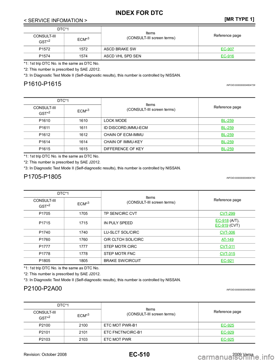
P1574 1574 ASCD VHL SPD SEN
EC-916DTC*1
Items
(CONSULT-III screen terms) Reference page
CONSULT-III
GST* 2
ECM*3 P1611 1611 ID DISCORD,IMMU-ECM
BL-259P1612 1612 CHAIN OF ECM-IMMU
BL-259P1614 1614 CHAIN OF IMMU-KEY
BL-259P1615 1615 DIFFERENCE OF KEY
BL-259DTC*1
Items
(CONSULT-III screen terms) Reference page
CONSULT-III
GST* 2
ECM*3
P1705 1705 TP SEN/CIRC CVT CVT-299P1715 1715 IN PULY SPEED
EC-918 (A/T),
EC-919 (CVT)
P1740 1740 LU-SLCT SOL/CIRC CVT-306P1760 1760 O/R CLTCH SOL/CIRC
AT-149P1777 1777 STEP MOTR CIRC
CVT-311P1778 1778 STEP MOTR FNC
CVT-315P1805 1805 BRAKE SW/CIRCUIT
EC-921DTC*1
Items
(CONSULT-III screen terms) Reference page
CONSULT-III
GST* 2
ECM*3
P2100 2100 ETC MOT PWR-B1 EC-925P2101 2101 ETC FNCTN/CIRC-B1
EC-929P2103 2103 ETC MOT PWR
EC-925
Page 1867 of 4331
EC
NP
O
*1: 1st trip DTC No. is
the same as DTC No.
*2: This number is prescribed by SAE J2012.
*3: In Diagnostic Test Mode II (Self-diagnostic results), this number is controlled by NISSAN.
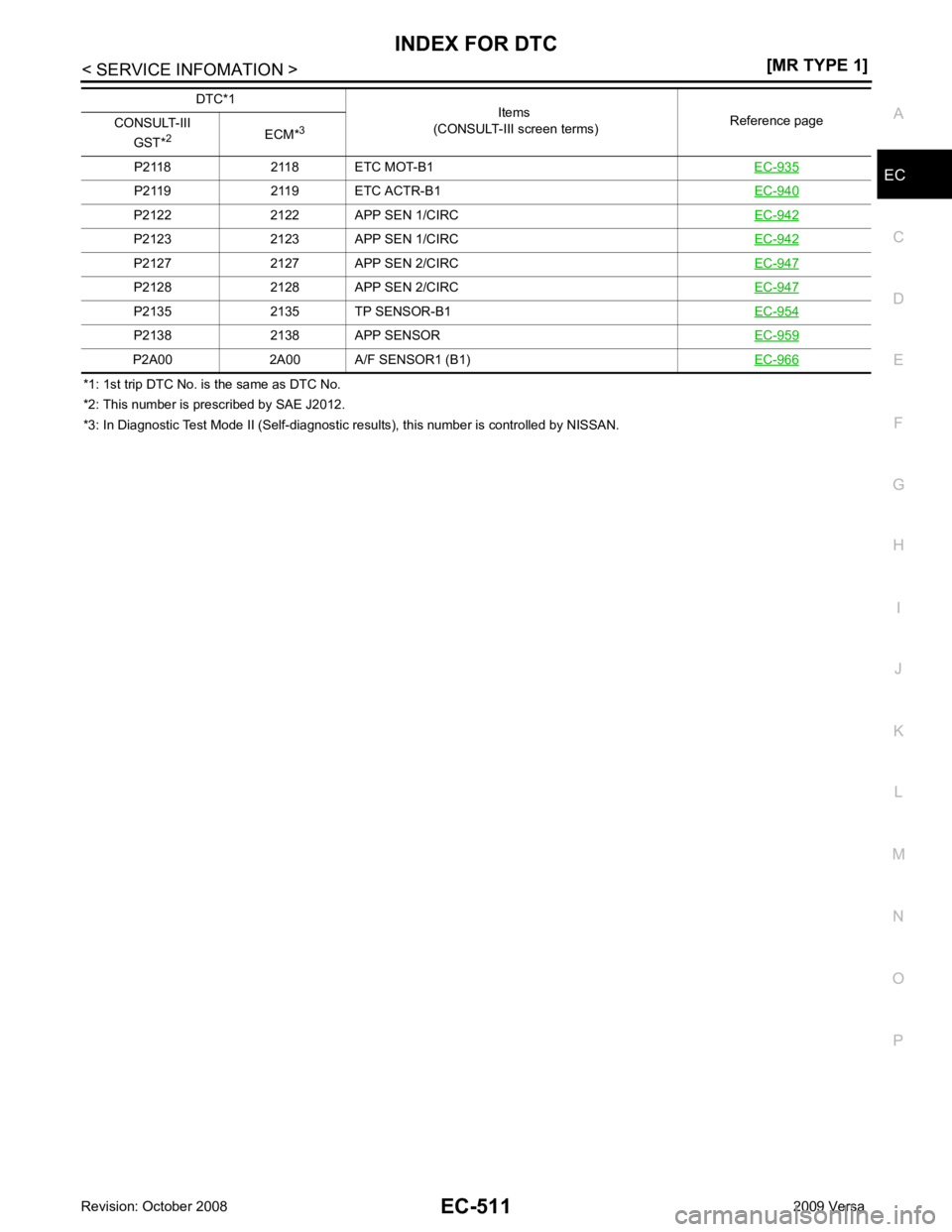
P2118 2118 ETC MOT-B1
EC-935P2119 2119 ETC ACTR-B1
EC-940P2122 2122 APP SEN 1/CIRC
EC-942P2123 2123 APP SEN 1/CIRC
EC-942P2127 2127 APP SEN 2/CIRC
EC-947P2128 2128 APP SEN 2/CIRC
EC-947P2135 2135 TP SENSOR-B1
EC-954P2138 2138 APP SENSOR
EC-959P2A00 2A00 A/F SENSOR1 (B1)
EC-966DTC*1
Items
(CONSULT-III screen terms) Reference page
CONSULT-III
GST* 2
ECM*3
Page 1868 of 4331
![NISSAN LATIO 2009 Service Repair Manual EC-512< SERVICE INFOMATION >
[MR TYPE 1]
PRECAUTIONS
PRECAUTIONS
Precaution for Supplemental Restraint Syst em (SRS) "AIR BAG" and "SEAT BELT
PRE-TENSIONER" INFOID:0000000004537013
The Supplemental NISSAN LATIO 2009 Service Repair Manual EC-512< SERVICE INFOMATION >
[MR TYPE 1]
PRECAUTIONS
PRECAUTIONS
Precaution for Supplemental Restraint Syst em (SRS) "AIR BAG" and "SEAT BELT
PRE-TENSIONER" INFOID:0000000004537013
The Supplemental](/img/5/57359/w960_57359-1867.png)
EC-512< SERVICE INFOMATION >
[MR TYPE 1]
PRECAUTIONS
PRECAUTIONS
Precaution for Supplemental Restraint Syst em (SRS) "AIR BAG" and "SEAT BELT
PRE-TENSIONER" INFOID:0000000004537013
The Supplemental Restraint System such as “A IR BAG” and “SEAT BELT PRE-TENSIONER”, used along
with a front seat belt, helps to reduce the risk or severi ty of injury to the driver and front passenger for certain
types of collision. This system includes seat belt switch inputs and dual stage front air bag modules. The SRS
system uses the seat belt switches to determine the front air bag deployment, and may only deploy one front
air bag, depending on the severity of a collision and w hether the front occupants are belted or unbelted.
Information necessary to service the system safely is included in the “SUPPLEMENTAL RESTRAINT SYS-
TEM” and “SEAT BELTS” of this Service Manual.
WARNING:
• To avoid rendering the SRS inopera tive, which could increase the risk of personal injury or death in
the event of a collision which would result in air bag inflation, all maintenance must be performed by
an authorized NISS AN/INFINITI dealer.
• Improper maintenance, including in correct removal and installation of the SRS, can lead to personal
injury caused by unintent ional activation of the system. For re moval of Spiral Cable and Air Bag
Module, see the “SUPPLEMEN TAL RESTRAINT SYSTEM”.
• Do not use electrical test equipmen t on any circuit related to the SRS unless instructed to in this
Service Manual. SRS wiring harn esses can be identified by yellow and/or orange harnesses or har-
ness connectors.
PRECAUTIONS WHEN USING POWER TOOLS (AIR OR ELECTRIC) AND HAMMERS
WARNING:
• When working near the Airbag Diagnosis Sensor Unit or other Airbag System sensors with the igni-
tion ON or engine running, DO NOT use air or electri c power tools or strike near the sensor(s) with a
hammer. Heavy vibration could activate the sensor( s) and deploy the air bag(s), possibly causing
serious injury.
• When using air or electric power tools or hammers , always switch the ignition OFF, disconnect the
battery, and wait at least 3 minu tes before performing any service.
Precaution for Procedure without Cowl Top Cover INFOID:0000000004537014
When performing the procedure after removing cowl top cover, cover
the lower end of windshield with urethane, etc.
On Board Diagnosis (OBD) Syst em of Engine and A/T, CVT INFOID:0000000004537015
The ECM has an on board diagnostic system. It will light up the malfunction indicator lamp (MIL) to warn the
driver of a malfunction causing emission deterioration.
CAUTION:
• Be sure to turn the ignition sw itch OFF and disconnect the battery ground cable before any repair or
inspection work. The open/short circuit of related sw itches, sensors, solenoid valves, etc. will cause
the MIL to light up.
• Be sure to connect and lock the connectors secure ly after work. A loose (unlocked) connector will
cause the MIL to light up due to the open circuit. (Be sure the connector is free from water, grease,
dirt, bent terminals, etc.)
• Certain systems and components, especially those related to OBD, may use a new style slide-lock-
ing type harness connector. For descrip tion and how to disconnect, refer to PG-64, " Description " .
• Be sure to route and secure the harnesses properly after work. The interference of the harness with
a bracket, etc. may cause the MIL to li ght up due to the short circuit. PIIB3706J
Page 1869 of 4331
![NISSAN LATIO 2009 Service Repair Manual PRECAUTIONS
EC-513
< SERVICE INFOMATION >
[MR TYPE 1] C
D E
F
G H
I
J
K L
M A EC
NP
O
• Be sure to connect rubber tubes properly afte
r work. A misconnected or disconnected rubber tube NISSAN LATIO 2009 Service Repair Manual PRECAUTIONS
EC-513
< SERVICE INFOMATION >
[MR TYPE 1] C
D E
F
G H
I
J
K L
M A EC
NP
O
• Be sure to connect rubber tubes properly afte
r work. A misconnected or disconnected rubber tube](/img/5/57359/w960_57359-1868.png)
PRECAUTIONS
EC-513
< SERVICE INFOMATION >
[MR TYPE 1] C
D E
F
G H
I
J
K L
M A EC
NP
O
• Be sure to connect rubber tubes properly afte
r work. A misconnected or disconnected rubber tube
may cause the MIL to light up due to the malfunction of the fuel injection system, etc.
• Be sure to erase the unnecessary malfunction informa tion (repairs completed) from the ECM and
TCM (Transmission control module) before returning the vehicle to the customer.
Precaution INFOID:0000000004537016
• Always use a 12 volt battery as power source.
• Do not attempt to disconnect battery cables while engine is
running.
• Before connecting or disc onnecting the ECM harness con-
nector, turn ignition switch OFF and disconnect negative bat-
tery cable. Failure to do so may damage the ECM because
battery voltage is applied to ECM even if ignition switch is
turned OFF.
• Before removing parts, turn ig nition switch OFF and then dis-
connect negative battery cable.
• Do not disassemble ECM.
• If battery cable is disconnected, the memory will return to the
initial ECM values.
The ECM will now start to self-c ontrol at its initial values.
Engine operation can vary slight ly in this case. However, this
is not an indication of a malf unction. Do not replace parts
because of a slight variation.
• If the battery is disconnected, the following emission-related
diagnostic information will be lost within 24 hours.
- Diagnostic trouble codes
- 1st trip diagnostic trouble codes
- Freeze frame data
- 1st trip freeze frame data
- System readiness test (SRT) codes
- Test values
• When connecting ECM harness connector, fasten (B) it
securely with a lever (1) as far as it will go as shown in the fig-
ure.
- ECM (2)
- Loosen (A)
• When connecting or disconnect ing pin connectors into or
from ECM, take care not to damage pin terminals (bend or
break).
Make sure that there are not any bends or breaks on ECM pin
terminal, when connecting pin connectors.
• Securely connect ECM harness connectors.
A poor connection can cause an extremely high (surge) volt-
age to develop in coil and cond enser, thus resulting in dam-
age to ICs.
• Keep engine control system harness at least 10 cm (4 in) away
from adjacent harness, to prevent engine control system mal-
functions due to receiving externa l noise, degraded operation
of ICs, etc. SEF289H
PBIA9222J
PBIB2947E
PBIB0090E
Page 1870 of 4331
![NISSAN LATIO 2009 Service Repair Manual EC-514< SERVICE INFOMATION >
[MR TYPE 1]
PRECAUTIONS
• Keep engine control system parts and harness dry.
• Before replacing ECM, perform “ECM Terminals and Refer-
ence Value” inspecti NISSAN LATIO 2009 Service Repair Manual EC-514< SERVICE INFOMATION >
[MR TYPE 1]
PRECAUTIONS
• Keep engine control system parts and harness dry.
• Before replacing ECM, perform “ECM Terminals and Refer-
ence Value” inspecti](/img/5/57359/w960_57359-1869.png)
EC-514< SERVICE INFOMATION >
[MR TYPE 1]
PRECAUTIONS
• Keep engine control system parts and harness dry.
• Before replacing ECM, perform “ECM Terminals and Refer-
ence Value” inspection and m ake sure ECM functions prop-
erly. Refer to EC-597, " ECM Terminal and Reference Value " .
• Handle mass air flow sensor carefully to avoid damage.
• Do not disassemble m ass air flow sensor.
• Do not clean mass air flow senso r with any type of detergent.
• Do not disassemble electric throttle control actuator.
• Even a slight leak in the ai r intake system can cause serious
incidents.
• Do not shock or jar the camshaft position sensor (PHASE),
crankshaft position sensor (POS).
• After performing each TROUBLE DIAGNOSIS, perform DTC
Confirmation Procedure or Overall Function Check.
The DTC should not be displ ayed in the DTC Confirmation
Procedure if the repair is co mpleted. The Overall Function
Check should be a good result if the repair is completed.
• When measuring ECM signals with a circuit tester, never allow
the two tester probes to contact.
Accidental contact of probes will cause a short circuit and
damage the ECM power transistor.
• Do not use ECM ground termina ls when measuring input/out-
put voltage. Doing so may result in damage to the ECM's tran-
sistor. Use a ground other than ECM terminals, such as the
ground. MEF040D
SEF217U
SEF348N