NISSAN LATIO 2009 Service Repair Manual
LATIO 2009
NISSAN
NISSAN
https://www.carmanualsonline.info/img/5/57359/w960_57359-0.png
NISSAN LATIO 2009 Service Repair Manual
Trending: oil level, diagram, windshield wipers, keyless entry, low beam, oil additives, airbag
Page 211 of 4331
Page 212 of 4331
AT
N
O P
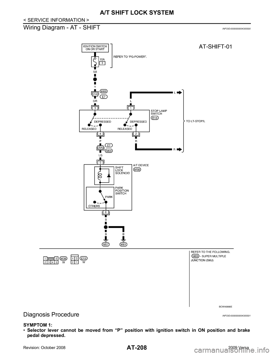
A/T SHIFT LOCK SYSTEM
Description INFOID:0000000004305498
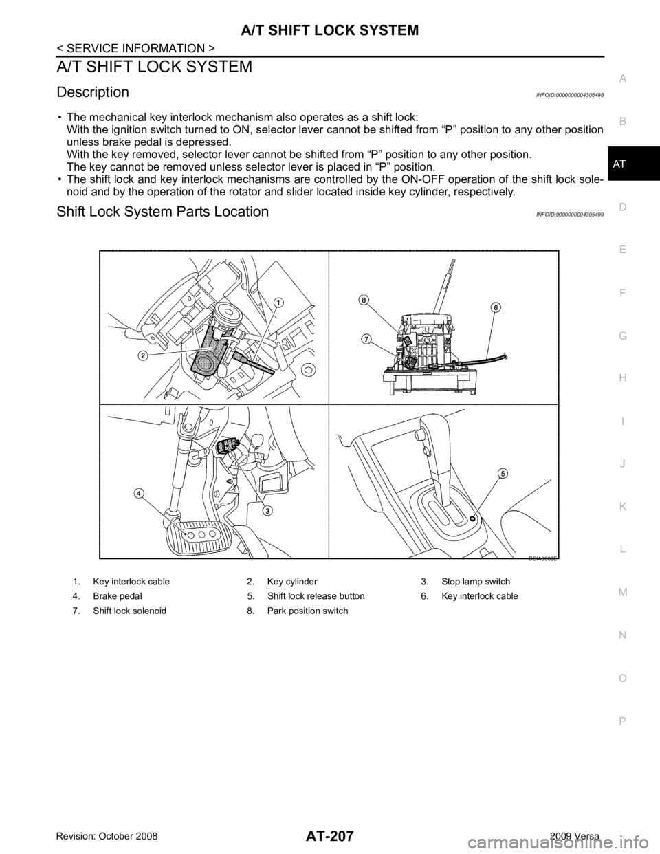
• The mechanical key interlock mechanism also operates as a shift lock: With the ignition switch turned to ON, selector lever cannot be shifted from “P” position to any other position
unless brake pedal is depressed.
With the key removed, selector lever cannot be shifted from “P” position to any other position.
The key cannot be removed unless selector lever is placed in “P” position.
• The shift lock and key interlock mechanisms are controlled by the ON-OFF operation of the shift lock sole-
noid and by the operation of the rotator and sli der located inside key cylinder, respectively.
Shift Lock System Parts Location INFOID:0000000004305499
1. Key interlock cable 2. Key cylinder 3. Stop lamp switch
4. Brake pedal 5. Shift lock release button 6. Key interlock cable
7. Shift lock solenoid 8. Park position switch
Page 213 of 4331
Page 214 of 4331
AT
N
O P
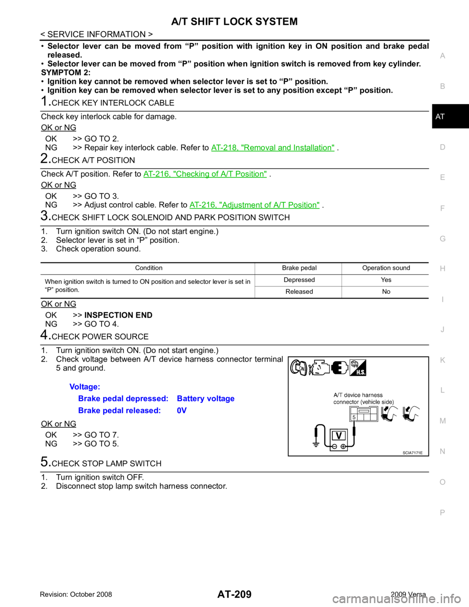
•
Selector lever can be moved fr om “P” position with ignition key in ON position and brake pedal
released.
• Selector lever can be moved from “P” position when ignition switch is removed from key cylinder.
SYMPTOM 2:
• Ignition key cannot be removed when sel ector lever is set to “P” position.
• Ignition key can be removed wh en selector lever is set to any position except “P” position.OK >> GO TO 2.
NG >> Repair key interlock cable. Refer to AT-218, " Removal and Installation " .
Checking of A/T Position " .
OK or NG OK >> GO TO 3.
NG >> Adjust control cable. Refer to AT-216, " Adjustment of A/T Position " .
OK >>
INSPECTION END
NG >> GO TO 4. OK >> GO TO 7.
NG >> GO TO 5.
Page 215 of 4331
.
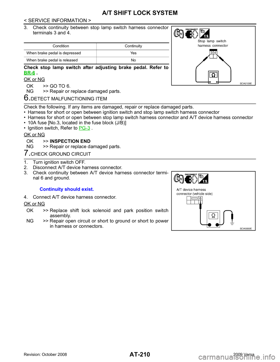
OK or NG OK >> GO TO 6.
NG >> Repair or replace damaged parts. .
OK or NG OK >>
INSPECTION END
NG >> Repair or replace damaged parts. OK >> Replace shift lock solenoid and park position switch
assembly.
NG >> Repair open circuit or short to ground or short to power in harness or connectors.Condition Continuity
When brake pedal is depressed Yes
When brake pedal is released No
Page 216 of 4331
AT
N
O P
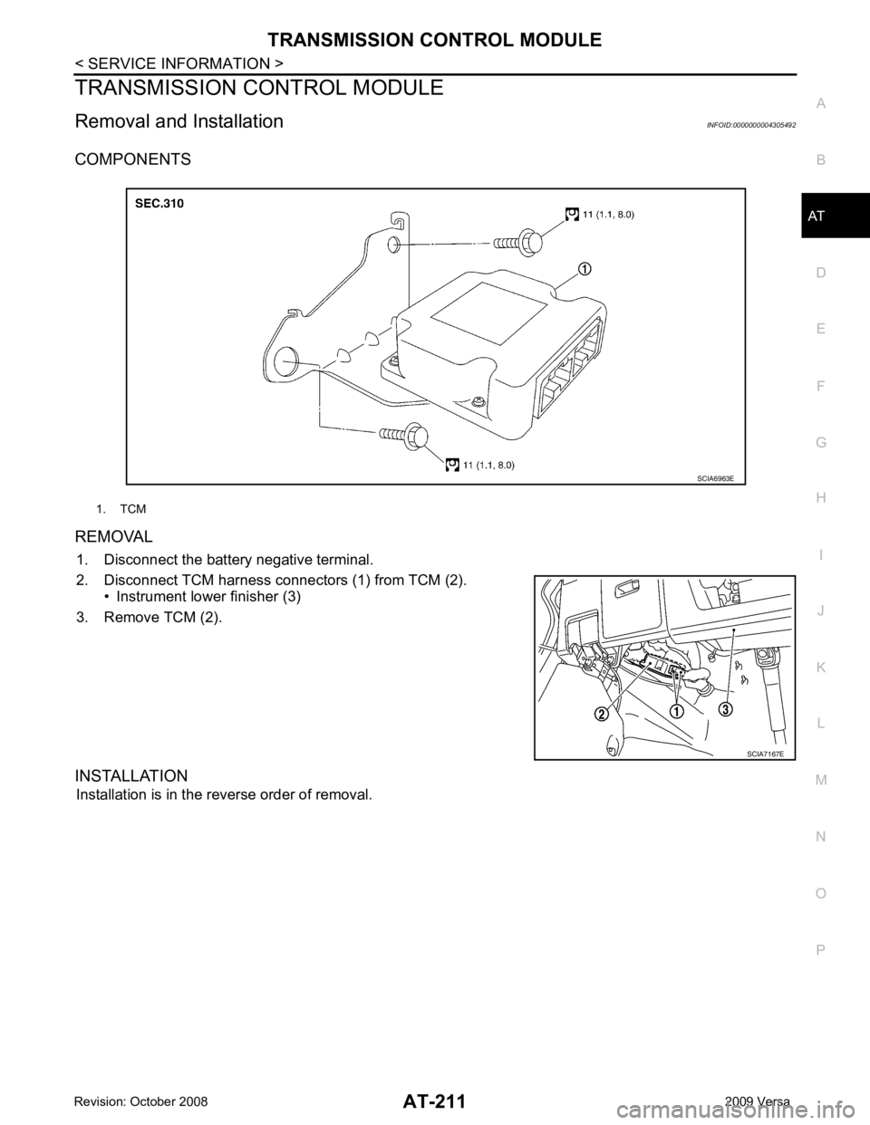
TRANSMISSION CONTROL MODULE
Removal and Installation INFOID:0000000004305492
COMPONENTS
REMOVAL 1. Disconnect the battery negative terminal.
2. Disconnect TCM harness connectors (1) from TCM (2). • Instrument lower finisher (3)
3. Remove TCM (2).
INSTALLATION Installation is in the reverse order of removal. 1. TCM
Page 217 of 4331
Page 218 of 4331
AT
N
O P
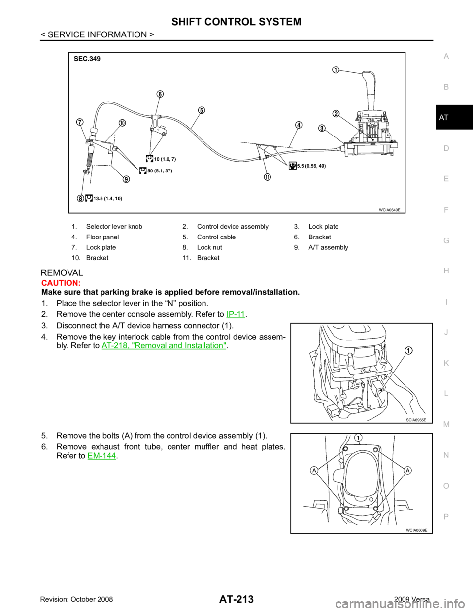
REMOVAL
CAUTION:
Make sure that parking brake is a pplied before removal/installation.
1. Place the selector lever in the “N” position.
2. Remove the center console assembly. Refer to IP-11 .
3. Disconnect the A/T device harness connector (1).
4. Remove the key interlock cabl e from the control device assem-
bly. Refer to AT-218, " Removal and Installation " .
5. Remove the bolts (A) from the control device assembly (1).
6. Remove exhaust front tube, c enter muffler and heat plates.
Refer to EM-144 .
1. Selector lever knob 2. Control device assembly 3. Lock plate
4. Floor panel 5. Control cable 6. Bracket
7. Lock plate 8. Lock nut 9. A/T assembly
10. Bracket 11. Bracket
Page 219 of 4331
Page 220 of 4331
AT
N
O P
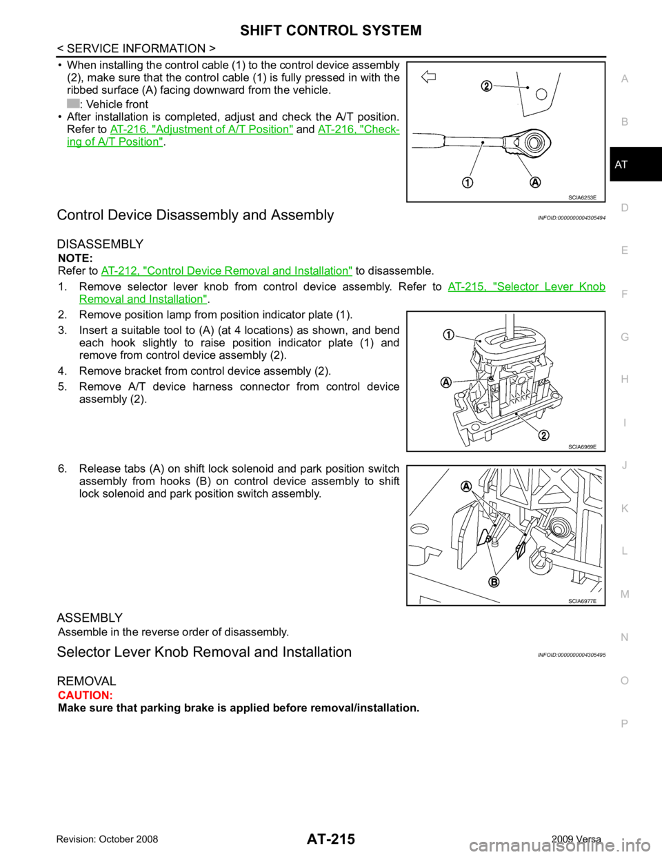
• When installing the control cable (1) to the control device assembly
(2), make sure that the control cable (1) is fully pressed in with the
ribbed surface (A) facing downward from the vehicle.
: Vehicle front
• After installation is completed, adjust and check the A/T position.
Refer to AT-216, " Adjustment of A/T Position " and
AT-216, " Check-
ing of A/T Position " .
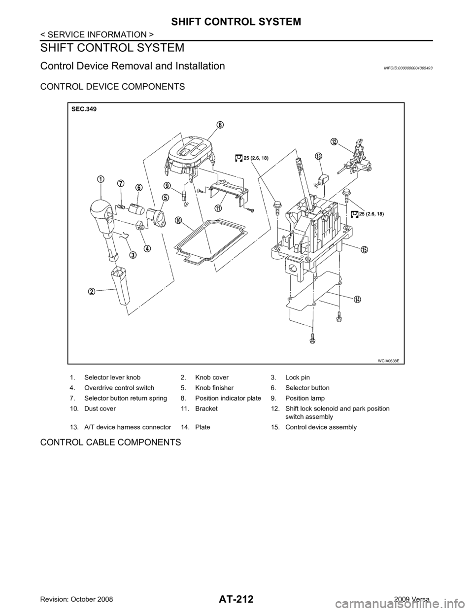
Control Device Disassembly and Assembly INFOID:0000000004305494
DISASSEMBLY NOTE:
Refer to AT-212, " Control Device Removal and Installation " to disassemble.
1. Remove selector lever knob from control device assembly. Refer to AT-215, " Selector Lever Knob
Removal and Installation " .
2. Remove position lamp from position indicator plate (1).
3. Insert a suitable tool to (A) (at 4 locations) as shown, and bend each hook slightly to raise position indicator plate (1) and
remove from control device assembly (2).
4. Remove bracket from control device assembly (2).
5. Remove A/T device harness connector from control device assembly (2).
6. Release tabs (A) on shift lock solenoid and park position switch assembly from hooks (B) on control device assembly to shift
lock solenoid and park position switch assembly.
ASSEMBLY Assemble in the reverse order of disassembly.
Selector Lever Knob Re moval and Installation INFOID:0000000004305495
REMOVAL CAUTION:
Make sure that parking brake is a pplied before removal/installation.
Trending: air condition, fuel tank removal, automatic transmission, oil dipstick, fuse, maintenance, window
