NISSAN LATIO 2009 Service Repair Manual
LATIO 2009
NISSAN
NISSAN
https://www.carmanualsonline.info/img/5/57359/w960_57359-0.png
NISSAN LATIO 2009 Service Repair Manual
Trending: engine coolant, jump start terminals, glove box, inflation pressure, fuel filter, suspension, steering
Page 231 of 4331
![NISSAN LATIO 2009 Service Repair Manual " Control Device Removal and Installation " .
4. Loosen PNP switch bolts. :Bolt
5. Insert the pin (3) [4 mm (0.16 in) dia.] straight into manual shaft (1) adjustment hole.
6. Rotate PNP switch (2) NISSAN LATIO 2009 Service Repair Manual " Control Device Removal and Installation " .
4. Loosen PNP switch bolts. :Bolt
5. Insert the pin (3) [4 mm (0.16 in) dia.] straight into manual shaft (1) adjustment hole.
6. Rotate PNP switch (2)](/img/5/57359/w960_57359-230.png)
" Control Device Removal and Installation " .
4. Loosen PNP switch bolts. :Bolt
5. Insert the pin (3) [4 mm (0.16 in) dia.] straight into manual shaft (1) adjustment hole.
6. Rotate PNP switch (2) until the pin (3) can also be inserted straight into hole in PNP switch (2).
7. Tighten PNP switch bolts to the specified torque. Refer to "COMPONENTS".
8. Remove the pin (3) from adjustment hole after adjusting PNP switch (2).
9. Install the control cable. Refer to AT-212, " Control Device Removal and Installation " .
10. Adjust and check A/T position. Refer to AT-216, " Adjustment of A/T Position " and
AT-216, " Checking of A/
T Position " .
11. Check continuity of PNP switch (2). Refer to AT-176, " Component Inspection " .
12. Install the air duct (inlet). Refer to EM-139 .
Revolution Sensor INFOID:0000000004305505
COMPONENTS
REMOVAL AND INSTALLATION
Removal
1. Disconnect the battery negative terminal.
2. Remove air duct (inlet), air duct and air cleaner case. Refer to EM-139, " Component " .
Page 232 of 4331
AT
N
O P
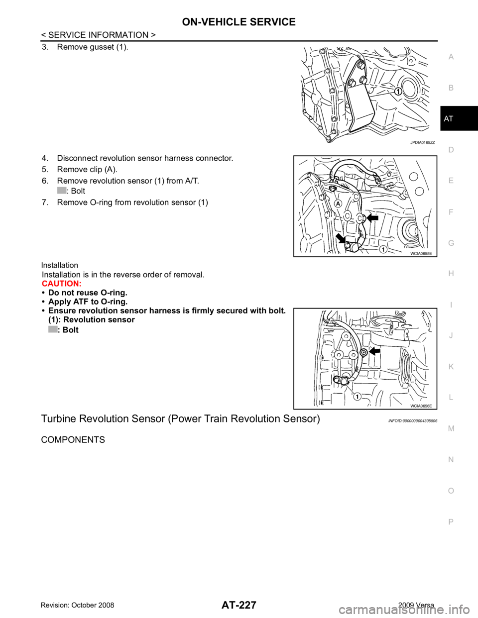
3. Remove gusset (1).
4. Disconnect revolution sensor harness connector.
5. Remove clip (A).
6. Remove revolution sensor (1) from A/T. : Bolt
7. Remove O-ring from revolution sensor (1)
Installation Installation is in the reverse order of removal.
CAUTION:
• Do not reuse O-ring.
• Apply ATF to O-ring.
• Ensure revolution sensor harn ess is firmly secured with bolt.
(1): Revolution sensor
: Bolt
Turbine Revolution Sensor (Power Train Revolution Sensor) INFOID:0000000004305506
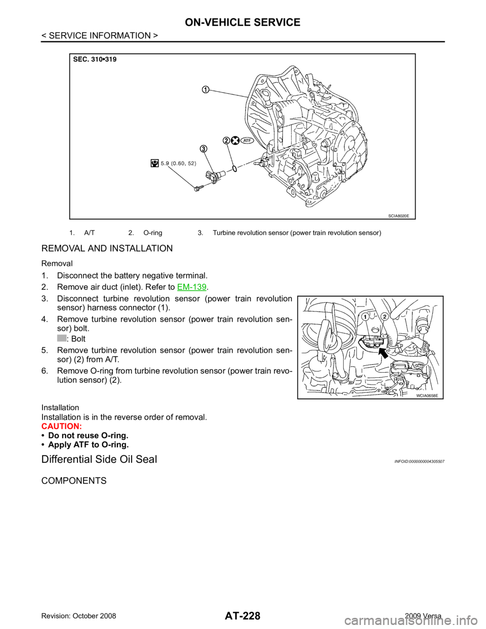
COMPONENTS
Page 233 of 4331
.
3. Disconnect turbine revolution sensor (power train revolution sensor) harness connector (1).
4. Remove turbine revolution sensor (power train revolution sen- sor) bolt.
: Bolt
5. Remove turbine revolution sensor (power train revolution sen- sor) (2) from A/T.
6. Remove O-ring from turbine revolution sensor (power train revo- lution sensor) (2).
Installation
Installation is in the reverse order of removal.
CAUTION:
• Do not reuse O-ring.
• Apply ATF to O-ring.
Differential Side Oil Seal INFOID:0000000004305507
COMPONENTS 1. A/T 2. O-ring 3. Turbine revolution sensor (power train revolution sensor)
Page 234 of 4331
AT
N
O P
REMOVAL AND INSTALLATION
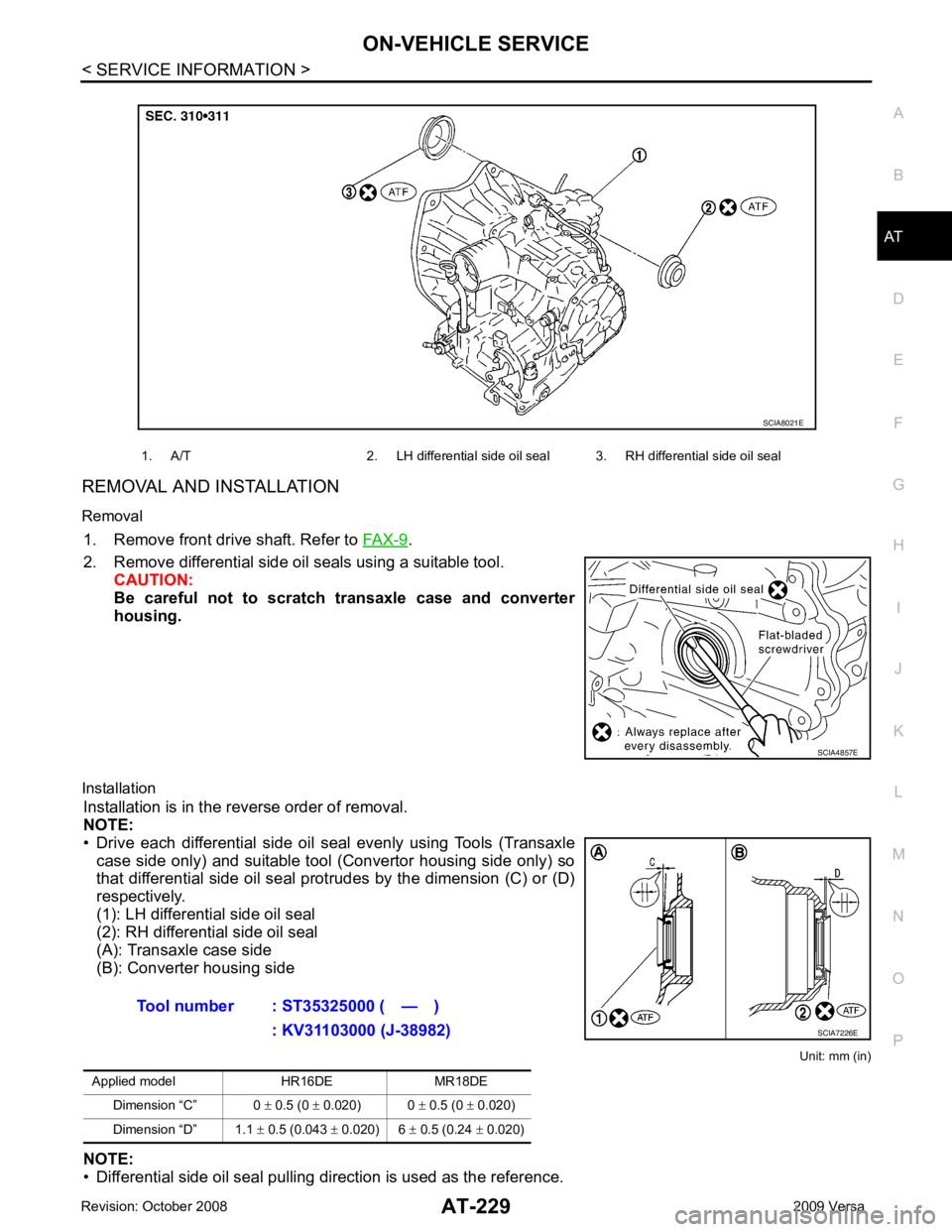
Removal 1. Remove front drive shaft. Refer to FAX-9 .
2. Remove differential side oil seals using a suitable tool. CAUTION:
Be careful not to scratch transaxle case and converter
housing.
Installation Installation is in the reverse order of removal.
NOTE:
• Drive each differential side oil seal evenly using Tools (Transaxle case side only) and suitable tool (Convertor housing side only) so
that differential side oil seal protrudes by the dimension (C) or (D)
respectively.
(1): LH differential side oil seal
(2): RH differential side oil seal
(A): Transaxle case side
(B): Converter housing side
Unit: mm (in)
NOTE:
• Differential side oil seal pulling direction is used as the reference. 1. A/T 2. LH differential side oil seal 3. RH differential side oil seal
Page 235 of 4331
Page 236 of 4331
AT
N
O P
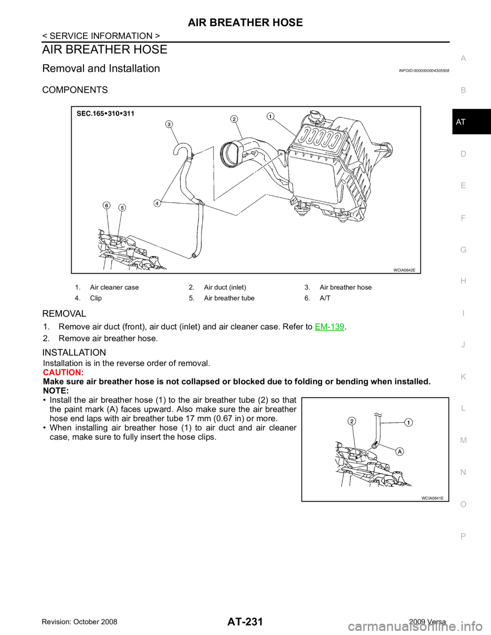
AIR BREATHER HOSE
Removal and Installation INFOID:0000000004305508
COMPONENTS
REMOVAL 1. Remove air duct (front), air duct (inlet) and air cleaner case. Refer to EM-139 .
2. Remove air breather hose.
INSTALLATION Installation is in the reverse order of removal.
CAUTION:
Make sure air breather hose is not collapsed or bl ocked due to folding or bending when installed.
NOTE:
• Install the air breather hose (1) to the air breather tube (2) so that
the paint mark (A) faces upward. Also make sure the air breather
hose end laps with air breather tube 17 mm (0.67 in) or more.
• When installing air breather hose (1) to air duct and air cleaner
case, make sure to fully insert the hose clips. 1. Air cleaner case 2. Air duct (inlet) 3. Air breather hose
4. Clip 5. Air breather tube 6. A/T WCIA0641E
Page 237 of 4331
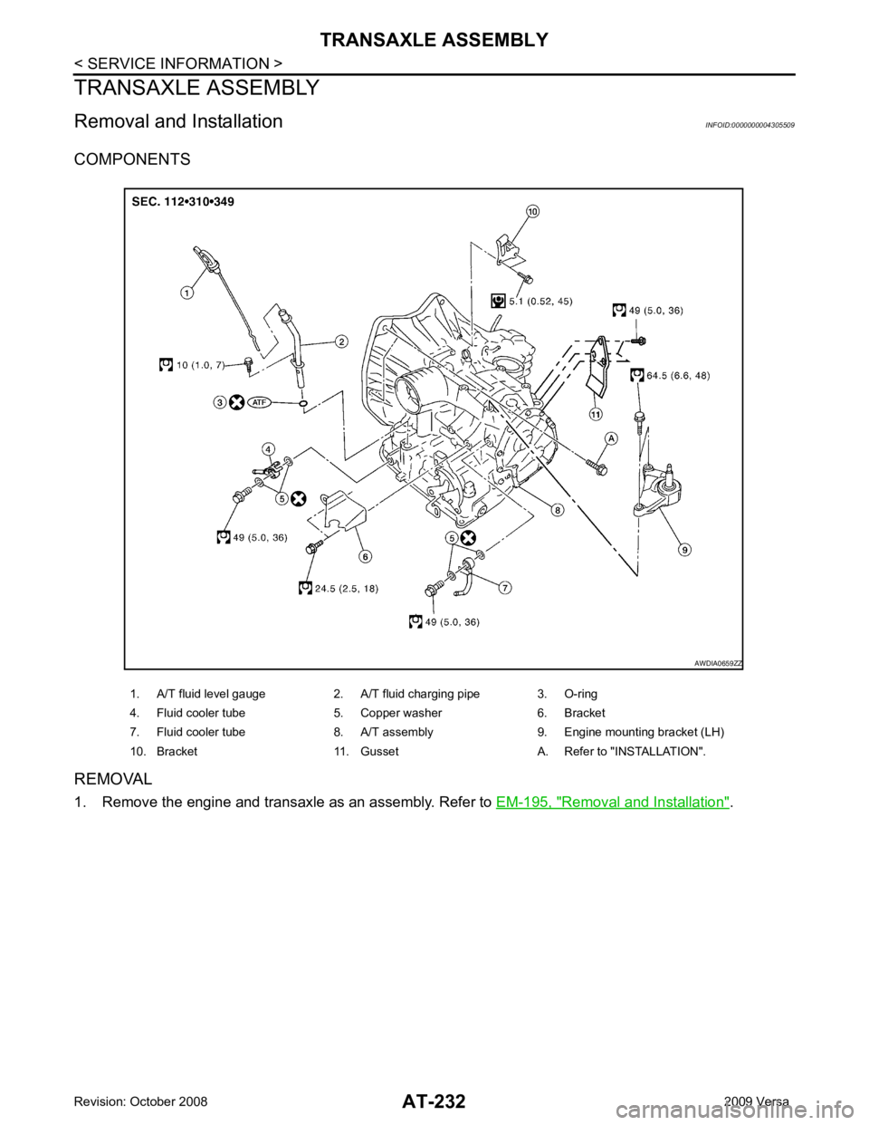
Removal and Installation " .
1. A/T fluid level gauge 2. A/T fluid charging pipe 3. O-ring
4. Fluid cooler tube 5. Copper washer 6. Bracket
7. Fluid cooler tube 8. A/T assembly 9. Engine mounting bracket (LH)
10. Bracket 11. Gusset A. Refer to "INSTALLATION".
Page 238 of 4331
AT
N
O P
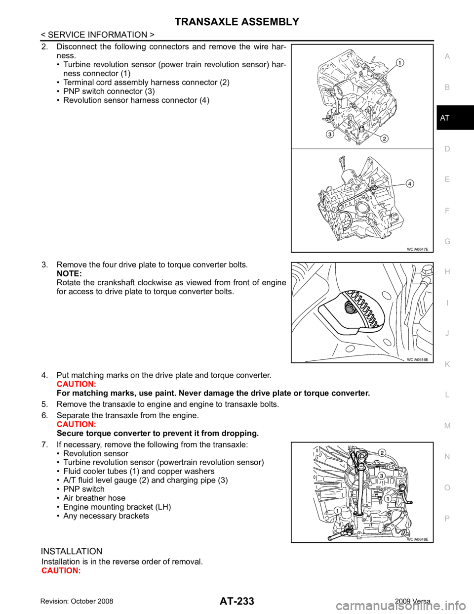
2. Disconnect the following connectors and remove the wire har-
ness.
• Turbine revolution sensor (power train revolution sensor) har-
ness connector (1)
• Terminal cord assembly harness connector (2)
• PNP switch connector (3)
• Revolution sensor harness connector (4)
3. Remove the four drive plate to torque converter bolts. NOTE:
Rotate the crankshaft clockwise as viewed from front of engine
for access to drive plate to torque converter bolts.
4. Put matching marks on the drive plate and torque converter. CAUTION:
For matching marks, use paint. Never dama ge the drive plate or torque converter.
5. Remove the transaxle to engine and engine to transaxle bolts.
6. Separate the transaxle from the engine. CAUTION:
Secure torque converter to prevent it from dropping.
7. If necessary, remove the following from the transaxle: • Revolution sensor
• Turbine revolution sensor (powertrain revolution sensor)
• Fluid cooler tubes (1) and copper washers
• A/T fluid level gauge (2) and charging pipe (3)
• PNP switch
• Air breather hose
• Engine mounting bracket (LH)
• Any necessary brackets
INSTALLATION Installation is in the reverse order of removal.
CAUTION: WCIA0616E
WCIA0648E
Page 239 of 4331
.
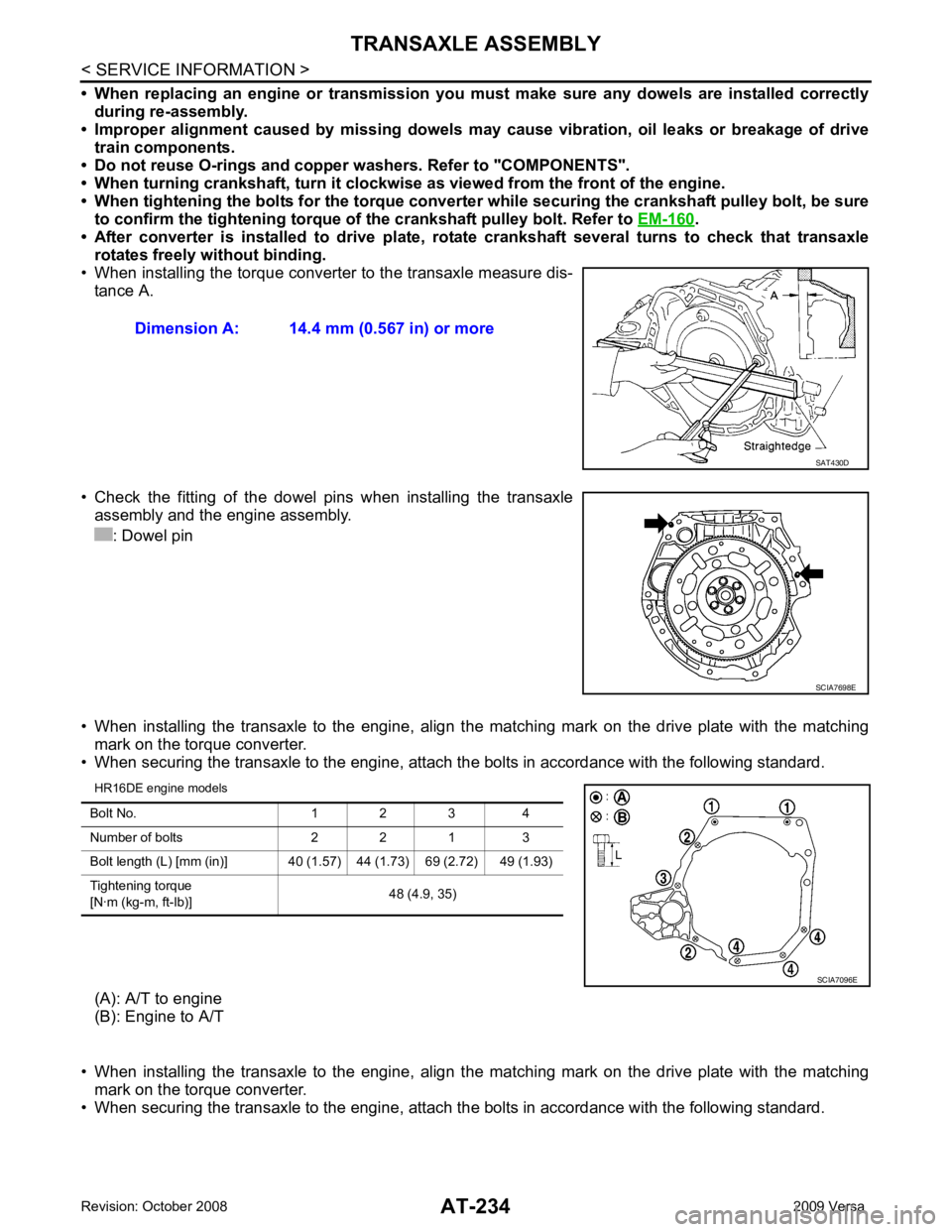
• After converter is installed to drive plate, ro tate crankshaft several turns to check that transaxle
rotates freely without binding.
• When installing the torque converter to the transaxle measure dis- tance A.
• Check the fitting of the dowel pins when installing the transaxle
assembly and the engine assembly.
: Dowel pin
• When installing the transaxle to the engine, align t he matching mark on the drive plate with the matching
mark on the torque converter.
• When securing the transaxle to the engine, attach the bolts in accordance with the following standard.
HR16DE engine models
(A): A/T to engine
(B): Engine to A/T
• When installing the transaxle to the engine, align t he matching mark on the drive plate with the matching
mark on the torque converter.
• When securing the transaxle to the engine, attach the bolts in accordance with the following standard.
Dimension A: 14.4 mm (0.567 in) or more
SCIA7698E
Page 240 of 4331
AT
N
O P
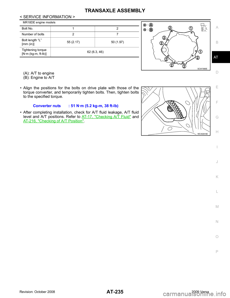
MR18DE engine models
(A): A/T to engine
(B): Engine to A/T
• Align the positions for the bolts on drive plate with those of the torque converter, and temporarily tighten bolts. Then, tighten bolts
to the specified torque.
• After completing installation, chec k for A/T fluid leakage, A/T fluid
level and A/T positions. Refer to AT-17, " Checking A/T Fluid " and
AT-216, " Checking of A/T Position " .
Bolt No. 1 2
Number of bolts 2 7
Bolt length “L”
[mm (in)] 55 (2.17) 50 (1.97)
Tightening torque
[N·m (kg-m, ft-lb)] 62 (6.3, 46)
Trending: relay, oil level, dimensions, remote control, oil dipstick, engine overheat, hood release
![NISSAN LATIO 2009 Service Repair Manual " Control Device Removal and Installation " .
4. Loosen PNP switch bolts. :Bolt
5. Insert the pin (3) [4 mm (0.16 in) dia.] straight into manual shaft (1) adjustment hole.
6. Rotate PNP switch (2) NISSAN LATIO 2009 Service Repair Manual " Control Device Removal and Installation " .
4. Loosen PNP switch bolts. :Bolt
5. Insert the pin (3) [4 mm (0.16 in) dia.] straight into manual shaft (1) adjustment hole.
6. Rotate PNP switch (2)](/img/5/57359/w960_57359-230.png)
