transmission NISSAN LATIO 2009 Service Repair Manual
[x] Cancel search | Manufacturer: NISSAN, Model Year: 2009, Model line: LATIO, Model: NISSAN LATIO 2009Pages: 4331, PDF Size: 58.04 MB
Page 3756 of 4331
MA
N
O P
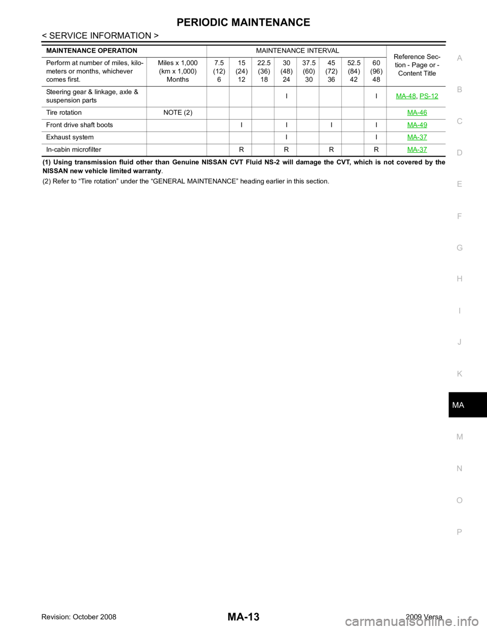
(1) Using transmission fluid other than Genuine NISSAN CVT Flui
d NS-2 will damage the CVT, which is not covered by the
NISSAN new vehicle limited warranty .
(2) Refer to “Tire rotation” under the “GENERAL MAINTENANCE” heading earlier in this section.
Steering gear & linkage, axle &
suspension parts I I
MA-48 ,
PS-12 Tire rotation NOTE (2)
MA-46Front drive shaft boots I I I I
MA-49Exhaust system I I
MA-37In-cabin microfilter R R R R
MA-37
Page 3782 of 4331
CHASSIS AND BODY MAINTENANCE
MA-39
< SERVICE INFORMATION >
C
D E
F
G H
I
J
K
M A
B MA
N
O P
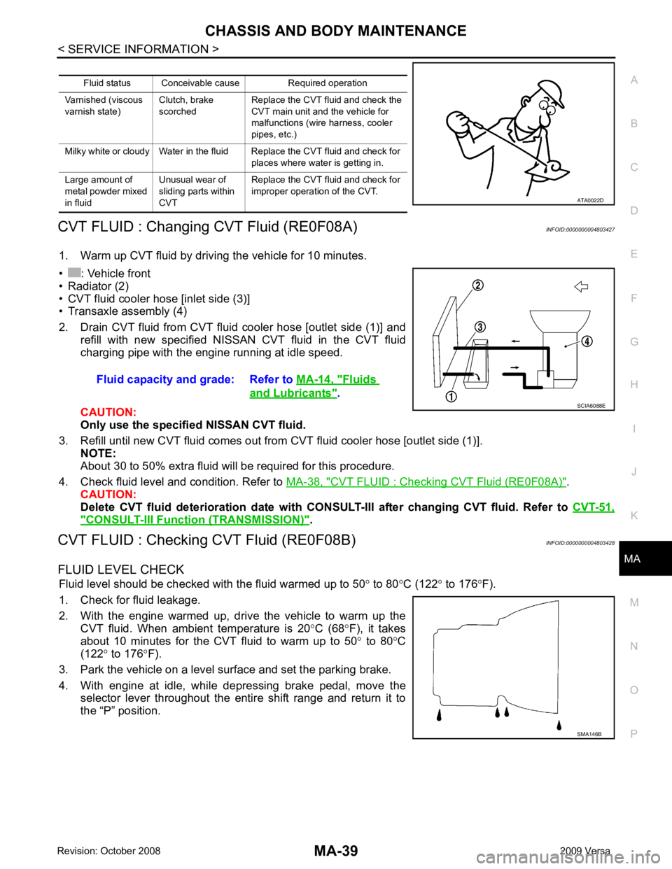
CVT FLUID : Changing CVT Fluid (RE0F08A)
INFOID:0000000004803427
1. Warm up CVT fluid by driving the vehicle for 10 minutes.
• : Vehicle front
• Radiator (2)
• CVT fluid cooler hose [inlet side (3)]
• Transaxle assembly (4)
2. Drain CVT fluid from CVT fluid cooler hose [outlet side (1)] and refill with new specified NISSAN CVT fluid in the CVT fluid
charging pipe with the engine running at idle speed.
CAUTION:
Only use the specifi ed NISSAN CVT fluid.
3. Refill until new CVT fluid comes out from CVT fluid cooler hose [outlet side (1)]. NOTE:
About 30 to 50% extra fluid will be required for this procedure.
4. Check fluid level and condition. Refer to MA-38, " CVT FLUID : Checking CVT Fluid (RE0F08A) " .
CAUTION:
Delete CVT fluid deterioration date with CONSULT-III after changing CVT fluid. Refer to CVT-51," CONSULT-III Function (TRANSMISSION) " .
CVT FLUID : Checking CVT Fluid (RE0F08B) INFOID:0000000004803428
FLUID LEVEL CHECK Fluid level should be checked with the fluid warmed up to 50 ° to 80 °C (122 ° to 176 °F).
1. Check for fluid leakage.
2. With the engine warmed up, drive the vehicle to warm up the CVT fluid. When ambient temperature is 20 °C (68 °F), it takes
about 10 minutes for the CVT fluid to warm up to 50 ° to 80 °C
(122 ° to 176 °F).
3. Park the vehicle on a level surface and set the parking brake.
4. With engine at idle, while depressing brake pedal, move the selector lever throughout the entire shift range and return it to
the “P” position. Fluid status Conceivable cause Required operation
Varnished (viscous
varnish state) Clutch, brake
scorched Replace the CVT fluid and check the
CVT main unit and the vehicle for
malfunctions (wire harness, cooler
pipes, etc.)
Milky white or cloudy Water in the fluid Replace the CVT fluid and check for places where water is getting in.
Large amount of
metal powder mixed
in fluid Unusual wear of
sliding parts within
CVT Replace the CVT fluid and check for
improper operation of the CVT. ATA0022D
Fluid capacity and grade: Refer to
MA-14, " Fluids
and Lubricants " .
SCIA6088E
SMA146B
Page 3784 of 4331
![NISSAN LATIO 2009 Service Repair Manual CHASSIS AND BODY MAINTENANCE
MA-41
< SERVICE INFORMATION >
C
D E
F
G H
I
J
K
M A
B MA
N
O P
• : Vehicle front
• Radiator (2)
• CVT fluid cooler hose [inlet side (3)]
• Transaxle assembly (4)
2](/img/5/57359/w960_57359-3783.png "NISSAN LATIO 2009 Service Repair Manual CHASSIS AND BODY MAINTENANCE
MA-41
< SERVICE INFORMATION >
C
D E
F
G H
I
J
K
M A
B MA
N
O P
• : Vehicle front
• Radiator (2)
• CVT fluid cooler hose [inlet side (3)]
• Transaxle assembly (4)
2")
CHASSIS AND BODY MAINTENANCE
MA-41
< SERVICE INFORMATION >
C
D E
F
G H
I
J
K
M A
B MA
N
O P
• : Vehicle front
• Radiator (2)
• CVT fluid cooler hose [inlet side (3)]
• Transaxle assembly (4)
2. Drain CVT fluid from CVT fluid cooler hose [outlet side (1)] and refill with new specified NISSAN CVT fluid in the CVT fluid
charging pipe with the engine running at idle speed.
CAUTION:
Only use the specifi ed NISSAN CVT fluid.
3. Refill until new CVT fluid comes out from CVT fluid cooler hose [outlet side (1)]. NOTE:
About 30 to 50% extra fluid will be required for this procedure.
4. Check fluid level and condition. Refer to MA-39, " CVT FLUID : Checking CVT Fluid (RE0F08B) " .
CAUTION:
Delete CVT fluid deterioration date with CO NSULT-III after changing CVT fluid. Refer to CVT-230," CONSULT-III Function (TRANSMISSION) " .
CLUTCH FLUID
CLUTCH FLUID : Air Bleeding Procedure INFOID:0000000004683730
CAUTION:
Do not spill clutch fluid onto painted surfaces. If it spills, wipe up immediately and wash the affected
area with water.
NOTE:
• Do not use a vacuum assist or any other type of pow er bleeder on this system. Use of a vacuum assist or
power bleeder will not purge all the air from the system.
• Carefully monitor fluid level in reservoir tank during bleeding operation.
1. Fill master cylinder reservoir tank with new clutch fluid.
2. Connect a transparent vinyl tube and container to the bleeding connector (1) on the CSC.
3. Depress and release the clutch pedal slowly and fully 15 times at an interval of two to three seconds and release the clutch
pedal.
4. Push in the lock pin (1) of the bleeding connector (2), and maintain the position. • RS5F91R transaxle models
CAUTION:
Hold the lock pin in to preven t the bleeding connector from
separating when fluid pressure is applied.
Fluid capacity and grade: Refer to
MA-14, " Fluids
and Lubricants " .
SCIA6088E
PCIB1494E
PCIB1495E
Page 4245 of 4331
STC
N
O P
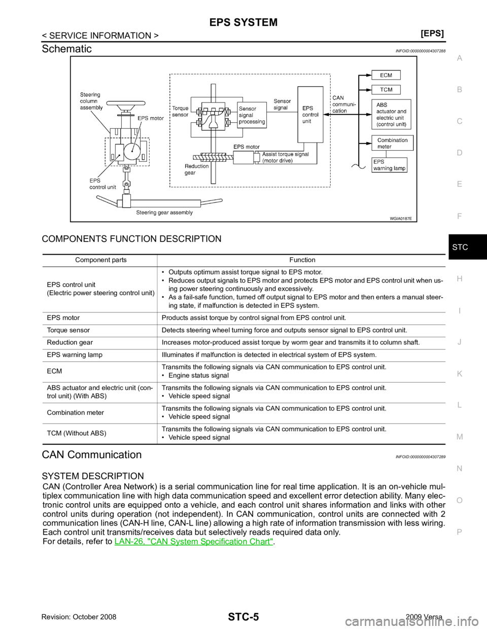
Schematic
INFOID:0000000004307288
COMPONENTS FUNCTION DESCRIPTION
CAN Communication INFOID:0000000004307289
SYSTEM DESCRIPTION CAN (Controller Area Network) is a serial communication li ne for real time application. It is an on-vehicle mul-
tiplex communication line with high data communication speed and excellent error detection ability. Many elec-
tronic control units are equipped onto a vehicle, and each control unit shares information and links with other
control units during operation (not independent). In CAN communication, control units are connected with 2
communication lines (CAN-H line, CAN-L line) allowing a high rate of information transmission with less wiring.
Each control unit transmits/receives data but selectively reads required data only.
For details, refer to LAN-26, " CAN System Specification Chart " .
Page 4258 of 4331
![NISSAN LATIO 2009 Service Repair Manual “ CONTROL UNIT [C1608] ” displayed?
YES >> Replace EPS control unit. Refer to
PS-9, " Removal and Installation " .
NO >> INSPECTION END
DTC C1609 CAN VHCL SPEED INFOID:0000000004307303
CONSULT-I](/img/5/57359/w960_57359-4257.png "NISSAN LATIO 2009 Service Repair Manual “ CONTROL UNIT [C1608] ” displayed?
YES >> Replace EPS control unit. Refer to
PS-9, \" Removal and Installation \" .
NO >> INSPECTION END
DTC C1609 CAN VHCL SPEED INFOID:0000000004307303
CONSULT-I")
“ CONTROL UNIT [C1608] ” displayed?
YES >> Replace EPS control unit. Refer to
PS-9, " Removal and Installation " .
NO >> INSPECTION END
DTC C1609 CAN VHCL SPEED INFOID:0000000004307303
CONSULT-III REFERENCE VALUE IN DATA MONITOR MODE
Data are reference value.
* : It is not a malfunction, though it might not be corresponding just after ignition switch is turned ON.
DIAGNOSTIC PROCEDURE CONSULT-III Function (METER/M&A) " .
Is any malfunction detec ted by self-diagnosis?YES >> Check the malfunctioning system.
NO-1 >> With ABS: GO TO 2.
NO-2 >> Without ABS: GO TO 3. CONSULT-III
Function (ABS) " .
Is any malfunction detec ted by self-diagnosis?YES >> Check the malfunctioning system.
NO >> GO TO 4. CONSULT-III Function (TRANSMISSION) " .
Is any malfunction detec ted by self-diagnosis?YES >> Check the malfunctioning system.
NO >> GO TO 4. EPS Control Unit Input/Output Signal Reference
Value " .
OK or NG OK >> GO TO 5.
NG >> Check EPS control unit pin terminals for dam age or loose connection with harness connector. If
any items are damaged, repair or replace damaged parts.
Page 4263 of 4331
![NISSAN LATIO 2009 Service Repair Manual STC
N
O P
Is the “ CAN COMM CIRCUIT [U1000] ” displayed?
YES >> Perform trouble diagnosis for CAN communication line. Refer to
STC-19, " DTC U1000 CAN
COMM CIRCUIT " .
NO-1 >> With](/img/5/57359/w960_57359-4262.png "NISSAN LATIO 2009 Service Repair Manual STC
N
O P
Is the “ CAN COMM CIRCUIT [U1000] ” displayed?
YES >> Perform trouble diagnosis for CAN communication line. Refer to
STC-19, \" DTC U1000 CAN
COMM CIRCUIT \" .
NO-1 >> With")
STC
N
O P
Is the “ CAN COMM CIRCUIT [U1000] ” displayed?
YES >> Perform trouble diagnosis for CAN communication line. Refer to
STC-19, " DTC U1000 CAN
COMM CIRCUIT " .
NO-1 >> With ABS: GO TO 2.
NO-2 >> Without ABS: GO TO 3. CONSULT-III
Function (ABS) " .
Is any malfunction detected by self-diagnosis? YES >> Check the malfunctioning system.
NO >> GO TO 4. CONSULT-III Function (TRANSMISSION) " .
Is any malfunction detected by self-diagnosis? YES >> Check the malfunctioning system.
NO >> GO TO 4. CONSULT-III Function (METER/M&A) " .
Is any malfunction detected by self-diagnosis? YES >> Check the malfunctioning system.
NO >> GO TO 5. CONSULT-III Function (ENGINE) " (MR TYPE 1),
EC-1116," CONSULT-III Function (ENGINE) " (MR TYPE 2) or
EC-103, " CONSULT-III Function " (HR16DE).
Is any malfunction detected by self-diagnosis? YES >> Check the malfunctioning system.
NO >> GO TO 6. DTC C1606 EPS MOTOR " .
OK or NG OK >> GO TO 7.
NG >> Repair or replace damaged parts. EPS Control Unit Input/Output Signal Reference
Value " .
OK or NG OK >> GO TO 8.
NG >> Check EPS control unit pin terminals for damage or loose connection with harness connector. If
any items are damaged, repair or replace damaged parts. OK >>
INSPECTION END
NG >> Check the steering wheel turning force because there may be mechanical malfunction. Refer to PS-6, " On-Vehicle Inspection and Service " .
Unbalance Steering Wheel Turning Forc e and Return Between Right and Left
INFOID:0000000004307310
SYMPTOM: