transmission NISSAN LATIO 2009 Service Repair Manual
[x] Cancel search | Manufacturer: NISSAN, Model Year: 2009, Model line: LATIO, Model: NISSAN LATIO 2009Pages: 4331, PDF Size: 58.04 MB
Page 1301 of 4331
CVT
N
O P
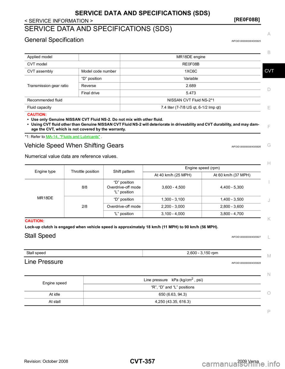
SERVICE DATA AND SPECIFICATIONS (SDS)
General Specification INFOID:0000000004305825
*1: Refer to MA-14, " Fluids and Lubricants " .
Vehicle Speed When Shifting Gears INFOID:0000000004305826
Numerical value data are reference values.
CAUTION:
Lock-up clutch is engaged when vehi cle speed is approximately 18 km/h (11 MPH) to 90 km/h (56 MPH).
Stall Speed INFOID:0000000004305827
Line Pressure INFOID:0000000004305828
Applied model
MR18DE engine
CVT model RE0F08B
CVT assembly Model code number 1XC6C
Transmission gear ratio “D” position Variable
Reverse 2.689
Final drive 5.473
Recommended fluid NISSAN CVT Fluid NS-2*1
Fluid capacity 7.4 liter (7-7/8 US qt, 6-1/2 Imp qt)
CAUTION:
• Use only Genuine NISSAN CVT Fluid NS-2. Do not mix with other fluid.
• Using CVT fluid other than Genuine NISSAN CVT Fluid NS-2 will deteriorate in driveability and CVT durability, and may dam- age the CVT, which is not covered by the warranty. Stall speed
2,600 - 3,150 rpmEngine speed
Line pressure kPa (kg/cm
2
, psi)
“R”, “D” and “L” positions
At idle 650 (6.63, 94.3)
At stall 4,250 (43.35, 616.3)
Page 1312 of 4331
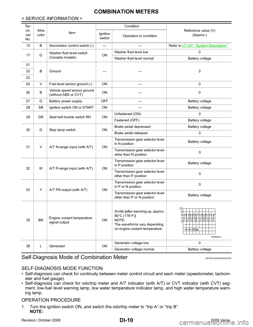
System Description " .
17 G Washer fluid level switch
(Canada models) ONWasher fluid level low 0
Washer fluid level normal Battery voltage
21 B Ground — — 0
22
23
24 V Fuel level sensor ground (-) ON — 0
26 B Vehicle speed sensor ground
(without ABS or CVT) ON — 0
27 G Battery power supply OFF — Battery voltage
28 SB Ignition switch ON or START ON — Battery voltage
29 GR Seat belt buckle switch RH ON Unfastened (ON) 0
Fastened (OFF) Battery voltage
30 G Stop lamp switch ON Brake pedal depressed Battery voltage
Brake pedal released 0
31 V A/T N-range input (with A/T) ON Transmission gear selector lever
in N position Battery voltage
Transmission gear selector lever
other than N position 0
32 W A/T P-range input (with A/T) ON Transmission gear selector lever
in P position Battery voltage
Transmission gear selector lever
other than P position 0
33 Y A/T PN output (with A/T) ON Transmission gear selector lever
in P or N position 0
Transmission gear selector lever
other than P or N position Battery voltage
35 BR Engine coolant temperature
signal output ONAt idle [after warming up, approx.
80 °C (176 °F)]
NOTE:
The waveforms vary depending
on engine coolant temperature.
38 L Generator ON Generator voltage low 0
Generator voltage normal Battery voltage
Ter-
mi-
nal
No. Wire
color Item Condition
Reference value (V)
(Approx.)
Ignition
switch Operation or condition
Page 1318 of 4331
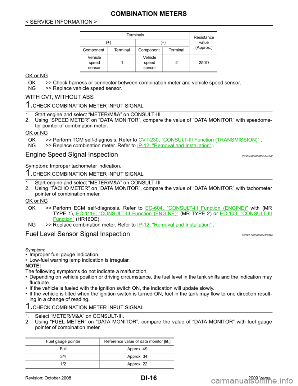
OK >> Check harness or connector between combination meter and vehicle speed sensor.
NG >> Replace vehicle speed sensor.
WITH CVT, WITHOUT ABS OK >> Perform TCM self-diagnosis. Refer to
CVT-230, " CONSULT-III Function (TRANSMISSION) " .
NG >> Replace combination meter. Refer to IP-12, " Removal and Installation " .
Engine Speed Signal Inspection INFOID:0000000004307009
Symptom: Improper tachometer indication. OK >> Perform ECM self-diagnosis. Refer to
EC-604, " CONSULT-III Function (ENGINE) " with (MR
TYPE 1), EC-1116, " CONSULT-III Function (ENGINE) " (MR TYPE 2) or
EC-103, " CONSULT-III
Function " (HR16DE).
NG >> Replace combination meter. Refer to IP-12, " Removal and Installation " .
Fuel Level Sensor Signal Inspection INFOID:0000000004307010
Symptom:
• Improper fuel gauge indication.
• Low-fuel warning lamp indication is irregular.
NOTE:
The following symptoms do not indicate a malfunction.
• Depending on vehicle position or driving circumstance, the fuel level in the tank shifts and the indication may
fluctuate.
• If the vehicle is fueled with the ignition switch ON, the indication will update slowly.
• If the vehicle is tilted when the ignition switch is turned ON, fuel in the tank may flow to one direction result-
ing in a change of reading.
Page 1338 of 4331
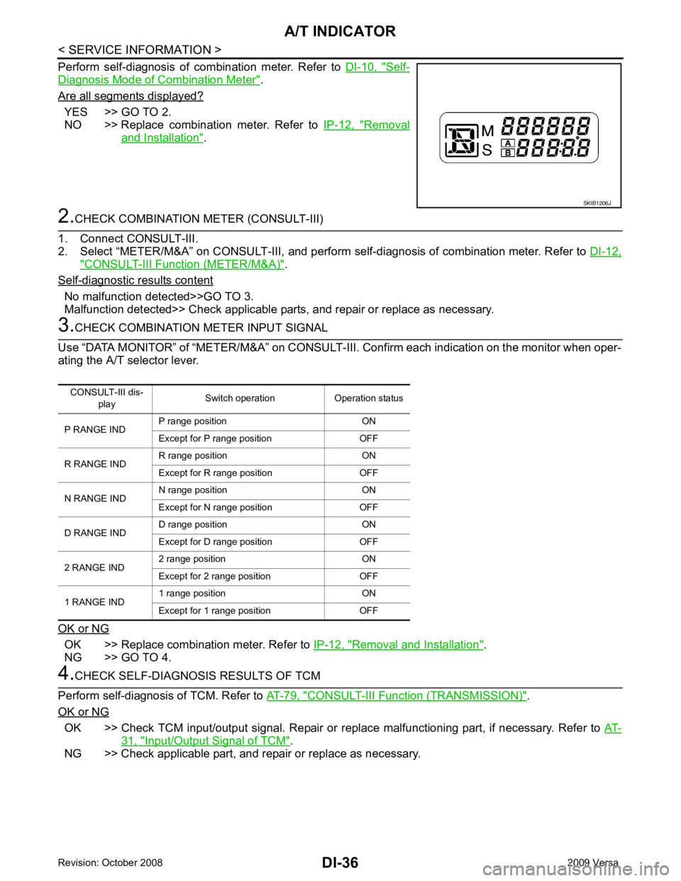
Self-
Diagnosis Mode of Combination Meter " .
Are all segments displayed? YES >> GO TO 2.
NO >> Replace combination meter. Refer to IP-12, " Removal
and Installation " .
" CONSULT-III Function (METER/M&A) " .
Self - diagnostic results content
No malfunction detected>>GO TO 3.
Malfunction detected>> Check applicable parts, and repair or replace as necessary. OK >> Replace combination meter. Refer to
IP-12, " Removal and Installation " .
NG >> GO TO 4. CONSULT-III Functi
on (TRANSMISSION) " .
OK or NG OK >> Check TCM input/output signal. Repair or repl
ace malfunctioning part, if necessary. Refer to AT-31, " Input/Output Signal of TCM " .
NG >> Check applicable part, and repair or replace as necessary.
Page 1343 of 4331
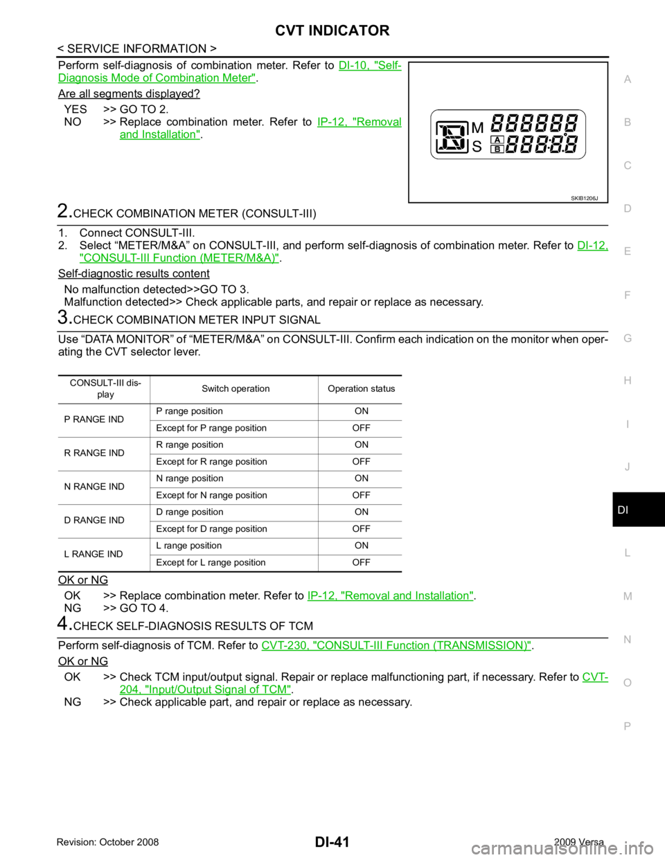
CVT INDICATOR
DI-41
< SERVICE INFORMATION >
C
D E
F
G H
I
J
L
M A
B DI
N
O P
Perform self-diagnosis of combination meter. Refer to
DI-10, " Self-
Diagnosis Mode of Combination Meter " .
Are all segments displayed? YES >> GO TO 2.
NO >> Replace combination meter. Refer to IP-12, " Removal
and Installation " .
2.
CHECK COMBINATION METER (CONSULT-III)
1. Connect CONSULT-III.
2. Select “METER/M&A” on CONSULT-III, and perform se lf-diagnosis of combination meter. Refer to DI-12," CONSULT-III Function (METER/M&A) " .
Self - diagnostic results content
No malfunction detected>>GO TO 3.
Malfunction detected>> Check applicable parts, and repair or replace as necessary. 3.
CHECK COMBINATION METER INPUT SIGNAL
Use “DATA MONITOR” of “METER/M&A” on CONSULT-II I. Confirm each indication on the monitor when oper-
ating the CVT selector lever.
OK or NG OK >> Replace combination meter. Refer to
IP-12, " Removal and Installation " .
NG >> GO TO 4. 4.
CHECK SELF-DIAGNOSIS RESULTS OF TCM
Perform self-diagnosis of TCM. Refer to CVT-230, " CONSULT-III Function (TRANSMISSION) " .
OK or NG OK >> Check TCM input/output signal. Repair or repl
ace malfunctioning part, if necessary. Refer to CVT-204, " Input/Output Signal of TCM " .
NG >> Check applicable part, and repair or replace as necessary. SKIB1206J
CONSULT-III dis-
play Switch operation Operation status
P RANGE IND P range position ON
Except for P range position OFF
R RANGE IND R range position ON
Except for R range position OFF
N RANGE IND N range position ON
Except for N range position OFF
D RANGE IND D range position ON
Except for D range position OFF
L RANGE IND L range position ON
Except for L range position OFF
Page 1421 of 4331
EC
NP
O
CAN COMMUNICATION
System Description INFOID:0000000004780026
CAN (Controller Area Network) is a serial communication li ne for real time application. It is an on-vehicle mul-
tiplex communication line with high data communication speed and excellent error detection ability. Many elec-
tronic control units are equipped onto a vehicle, and each control unit shares information and links with other
control units during operation (not independent). In CAN communication, control units are connected with 2
communication lines (CAN H line, CAN L line) allowing a high rate of information transmission with less wiring.
Each control unit transmits/receives data but selectively reads required data only.
Refer to LAN-26, " CAN Communication Signal Chart " , about CAN communication for detail..
Page 1713 of 4331
EC
NP
O
P0607 ECM
Description INFOID:0000000004780240
CAN (Controller Area Network) is a serial communication li ne for real time application. It is an on-vehicle mul-
tiplex communication line with high data communication speed and excellent error detection ability. Many elec-
tronic control units are equipped onto a vehicle, and each control unit shares information and links with other
control units during operation (not independent). In CAN communication, control units are connected with 2
communication lines (CAN H line, CAN L line) allowing a high rate of information transmission with less wiring.
Each control unit transmits/receives data but selectively reads required data only.
DTC Logic INFOID:0000000004780241
DTC DETECTION LOGIC
DTC CONFIRMATION PROCEDURE YES >> Go to
EC-357, " Diagnosis Procedure " .
NO >> INSPECTION END
Diagnosis Procedure INFOID:0000000004780242Diagnosis Description "
3. Perform DTC CONFIRMATION PROCEDURE. Refer to
EC-357, " DTC Logic " .
4. Check DTC.
Is the DTC P0607 displayed again? YES >> GO TO 2.
NO >> INSPECTION END ADDITIONAL SERVICE WHEN REPLACING CONTROL UNIT : Special Repair Require-
ment " .
>> INSPECTION END
DTC No. Trouble diagnosis name DTC detecting condition Possible cause
P0607 CAN communication bus When detecting error during the initial diagnosis
of CAN controller of ECM. • ECM
Page 1849 of 4331
![NISSAN LATIO 2009 Service Repair Manual PRECAUTIONS
EC-493
< PRECAUTION >
[HR16DE] C
D E
F
G H
I
J
K L
M A EC
NP
O
• Be sure to route and secure the harnesses properly
after work. The interference of the harness with
a bracket, etc. may](/img/5/57359/w960_57359-1848.png "NISSAN LATIO 2009 Service Repair Manual PRECAUTIONS
EC-493
< PRECAUTION >
[HR16DE] C
D E
F
G H
I
J
K L
M A EC
NP
O
• Be sure to route and secure the harnesses properly
after work. The interference of the harness with
a bracket, etc. may")
PRECAUTIONS
EC-493
< PRECAUTION >
[HR16DE] C
D E
F
G H
I
J
K L
M A EC
NP
O
• Be sure to route and secure the harnesses properly
after work. The interference of the harness with
a bracket, etc. may cause the MIL to li ght up due to the short circuit.
• Be sure to connect rubber tubes properly afte r work. A misconnected or disconnected rubber tube
may cause the MIL to light up due to the malfuncti on of the EVAP system or fuel injection system,
etc.
• Be sure to erase the unnecessary malfunction informa tion (repairs completed) from the ECM and
TCM (Transmission control module) before returning the vehicle to the customer.
General Precautions INFOID:0000000004780395
• Always use a 12 volt battery as power source.
• Do not attempt to disconnect battery cables while engine is
running.
• Before connecting or disc onnecting the ECM harness con-
nector, turn ignition switch OFF and disconnect negative bat-
tery cable. Failure to do so may damage the ECM because
battery voltage is applied to ECM even if ignition switch is
turned OFF.
• Before removing parts, turn ig nition switch OFF and then dis-
connect negative battery cable.
• Do not disassemble ECM.
• If a battery cable is disconnect ed, the memory will return to
the ECM value.
The ECM will now start to self-control at its initial value. Thus,
engine operation can vary slight ly in this case. However, this
is not an indication of a malf unction. Do not replace parts
because of a slight variation.
• If the battery is disconnected, the following emission-related
diagnostic information will be cleared within 24 hours.
- Diagnostic trouble codes
- 1st trip diagnostic trouble codes
- Freeze frame data
- 1st trip freeze frame data
- System readiness test (SRT) codes
- Test values
• When connecting ECM harness c onnector (1), fasten (B) it
securely with a lever as far as it will go as shown in the figure.
• When connecting or disconnect ing pin connectors into or
from ECM, take care not to damage pin terminals (bend or
break).
Make sure that there are not any bends or breaks on ECM pin
terminal, when connecting pin connectors.
• Securely connect ECM harness connectors.
A poor connection can cause an extremely high (surge) volt-
age to develop in coil and cond enser, thus resulting in dam-
age to ICs.
• Keep engine control system harness at least 10 cm (4 in) away
from adjacent harness, to prevent engine control system mal- SEF289H
2. ECM
A. Loosen PBIA9222J
PBIB2947E
PBIB0090E
Page 1860 of 4331

Transmission Condition Specification
A/T No load* (in P or N position) 6 ± 5 °BTDC
M/T No load* (in Neutral position) 6 ± 5 °BTDC Condition Specification (U
sing CONSULT-III or GST)
At idle 10 – 35 %
At 2,500 rpm 10 – 35 %Supply voltage
Battery voltage (11 – 14 V)
Output voltage at idle 0.9 – 1.3V*
Mass air flow (Using CONSULT-III or GST) 1.0 – 4.0 g·m/sec at idle*
2.0 – 10.0 g·m/sec at 2,500 rpm*
Page 1869 of 4331
![NISSAN LATIO 2009 Service Repair Manual PRECAUTIONS
EC-513
< SERVICE INFOMATION >
[MR TYPE 1] C
D E
F
G H
I
J
K L
M A EC
NP
O
• Be sure to connect rubber tubes properly afte
r work. A misconnected or disconnected rubber tube](/img/5/57359/w960_57359-1868.png "NISSAN LATIO 2009 Service Repair Manual PRECAUTIONS
EC-513
< SERVICE INFOMATION >
[MR TYPE 1] C
D E
F
G H
I
J
K L
M A EC
NP
O
• Be sure to connect rubber tubes properly afte
r work. A misconnected or disconnected rubber tube")
PRECAUTIONS
EC-513
< SERVICE INFOMATION >
[MR TYPE 1] C
D E
F
G H
I
J
K L
M A EC
NP
O
• Be sure to connect rubber tubes properly afte
r work. A misconnected or disconnected rubber tube
may cause the MIL to light up due to the malfunction of the fuel injection system, etc.
• Be sure to erase the unnecessary malfunction informa tion (repairs completed) from the ECM and
TCM (Transmission control module) before returning the vehicle to the customer.
Precaution INFOID:0000000004537016
• Always use a 12 volt battery as power source.
• Do not attempt to disconnect battery cables while engine is
running.
• Before connecting or disc onnecting the ECM harness con-
nector, turn ignition switch OFF and disconnect negative bat-
tery cable. Failure to do so may damage the ECM because
battery voltage is applied to ECM even if ignition switch is
turned OFF.
• Before removing parts, turn ig nition switch OFF and then dis-
connect negative battery cable.
• Do not disassemble ECM.
• If battery cable is disconnected, the memory will return to the
initial ECM values.
The ECM will now start to self-c ontrol at its initial values.
Engine operation can vary slight ly in this case. However, this
is not an indication of a malf unction. Do not replace parts
because of a slight variation.
• If the battery is disconnected, the following emission-related
diagnostic information will be lost within 24 hours.
- Diagnostic trouble codes
- 1st trip diagnostic trouble codes
- Freeze frame data
- 1st trip freeze frame data
- System readiness test (SRT) codes
- Test values
• When connecting ECM harness connector, fasten (B) it
securely with a lever (1) as far as it will go as shown in the fig-
ure.
- ECM (2)
- Loosen (A)
• When connecting or disconnect ing pin connectors into or
from ECM, take care not to damage pin terminals (bend or
break).
Make sure that there are not any bends or breaks on ECM pin
terminal, when connecting pin connectors.
• Securely connect ECM harness connectors.
A poor connection can cause an extremely high (surge) volt-
age to develop in coil and cond enser, thus resulting in dam-
age to ICs.
• Keep engine control system harness at least 10 cm (4 in) away
from adjacent harness, to prevent engine control system mal-
functions due to receiving externa l noise, degraded operation
of ICs, etc. SEF289H
PBIA9222J
PBIB2947E
PBIB0090E