parking brake NISSAN LATIO 2009 Service Owner's Manual
[x] Cancel search | Manufacturer: NISSAN, Model Year: 2009, Model line: LATIO, Model: NISSAN LATIO 2009Pages: 4331, PDF Size: 58.04 MB
Page 1164 of 4331
![NISSAN LATIO 2009 Service Owners Manual CVT-220< SERVICE INFORMATION >
[RE0F08B]
TROUBLE DIAGNOSIS
• Inspect for fluid leakage and check the fluid level. Refer to CVT-196, " Checking CVT Fluid " .
Fluid Condition Check
Inspect the fluid](/img/5/57359/w960_57359-1163.png "NISSAN LATIO 2009 Service Owners Manual CVT-220< SERVICE INFORMATION >
[RE0F08B]
TROUBLE DIAGNOSIS
• Inspect for fluid leakage and check the fluid level. Refer to CVT-196, \" Checking CVT Fluid \" .
Fluid Condition Check
Inspect the fluid")
CVT-220< SERVICE INFORMATION >
[RE0F08B]
TROUBLE DIAGNOSIS
• Inspect for fluid leakage and check the fluid level. Refer to CVT-196, " Checking CVT Fluid " .
Fluid Condition Check
Inspect the fluid condition.
STALL TEST
Stall Test Procedure
1. Inspect the amount of engine oil. Replenish the engine oil if necessary.
2. Drive for about 10 minutes to wa rm up the vehicle so that the
CVT fluid temperature is 50 to 80 °C (122 to 176 °F). Inspect the
amount of CVT fluid. Replenish if necessary.
3. Securely engage the parking brake so that the tires do not turn.
4. Install a tachometer where it can be seen by driver during test. •It is good practice to mark the point of specified engine
rpm on indicator.
5. Start engine, apply foot brake, and place selector lever in “D” position.Fluid status Conceivable cause Required operation
Varnished (viscous
varnish state) Clutch, brake
scorched Replace the CVT fluid and check the
CVT main unit and the vehicle for
malfunctions (wire harnesses, cool-
er pipes, etc.)
Milky white or
cloudy Water in the fluidReplace the CVT fluid and check for
places where water is getting in.
Large amount of
metal powder mixed
in Unusual wear of
sliding parts within
CVT Replace the CVT fluid and check for
improper operation of the CVT. SAT638A
SAT647B
SAT513G
SAT775B
Page 1166 of 4331
![NISSAN LATIO 2009 Service Owners Manual CVT-222< SERVICE INFORMATION >
[RE0F08B]
TROUBLE DIAGNOSIS
The CVT fluid temperature rises in the range of 50 - 80 °C (122 - 176 °F) during 10 minutes of driving.
3. After warming up CVT, remove the](/img/5/57359/w960_57359-1165.png "NISSAN LATIO 2009 Service Owners Manual CVT-222< SERVICE INFORMATION >
[RE0F08B]
TROUBLE DIAGNOSIS
The CVT fluid temperature rises in the range of 50 - 80 °C (122 - 176 °F) during 10 minutes of driving.
3. After warming up CVT, remove the")
CVT-222< SERVICE INFORMATION >
[RE0F08B]
TROUBLE DIAGNOSIS
The CVT fluid temperature rises in the range of 50 - 80 °C (122 - 176 °F) during 10 minutes of driving.
3. After warming up CVT, remove the oil pressure detection plug and install the oil pressure gauge [special service tool: - (OTC3492)].
CAUTION:
When using the oil pressure gauge, be sure to u se the O-ring attached to the oil pressure detec-
tion plug.
4. Securely engage the parking brake so that the tires do not turn.
5. Start the engine, and then measure the line pressure at both idle and the stall speed.
CAUTION:
• Keep the brake pedal pressed all the way down during
measurement.
• When measuring the line pressure at the stall speed, refer
to "STALL TEST" .
6. After the measurements are complete, install the oil pressure detection plug and tighten to the specified torque below.
CAUTION:
• Do not reuse O-ring.
• Apply CVT fluid to O-ring.
Line Pressure
Judgement of Line Pressure Test SAT513G
: 7.5 N·m (0.77 kg-m, 66 in-lb)
SAT493G
Engine speed
Line pressure kPa (kg/cm
2
, psi)
“R”, “D” and “L” positions
At idle CVT-357, " Line Pressure "
At stall
Page 1286 of 4331
![NISSAN LATIO 2009 Service Owners Manual CVT-342< SERVICE INFORMATION >
[RE0F08B]
SHIFT CONTROL SYSTEM
REMOVAL
CAUTION:
Make sure that parking brake is applie d before removal and installation.
1. Place the selector lever in the “N” posi](/img/5/57359/w960_57359-1285.png "NISSAN LATIO 2009 Service Owners Manual CVT-342< SERVICE INFORMATION >
[RE0F08B]
SHIFT CONTROL SYSTEM
REMOVAL
CAUTION:
Make sure that parking brake is applie d before removal and installation.
1. Place the selector lever in the “N” posi")
CVT-342< SERVICE INFORMATION >
[RE0F08B]
SHIFT CONTROL SYSTEM
REMOVAL
CAUTION:
Make sure that parking brake is applie d before removal and installation.
1. Place the selector lever in the “N” position.
2. Remove the center console assembly. Refer to IP-11 .
3. Disconnect the CVT device harness connector (1).
4. Remove the key interlock cable from the control device assem- bly. Refer to CVT-347, " Removal and Installation " .
5. Remove the bolts (A) from the control device assembly (1).
6. Remove exhaust front tube, center muffler and heat plates. Refer to EM-144 .
1. Selector lever knob 2. Control device assembly 3. Lock plate
4. Bracket 5. Control cable 6. Bracket
7. Lock plate 8. Bracket 9. Transaxle assembly
A. Floor WCIA0639E
SCIA6965E
WCIA0609E
Page 1288 of 4331
![NISSAN LATIO 2009 Service Owners Manual CVT-344< SERVICE INFORMATION >
[RE0F08B]
SHIFT CONTROL SYSTEM
• When installing the control cable (1) to the control device assembly (2), make sure that the control cable (1) is fully pressed in wit](/img/5/57359/w960_57359-1287.png "NISSAN LATIO 2009 Service Owners Manual CVT-344< SERVICE INFORMATION >
[RE0F08B]
SHIFT CONTROL SYSTEM
• When installing the control cable (1) to the control device assembly (2), make sure that the control cable (1) is fully pressed in wit")
CVT-344< SERVICE INFORMATION >
[RE0F08B]
SHIFT CONTROL SYSTEM
• When installing the control cable (1) to the control device assembly (2), make sure that the control cable (1) is fully pressed in with the
ribbed surface (A) facing downward from the vehicle.
: Vehicle front
• After installation is completed, adjust and check the CVT position.
Refer to CVT-345, " Adjustment of CVT Position " and
CVT-345, " Checking of CVT Position " .
Control Device Disassembly and Assembly INFOID:0000000004305817
DISASSEMBLY
NOTE:
Refer to CVT-341, " Removal and Installation " to disassemble.
1. Remove selector lever knob from control device assembly. Refer to CVT-344, " Selector Lever Knob
Removal and Installation " .
2. Remove position lamp from position indicator plate (1).
3. Insert a suitable tool to (A) (at 4 locations) as shown, and bend each hook slightly to raise position indicator plate (1) and
remove from control device assembly (2).
4. Remove bracket from control device assembly (2).
5. Remove CVT device harness c onnector from control device
assembly (2).
6. Release tabs (A) on shift lock solenoid and park position switch assembly from hooks (B) on control device assembly to shift
lock solenoid and park position switch assembly.
ASSEMBLY
Assembly is in the reverse order of disassembly.
Selector Lever Knob Re moval and Installation INFOID:0000000004305818
REMOVAL
CAUTION:
Make sure that parking brake is applied before removal/installation. SCIA6253E
SCIA6969E
SCIA6977E
Page 1289 of 4331
![NISSAN LATIO 2009 Service Owners Manual SHIFT CONTROL SYSTEM
CVT-345
< SERVICE INFORMATION >
[RE0F08B] D
E
F
G H
I
J
K L
M A
B CVT
N
O P
1. Set selector lever knob (1) in “N” position.
2. Slide knob cover (2) downward.
3. Pull out lock](/img/5/57359/w960_57359-1288.png "NISSAN LATIO 2009 Service Owners Manual SHIFT CONTROL SYSTEM
CVT-345
< SERVICE INFORMATION >
[RE0F08B] D
E
F
G H
I
J
K L
M A
B CVT
N
O P
1. Set selector lever knob (1) in “N” position.
2. Slide knob cover (2) downward.
3. Pull out lock")
SHIFT CONTROL SYSTEM
CVT-345
< SERVICE INFORMATION >
[RE0F08B] D
E
F
G H
I
J
K L
M A
B CVT
N
O P
1. Set selector lever knob (1) in “N” position.
2. Slide knob cover (2) downward.
3. Pull out lock pin (3) from selector lever knob (1).
4. Remove selector lever knob (1) and knob cover (2) as a set from selector lever.
CAUTION:
Do not push selector button.
INSTALLATION 1. Insert lock pin (1) to selector lever knob (2).
2. Install knob cover (3) to selector lever knob (2).
3. Set selector lever in “N” position.
4. Install selector lever knob onto selector lever until a click is felt. CAUTION:
• Do not tilt selector lever knob when installing. Install it
straight, and do not tap or ap ply any shock to install it.
• Do not push selector button.
Adjustment of CVT Position INFOID:0000000004305819
CAUTION:
Make sure that parking brake is applied before adjustment.
1. Loosen the control cable nut (A) and place the manual lever (1) in “P” position.
2. Place selector lever in “P” position.
3. Push the control cable (2) in with a load of 9.8 N (approximately 1 kg, 2.2 lb). Release the control cable and temporarily tighten
the control cable nut.
NOTE:
Do not move the manual lever. Make sure the manual lever
stays in the “P” position.
4. Tighten the control cable nut. CAUTION:
Secure the manual lever when tightening nut.
5. Check the operation of the CVT. Refer to CVT-345, " Checking of CVT Position " .
Checking of CVT Position INFOID:0000000004305820
1. Place selector lever in “P” position, and tu rn ignition switch ON. (Do not start engine.)
2. Make sure selector lever can be shifted to other than “P” position when brake pedal is depressed. Also
make sure selector lever can be shifted from “P” position only when brake pedal is depressed.
3. Move the selector lever and check for excessive effort, sticking, noise or rattle.
4. Confirm the selector lever stops at each position with the feel of engagement when it is moved through all
the positions. Check that t he actual position of the selector lever matches the position shown by the shift
position indicator and the manual lever on the transaxle. SCIA6971E
SCIA6972E
Control cable nut: Refer to
CVT-341, " Removal
and Installation " . WCIA0608E
Page 1291 of 4331
![NISSAN LATIO 2009 Service Owners Manual KEY INTERLOCK CABLE
CVT-347
< SERVICE INFORMATION >
[RE0F08B] D
E
F
G H
I
J
K L
M A
B CVT
N
O P
KEY INTERLOCK CABLE
Removal and Installation INFOID:0000000004305821
COMPONENTS
REMOVAL Refer to the fig](/img/5/57359/w960_57359-1290.png "NISSAN LATIO 2009 Service Owners Manual KEY INTERLOCK CABLE
CVT-347
< SERVICE INFORMATION >
[RE0F08B] D
E
F
G H
I
J
K L
M A
B CVT
N
O P
KEY INTERLOCK CABLE
Removal and Installation INFOID:0000000004305821
COMPONENTS
REMOVAL Refer to the fig")
KEY INTERLOCK CABLE
CVT-347
< SERVICE INFORMATION >
[RE0F08B] D
E
F
G H
I
J
K L
M A
B CVT
N
O P
KEY INTERLOCK CABLE
Removal and Installation INFOID:0000000004305821
COMPONENTS
REMOVAL Refer to the figure for key interlock cable removal procedure.
CAUTION:
Make sure that parking brake is a pplied before removal/installation.
1. Place the selector lever in the “N” position.
2. Remove the selector lever knob. Refer to CVT-344, " Selector Lever Knob Removal and Installation " .
3. Remove the center console assembly. Refer to IP-11 .
1. Key interlock cable 2. Key cylinder 3. Control device assembly
A. Lock plate B. Holder C. Clip
D. Slider E. Key interlock rod F. Adjust holder
G. Casing cap WCIA0621E
Page 1303 of 4331

DI
N
O P
CONTENTS
DRIVER INFORMATION SYSTEM
SERVICE INFORMATION .. ..........................2
PRECAUTION ................................................ .....2
Precaution for Supplemental Restraint System
(SRS) "AIR BAG" and "SEAT BELT PRE-TEN-
SIONER" ............................................................. ......
2
COMBINATION METERS .............................. .....3
Component Parts and Harness Connector Loca-
tion ...................................................................... ......
3
System Description ............................................. ......3
Arrangement of Combination Meter .................... ......5
Internal Circuit ..................................................... ......6
Wiring Diagram - METER - ................................. ......7
Combination Meter Harness Connector Terminal
Layout ................................................................. ......
9
Terminal and Reference Value for Combination
Meter ................................................................... ......
9
Self-Diagnosis Mode of Combination Meter ........ ....10
CONSULT-III Function (METER/M&A) ............... ....12
Trouble Diagnosis ............................................... ....13
Symptom Chart ................................................... ....14
Power Supply and Ground Circuit Inspection ..... ....14
Vehicle Speed Signal Inspection ......................... ....15
Engine Speed Signal Inspection ......................... ....16
Fuel Level Sensor Signal Inspection ................... ....16
Fuel Gauge Fluctuates, Indicates Wrong Value, or
Varies .................................................................. ....
18
Fuel Gauge Does Not Move to Full-position ...........18
DTC [U1000] CAN Communication Circuit ......... ....18
Electrical Component Inspection ......................... ....19
Removal and Installation .........................................19
WARNING LAMPS ......................................... ....20
Schematic ........................................................... ....20
Wiring Diagram - WARN - ................................... ....21 Oil Pressure Wa
rning Lamp Stays Off (Ignition
Switch ON) .......................................................... ....
29
Oil Pressure Wa rning Lamp Does Not Turn Off
(Oil Pressure Is Normal) ...................................... ....
31
Component Inspection ......................................... ....31
A/T INDICATOR ................................................ 33
System Description .............................................. ....33
Wiring Diagram - AT/IND - ................................... ....34
A/T Indicator Does Not Illuminate ........................ ....35
CVT INDICATOR ............................................... 37
System Description .............................................. ....37
Schematic ............................................................ ....37
Wiring Diagram - CVTIND - ................................. ....38
CVT Indicator Does Not Illuminate ...................... ....40
WARNING CHIME ............................................. 42
Component Parts and Harness Connector Loca-
tion ....................................................................... ....
42
System Description .............................................. ....42
Wiring Diagram - CHIME - ................................... ....45
Terminal and Reference Value for BCM ..................46
CONSULT-III Function (B CM) .................................46
Trouble Diagnosis ................................................ ....47
Combination Meter Buzzer Cir cuit Inspection .........48
Front Door Switch LH Signal Inspection .............. ....49
Key Switch Signal Inspec tion (Without Intelligent
Key) ..................................................................... ....
50
Key Switch and Ignition Knob Switch Signal In-
spection (With Intelligent Key, When Mechanical
Key Is Used) ........................................................ ....
51
Lighting Switch Signal Inspection ........................ ....53
Parking Brake Switch Signal Inspection .............. ....53
Electrical Component Inspection ......................... ....54
Page 1311 of 4331
DI
N
O P
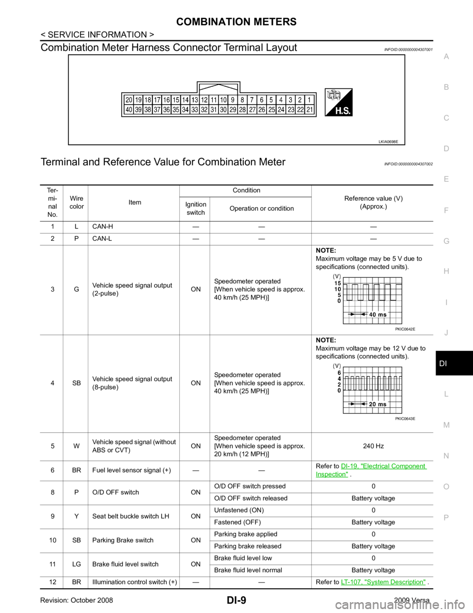
Combination Meter Harness Connector Terminal Layout
INFOID:0000000004307001
Terminal and Reference Va lue for Combination Meter INFOID:0000000004307002 Electrical Component
Inspection " .
8 P O/D OFF switch ON O/D OFF switch pressed 0
O/D OFF switch released Battery voltage
9 Y Seat belt buckle switch LH ON Unfastened (ON) 0
Fastened (OFF) Battery voltage
10 SB Parking Brake switch ON Parking brake applied 0
Parking brake released Battery voltage
11 LG Brake fluid level switch ON Brake fluid level low 0
Brake fluid level normal Battery voltage
12 BR Illumination control switch (+) — — Refer to LT-107, " System Description " .
Page 1315 of 4331

DI
N
O P
NOTE:
Some items are not available due to vehicle specification.
*: The monitor will indicate “OFF” even though the brake warnin g lamp is on if either of the following conditions exist.
• The parking brake is engaged
• The brake fluid level is low
Trouble Diagnosis INFOID:0000000004307005
HOW TO PERFORM TROUBLE DIAGNOSIS 1. Confirm the symptom or customer complaint.
2. Perform preliminary check. Refer to "PRELIMINARY CHECK" .
3. According to the symptom chart, repair or replace the cause of the malfunction. Refer to DI-14, " Symptom
Chart " .
4. Does the meter operate normally? If so, GO TO 5. If not, GO TO 2.
5. Inspection End.
PRELIMINARY CHECK Self-Diagnosis Mode of Combination Meter " .
Does self - diagnosis mode operate?
YES >> GO TO 2.
TURN IND [ON/OFF] X Indicates [ON/O
FF] condition of turn indicator.
OIL W/L [ON/OFF] X Indicates [ON/OFF] condition of oil pressure warning lamp.
ABS W/L [ON/OFF] X Indicates [ON/O FF] condition of ABS warning lamp.
BRAKE W/L [ON/OFF] X Indicates [ON/OFF] condition of brake warning lamp.*
KEY G W/L [ON/OFF] X Indicates [ON/OFF] condition of KEY warning lamp (green).
KEY R W/L [ON/OFF] X Indicates [ON/OFF] condition of KEY warning lamp (red).
KEY KNOB W/L [ON/OFF] X Indicates [ON/OFF] condition of LOCK warning lamp.
PNP P SW [ON/OFF] X X Indicates [ON/OFF] condition of inhibitor P switch.
PNP N SW [ON/OFF] X X Indicates [ON/OFF] condition of inhibitor N switch.
O/D OFF SW [ON/OFF] X Indicates [ON/ OFF] condition of O/D OFF switch.
BRAKE SW [ON/OFF] X Indicates [ON/OFF] condition of parking brake switch.
P RANGE IND [ON/OFF] X X Indicates [ON/OFF] condition of A/T or CVT shift P range indi-
cator.
R RANGE IND [ON/OFF] X X Indicates [ON/OFF] condition of A/T or CVT shift R range indi-
cator.
N RANGE IND [ON/OFF] X X Indicates [ON/OFF] condition of A/T or CVT shift N range indi-
cator.
D RANGE IND [ON/OFF] X X Indicates [ON/OFF] condition of A/T or CVT shift D range indi-
cator.
2 RANGE IND [ON/OFF] X X Indicates [ON/OFF] condition of A/T shift 2 range indicator.
L RANGE IND [ON/OFF] X X Indicates [ON/OFF] condition of CVT shift L range indicator.
1 RANGE IND [ON/OFF] X X Indicates [ON/OFF] condition of A/T shift 1 range indicator.
CRUISE IND [ON/OFF] X Indicates [ON/O FF] condition of CRUISE indicator.
SET IND [ON/OFF] X Indicates [ON/OFF] condition of SET indicator.
O/D OFF W/L [ON/OFF] X Indicates [ON/OFF] condition of O/D OFF indicator lamp.
e-4WD W/L [ON/OFF] X This item is not used for this model. “OFF” is always displayed.
EPS W/L [ON/OFF] X Indicates [ON/O FF] condition of EPS warning lamp.
Display item [Unit]
MAIN
SIGNALS SELECTION
FROM MENU Contents
Page 1350 of 4331
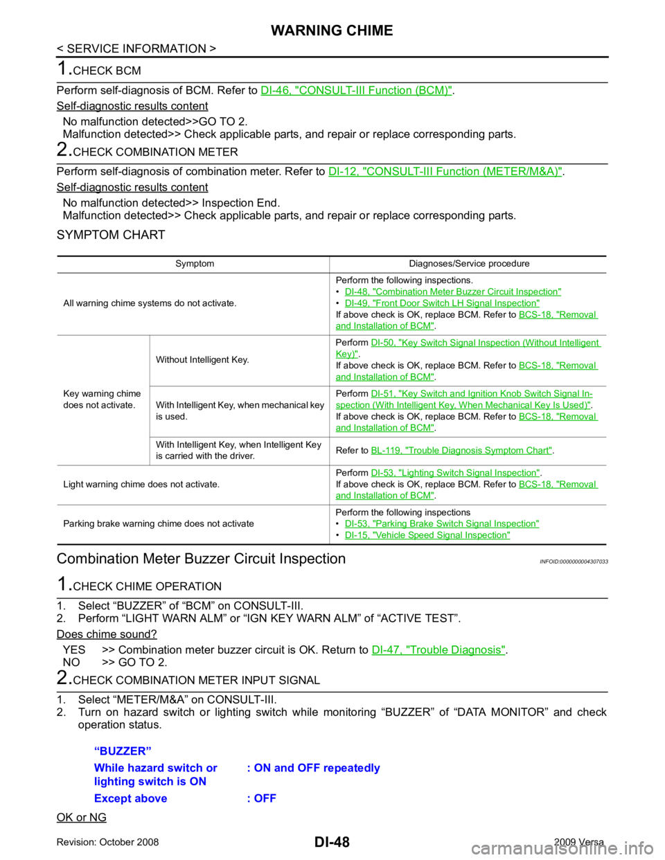
CONSULT-III Function (BCM) " .
Self - diagnostic results content
No malfunction detected>>GO TO 2.
Malfunction detected>> Check applicable parts, and repair or replace corresponding parts. CONSULT-III Function (METER/M&A) " .
Self - diagnostic results content
No malfunction detected>> Inspection End.
Malfunction detected>> Check applicable parts, and repair or replace corresponding parts.
SYMPTOM CHART
Combination Meter Buzzer Circuit Inspection INFOID:0000000004307033YES >> Combination meter buzzer circuit is OK. Return to
DI-47, " Trouble Diagnosis " .
NO >> GO TO 2. Combination Meter Buzzer Circuit Inspection "
•
DI-49, " Front Door Switch LH Signal Inspection "
If above check is OK, replace BCM. Refer to
BCS-18, " Removal
and Installation of BCM " .
Key warning chime
does not activate. Without Intelligent Key.
Perform
DI-50, " Key Switch Signal Inspection (Without Intelligent
Key) " .
If above check is OK, replace BCM. Refer to BCS-18, " Removal
and Installation of BCM " .
With Intelligent Key, when mechanical key
is used. Perform
DI-51, " Key Switch and Ignition Knob Switch Signal In-
spection (With Intelligent Key, When Mechanical Key Is Used) " .
If above check is OK, replace BCM. Refer to BCS-18, " Removal
and Installation of BCM " .
With Intelligent Key, when Intelligent Key
is carried with the driver. Refer to
BL-119, " Trouble Diagnosis Symptom Chart " .
Light warning chime does not activate. Perform
DI-53, " Lighting Switch Signal Inspection " .
If above check is OK, replace BCM. Refer to BCS-18, " Removal
and Installation of BCM " .
Parking brake warning chime does not activate Perform the following inspections
• DI-53, " Parking Brake Switch Signal Inspection "
•
DI-15, " Vehicle Speed Signal Inspection "