parking brake NISSAN LATIO 2009 Service User Guide
[x] Cancel search | Manufacturer: NISSAN, Model Year: 2009, Model line: LATIO, Model: NISSAN LATIO 2009Pages: 4331, PDF Size: 58.04 MB
Page 837 of 4331
BR
N
O P
5. Connect the parking brake rear cable to the operating lever.
6. Install the shoe assembly. After assembly, be sure that each part is installed properly. CAUTION:
Do not damage the wheel cylinder piston boot.
7. Install the brake drum.
8. Depress brake pedal for several times (approximately 2 or 3 times).
9. Adjust clearance of brake shoe. Refer to PB-5, " On-Vehicle Service " .
10. Install rear wheel and tire. Refer to WT-7, " Rotation " .
Removal and Installati on of Wheel Cylinder INFOID:0000000004305917
REMOVAL 1. Drain the brake fluid. Refer to BR-9, " Drain and Refill " .
2. Remove the rear brake shoe assembly. Refer to BR-34, " Removal and Installation of Drum Brake Assem-
bly " .
3. Remove the bleed valve.
4. Disconnect the brake tube from the wheel cylinder.
5. Remove the wheel cylinder bolts and then remo ve the wheel cylinder from the back plate.
INSTALLATION Installation is in the reverse order of removal.
• Tighten bolts and bleed valve to the specified torque. Refer to BR-33, " Component " .
• Refill with new brake fluid and bleed the air. Refer to BR-9, " Bleeding Brake System " .
Disassembly and Assemb ly of Wheel Cylinder INFOID:0000000004305918
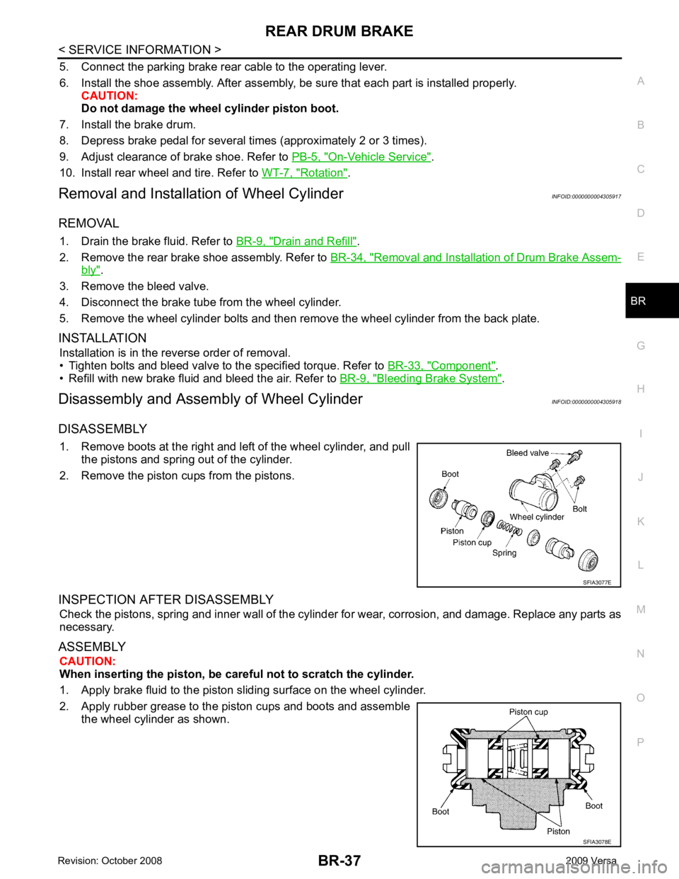
DISASSEMBLY 1. Remove boots at the right and left of the wheel cylinder, and pull the pistons and spring out of the cylinder.
2. Remove the piston cups from the pistons.
INSPECTION AFTER DISASSEMBLY Check the pistons, spring and inner wall of the cylinder for wear, corrosion, and damage. Replace any parts as
necessary.
ASSEMBLY CAUTION:
When inserting the piston, be caref ul not to scratch the cylinder.
1. Apply brake fluid to the piston sliding surface on the wheel cylinder.
2. Apply rubber grease to the piston cups and boots and assemble the wheel cylinder as shown.
Page 857 of 4331
BRC
N
O P
• If ABS actuator and electric unit (control unit) connec
tion is loose, tighten the piping to the specified
torque and recheck for leaks.
• If there is damage to the connection flare nut or A BS actuator and electric unit (control unit) threads,
replace the damaged part and recheck for leaks.
• When there is fluid leaking or seeping from a fluid connection, use a clean cloth to wipe off the fluid and recheck for leaks. If fluid is still seeping out, repl ace the damaged part. If the fluid is leaking at the ABS
actuator and electric unit (control unit), replace the ABS actuator and electric unit (control unit) assem-
bly.
CAUTION:
The ABS actuator and electric unit (control un it) cannot be disassembled and must be replaced
as an assembly.
3. Check the brake pads for excessive wear.
POWER SYSTEM TERMINAL LOOSENESS AND BATTERY INSPECTION Make sure the battery positive cable, negative cabl e and ground connection are not loose. In addition, make
sure the battery is sufficiently charged.
ABS WARNING LAMP INSPECTION 1. Make sure ABS warning lamp turns on for approximately 2 seconds when the ignition switch is turned ON. If it does not, check CAN communications. If ther e are no errors with the CAN communication system,
replace the combination meter. Refer to IP-12, " Removal and Installation " .
2. Make sure the lamp turns off approximately 2 seconds after the ignition switch is turned ON. If the lamp does not turn off, conduct self-diagnosis of ABS act uator and electric unit (control unit). If no malfunctions
are detected in self-diagnosis, replace combination meter. Refer to IP-12, " Removal and Installation " .
3. After conducting the self-diagnosis, be sure to erase the error memory. Refer to BRC-18, " CONSULT-III
Function (ABS) " .
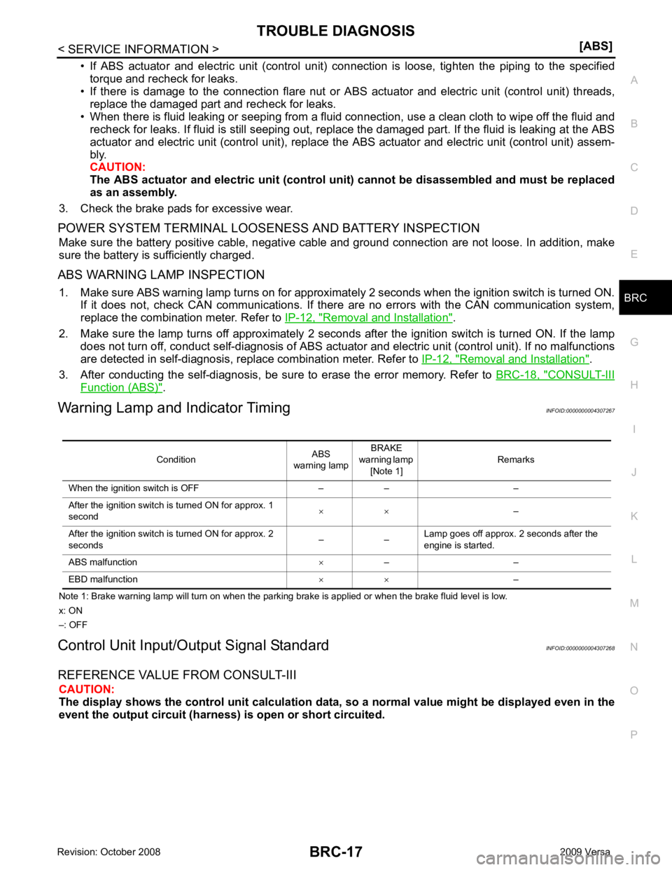
Warning Lamp and Indicator Timing INFOID:0000000004307267
Note 1: Brake warning lamp will turn on when the parking brake is applied or when the brake fluid level is low.
x: ON
–: OFF
Control Unit Input/Out put Signal Standard INFOID:0000000004307268
REFERENCE VALUE FROM CONSULT-III CAUTION:
The display shows the control unit calculation data, so a normal value might be displayed even in the
event the output circuit (harness) is open or short circuited.
Condition
ABS
warning lamp BRAKE
warning lamp [Note 1] Remarks
When the ignition switch is OFF – – –
After the ignition switch is turned ON for approx. 1
second × ×
–
After the ignition switch is turned ON for approx. 2
seconds – –Lamp goes off approx. 2 seconds after the
engine is started.
ABS malfunction ×– –
EBD malfunction × ×–
Page 961 of 4331
CVT
N
O P
CVT FLUID
Checking CVT Fluid INFOID:0000000004666862
FLUID LEVEL CHECK Fluid level should be checked with the fluid warmed up to 50 ° to 80 °C (122 ° to 176 °F).
1. Check for fluid leakage.
2. With the engine warmed up, drive the vehicle to warm up the CVT fluid. When ambient temperature is 20 °C (68 °F), it takes
about 10 minutes for the CVT fluid to warm up to 50 ° to 80 °C
(122 ° to 176 °F).
3. Park the vehicle on a level surface and set the parking brake.
4. With engine at idle, while depressing brake pedal, move the selector lever throughout the entire shift range and return it to
the “P” position.
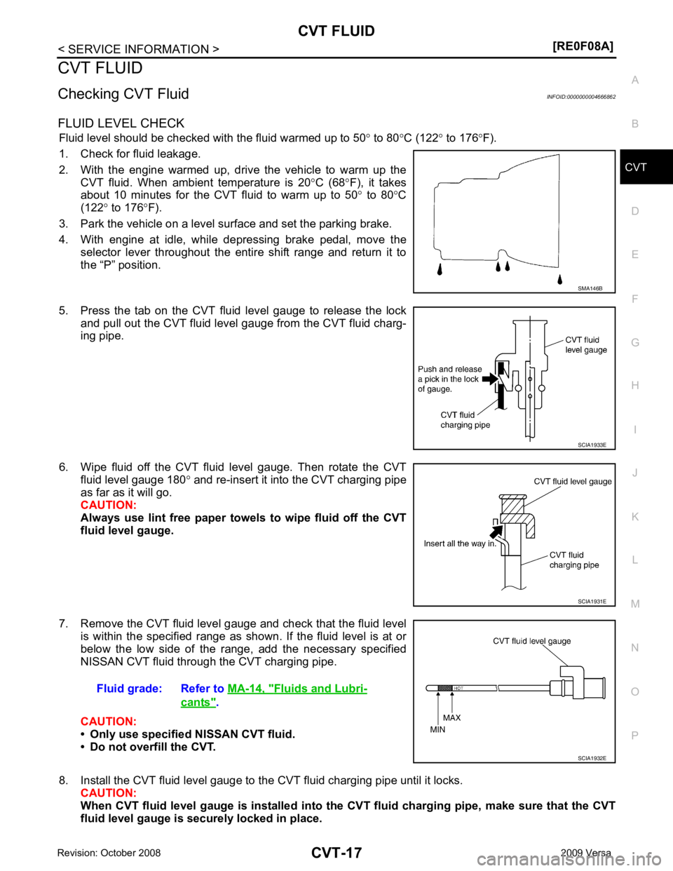
5. Press the tab on the CVT fluid level gauge to release the lock and pull out the CVT fluid level gauge from the CVT fluid charg-
ing pipe.
6. Wipe fluid off the CVT fluid level gauge. Then rotate the CVT fluid level gauge 180 ° and re-insert it into the CVT charging pipe
as far as it will go.
CAUTION:
Always use lint free paper towels to wipe fluid off the CVT
fluid level gauge.
7. Remove the CVT fluid level gauge and check that the fluid level is within the specified range as shown. If the fluid level is at or
below the low side of the range, add the necessary specified
NISSAN CVT fluid through the CVT charging pipe.
CAUTION:
• Only use specified NISSAN CVT fluid.
• Do not overfill the CVT.
8. Install the CVT fluid level gauge to the CVT fluid charging pipe until it locks. CAUTION:
When CVT fluid level gauge is installed into the CVT fluid charging pipe, make sure that the CVT
fluid level gauge is securely locked in place. Fluids and Lubri-
cants " .
Page 985 of 4331
![NISSAN LATIO 2009 Service User Guide TROUBLE DIAGNOSIS
CVT-41
< SERVICE INFORMATION >
[RE0F08A] D
E
F
G H
I
J
K L
M A
B CVT
N
O P
• Inspect for fluid leakage and check the fluid level. Refer to
CVT-17, " Checking CVT Fluid " .
Fluid](/img/5/57359/w960_57359-984.png "NISSAN LATIO 2009 Service User Guide TROUBLE DIAGNOSIS
CVT-41
< SERVICE INFORMATION >
[RE0F08A] D
E
F
G H
I
J
K L
M A
B CVT
N
O P
• Inspect for fluid leakage and check the fluid level. Refer to
CVT-17, \" Checking CVT Fluid \" .
Fluid")
TROUBLE DIAGNOSIS
CVT-41
< SERVICE INFORMATION >
[RE0F08A] D
E
F
G H
I
J
K L
M A
B CVT
N
O P
• Inspect for fluid leakage and check the fluid level. Refer to
CVT-17, " Checking CVT Fluid " .
Fluid Condition Check Inspect the fluid condition.
STALL TEST
Stall Test Procedure 1. Inspect the amount of engine oil. Replenish the engine oil if necessary.
2. Drive for about 10 minutes to warm up the vehicle so that the CVT fluid temperature is 50 to 80 °C (122 to 176 °F). Inspect the
amount of CVT fluid. Replenish if necessary.
3. Securely engage the parking brake so that the tires do not turn.
4. Install a tachometer where it can be seen by driver during test. •It is good practice to mark the point of specified engine
rpm on indicator.
5. Start engine, apply foot brake, and place selector lever in “D” position.Fluid status Conceivable cause Required operation
Varnished (viscous
varnish state) Clutch, brake
scorched Replace the CVT fluid and check the
CVT main unit and the vehicle for
malfunctions (wire harnesses, cool-
er pipes, etc.)
Milky white or
cloudy Water in the fluidReplace the CVT fluid and check for
places where water is getting in.
Large amount of
metal powder mixed
in Unusual wear of
sliding parts within
CVT Replace the CVT fluid and check for
improper operation of the CVT. SAT638A
SAT647B
SAT513G
SAT775B
Page 987 of 4331
CVT
N
O P
The CVT fluid temperature rises in the range of 50 - 80
°C (122 - 176 °F) during 10 minutes of driving.
3. After warming up CVT, remove the oil pressure detection plug and install the oil pressure gauge [special service tool: - (OTC3492)].
CAUTION:
When using the oil pressure gauge, be sure to use the O-ring attached to the oil pressure detec-
tion plug.
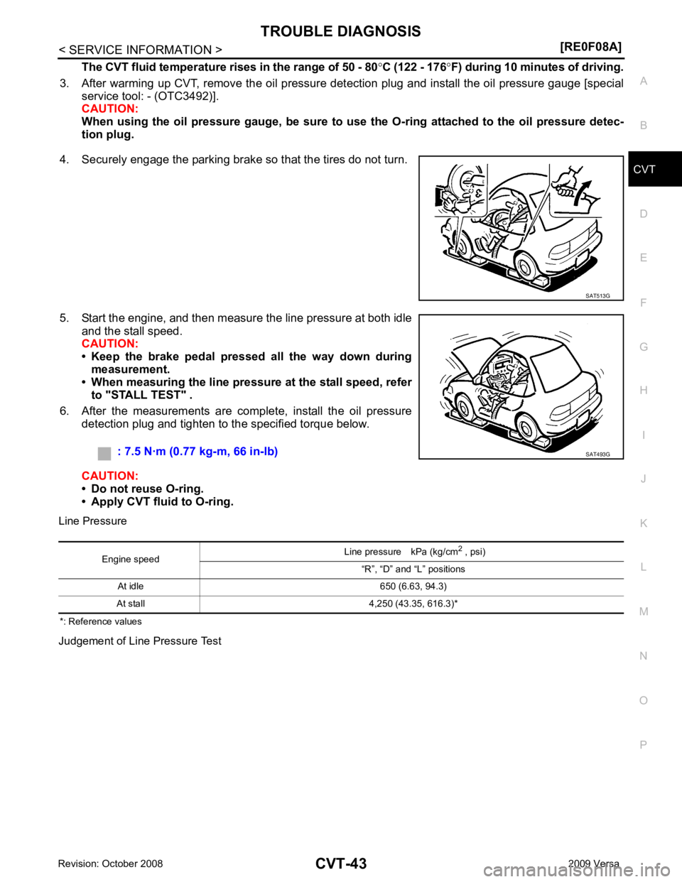
4. Securely engage the parking brake so that the tires do not turn.
5. Start the engine, and then measure the line pressure at both idle and the stall speed.
CAUTION:
• Keep the brake pedal pressed all the way down during
measurement.
• When measuring the line pressure at the stall speed, refer
to "STALL TEST" .
6. After the measurements are complete, install the oil pressure detection plug and tighten to the specified torque below.
CAUTION:
• Do not reuse O-ring.
• Apply CVT fluid to O-ring.
Line Pressure
*: Reference values
Judgement of Line Pressure Test
Page 1118 of 4331
![NISSAN LATIO 2009 Service User Guide CVT-174< SERVICE INFORMATION >
[RE0F08A]
SHIFT CONTROL SYSTEM
• When installing the control cable (1) to the control device assembly (2), make sure that the control cable (1) is fully pressed in wit](/img/5/57359/w960_57359-1117.png "NISSAN LATIO 2009 Service User Guide CVT-174< SERVICE INFORMATION >
[RE0F08A]
SHIFT CONTROL SYSTEM
• When installing the control cable (1) to the control device assembly (2), make sure that the control cable (1) is fully pressed in wit")
CVT-174< SERVICE INFORMATION >
[RE0F08A]
SHIFT CONTROL SYSTEM
• When installing the control cable (1) to the control device assembly (2), make sure that the control cable (1) is fully pressed in with the
ribbed surface (A) facing downward from the vehicle.
: Vehicle front
• After installation is completed, adjust and check the CVT position.
Refer to CVT-175, " Adjustment of CVT Position " and
CVT-175, " Checking of CVT Position " .
Control Device Disassembly and Assembly INFOID:0000000004667109
DISASSEMBLY
NOTE:
Refer to CVT-171, " Removal and Installation " to disassemble.
1. Remove selector lever knob from control device assembly. Refer to CVT-174, " Selector Lever Knob
Removal and Installation " .
2. Remove position lamp from position indicator plate (1).
3. Insert a suitable tool to (A) (at 4 locations) as shown, and bend each hook slightly to raise position indicator plate (1) and
remove from control device assembly (2).
4. Remove bracket from control device assembly (2).
5. Remove CVT device harness c onnector from control device
assembly (2).
6. Release tabs (A) on shift lock solenoid and park position switch assembly from hooks (B) on control device assembly to shift
lock solenoid and park position switch assembly.
ASSEMBLY
Assembly is in the reverse order of disassembly.
Selector Lever Knob Re moval and Installation INFOID:0000000004667110
REMOVAL
CAUTION:
Make sure that parking brake is applied before removal/installation. SCIA6253E
SCIA6969E
SCIA6977E
Page 1119 of 4331
![NISSAN LATIO 2009 Service User Guide SHIFT CONTROL SYSTEM
CVT-175
< SERVICE INFORMATION >
[RE0F08A] D
E
F
G H
I
J
K L
M A
B CVT
N
O P
1. Set selector lever knob (1) in “N” position.
2. Slide knob cover (2) downward.
3. Pull out lock](/img/5/57359/w960_57359-1118.png "NISSAN LATIO 2009 Service User Guide SHIFT CONTROL SYSTEM
CVT-175
< SERVICE INFORMATION >
[RE0F08A] D
E
F
G H
I
J
K L
M A
B CVT
N
O P
1. Set selector lever knob (1) in “N” position.
2. Slide knob cover (2) downward.
3. Pull out lock")
SHIFT CONTROL SYSTEM
CVT-175
< SERVICE INFORMATION >
[RE0F08A] D
E
F
G H
I
J
K L
M A
B CVT
N
O P
1. Set selector lever knob (1) in “N” position.
2. Slide knob cover (2) downward.
3. Pull out lock pin (3) from selector lever knob (1).
4. Remove selector lever knob (1) and knob cover (2) as a set from selector lever.
CAUTION:
Do not push selector button.
INSTALLATION 1. Insert lock pin (1) to selector lever knob (2).
2. Install knob cover (3) to selector lever knob (2).
3. Set selector lever in “N” position.
4. Install selector lever knob onto selector lever until a click is felt. CAUTION:
• Do not tilt selector lever knob when installing. Install it
straight, and do not tap or ap ply any shock to install it.
• Do not push selector button.
Adjustment of CVT Position INFOID:0000000004667111
CAUTION:
Make sure that parking brake is applied before adjustment.
1. Loosen the control cable nut (A) and place the manual lever (1) in “P” position.
2. Place selector lever in “P” position.
3. Push the control cable (2) in with a load of 9.8 N (approximately 1 kg, 2.2 lb). Release the control cable and temporarily tighten
the control cable nut.
NOTE:
Do not move the manual lever. Make sure the manual lever
stays in the “P” position.
4. Tighten the control cable nut. CAUTION:
Secure the manual lever when tightening nut.
5. Check the operation of the CVT. Refer to CVT-175, " Checking of CVT Position " .
Checking of CVT Position INFOID:0000000004667112
1. Place selector lever in “P” position, and tu rn ignition switch ON. (Do not start engine.)
2. Make sure selector lever can be shifted to other than “P” position when brake pedal is depressed. Also
make sure selector lever can be shifted from “P” position only when brake pedal is depressed.
3. Move the selector lever and check for excessive effort, sticking, noise or rattle.
4. Confirm the selector lever stops at each position with the feel of engagement when it is moved through all
the positions. Check that t he actual position of the selector lever matches the position shown by the shift
position indicator and the manual lever on the transaxle. SCIA6971E
SCIA6972E
Control cable nut: Refer to
CVT-171, " Removal
and Installation " . WCIA0608E
Page 1121 of 4331
![NISSAN LATIO 2009 Service User Guide KEY INTERLOCK CABLE
CVT-177
< SERVICE INFORMATION >
[RE0F08A] D
E
F
G H
I
J
K L
M A
B CVT
N
O P
KEY INTERLOCK CABLE
Removal and Installation INFOID:0000000004667113
COMPONENTS
REMOVAL Refer to the fig](/img/5/57359/w960_57359-1120.png "NISSAN LATIO 2009 Service User Guide KEY INTERLOCK CABLE
CVT-177
< SERVICE INFORMATION >
[RE0F08A] D
E
F
G H
I
J
K L
M A
B CVT
N
O P
KEY INTERLOCK CABLE
Removal and Installation INFOID:0000000004667113
COMPONENTS
REMOVAL Refer to the fig")
KEY INTERLOCK CABLE
CVT-177
< SERVICE INFORMATION >
[RE0F08A] D
E
F
G H
I
J
K L
M A
B CVT
N
O P
KEY INTERLOCK CABLE
Removal and Installation INFOID:0000000004667113
COMPONENTS
REMOVAL Refer to the figure for key interlock cable removal procedure.
CAUTION:
Make sure that parking brake is a pplied before removal/installation.
1. Place the selector lever in the “N” position.
2. Remove the selector lever knob. Refer to CVT-174, " Selector Lever Knob Removal and Installation " .
3. Remove the center console assembly. Refer to IP-11 .
1. Key interlock cable 2. Key cylinder 3. Control device assembly
A. Lock plate B. Holder C. Clip
D. Slider E. Key interlock rod F. Adjust holder
G. Casing cap WCIA0621E
Page 1140 of 4331
![NISSAN LATIO 2009 Service User Guide CVT-196< SERVICE INFORMATION >
[RE0F08B]
CVT FLUID
CVT FLUID
Checking CVT Fluid INFOID:0000000004305570
FLUID LEVEL CHECK
Fluid level should be checked with the fluid warmed up to 50 ° to 80 °C (122](/img/5/57359/w960_57359-1139.png "NISSAN LATIO 2009 Service User Guide CVT-196< SERVICE INFORMATION >
[RE0F08B]
CVT FLUID
CVT FLUID
Checking CVT Fluid INFOID:0000000004305570
FLUID LEVEL CHECK
Fluid level should be checked with the fluid warmed up to 50 ° to 80 °C (122")
CVT-196< SERVICE INFORMATION >
[RE0F08B]
CVT FLUID
CVT FLUID
Checking CVT Fluid INFOID:0000000004305570
FLUID LEVEL CHECK
Fluid level should be checked with the fluid warmed up to 50 ° to 80 °C (122 ° to 176 °F).
1. Check for fluid leakage.
2. With the engine warmed up, drive the vehicle to warm up the CVT fluid. When ambient temperature is 20 °C (68 °F), it takes
about 10 minutes for the CVT fluid to warm up to 50 ° to 80 °C
(122 ° to 176 °F).
3. Park the vehicle on a level surface and set the parking brake.
4. With engine at idle, while depressing brake pedal, move the selector lever throughout the entire shift range and return it to
the “P” position.
5. Press the tab on the CVT fluid level gauge to release the lock and pull out the CVT fluid level gauge from the CVT fluid charg-
ing pipe.
6. Wipe fluid off the CVT fluid level gauge. Then rotate the CVT fluid level gauge 180 ° and re-insert it into the CVT charging pipe
as far as it will go.
CAUTION:
Always use lint free paper towels to wipe fluid off the CVT
fluid level gauge.
7. Remove the CVT fluid level gauge and check that the fluid level is within the specified range as shown. If the fluid level is at or
below the low side of the range, add the necessary specified
NISSAN CVT fluid through the CVT charging pipe.
CAUTION:
• Only use specified NISSAN CVT fluid.
• Do not overfill the CVT.
8. Install the CVT fluid level gauge to the CVT fluid charging pipe until it locks. CAUTION:
When CVT fluid level gauge is in stalled into the CVT fluid charging pipe, make sure that the CVT
fluid level gauge is securely locked in place. SMA146B
SCIA1933E
SCIA1931E
Fluid grade: Refer to
MA-14, " Fluids and Lubri-
cants " .
SCIA1932E
Page 1145 of 4331
![NISSAN LATIO 2009 Service User Guide CVT SYSTEM
CVT-201
< SERVICE INFORMATION >
[RE0F08B] D
E
F
G H
I
J
K L
M A
B CVT
N
O P
CVT SYSTEM
Cross-Sectional View - RE0F08B INFOID:0000000004305573
1. Converter housing 2. Oil pump 3. Forward clu](/img/5/57359/w960_57359-1144.png "NISSAN LATIO 2009 Service User Guide CVT SYSTEM
CVT-201
< SERVICE INFORMATION >
[RE0F08B] D
E
F
G H
I
J
K L
M A
B CVT
N
O P
CVT SYSTEM
Cross-Sectional View - RE0F08B INFOID:0000000004305573
1. Converter housing 2. Oil pump 3. Forward clu")
CVT SYSTEM
CVT-201
< SERVICE INFORMATION >
[RE0F08B] D
E
F
G H
I
J
K L
M A
B CVT
N
O P
CVT SYSTEM
Cross-Sectional View - RE0F08B INFOID:0000000004305573
1. Converter housing 2. Oil pump 3. Forward clutch
4. Reverse brake 5. Planetary carrier 6. Primary pulley
7. Steel belt 8. Sun gear 9. Side cover
10. Internal gear 11. Secondary pulley 12. Differential case
13. Final gear 14. Idler gear 15. Reduction gear
16. Output gear 17. Parking gear 18. Input shaft
19. Torque converter SCIA8015E