ground NISSAN LATIO 2009 Service Manual PDF
[x] Cancel search | Manufacturer: NISSAN, Model Year: 2009, Model line: LATIO, Model: NISSAN LATIO 2009Pages: 4331, PDF Size: 58.04 MB
Page 484 of 4331

BL
N
O P
System Description
INFOID:0000000004304987
Power is supplied at all times
• through 40A fusible link (letter g , located in the fuse and fusible link box)
• to BCM terminal 70
• through 10A fuse [No. 8, located in the fuse block (J/B)]
• to BCM terminal 57
• through 10A fuse [No. 14, located in the fuse block (J/B)]
• to key switch terminal 2 (without Intelligent Key system)
• through 10A fuse [No. 31, located in the fuse block (J/B)]
• to key switch and ignition knob switch terminals 2 and 4 (with Intelligent Key system).
When key switch is ON (key is inserted in ignition key cylinder), power is supplied
• through key switch terminal 1 (without Intelligent Key system) or key switch and ignition knob terminal 1 (with Intelligent Key system)
• to BCM terminal 37.
Ground is supplied
• to BCM terminal 67
• through body grounds M57 and M61.
LOCK OPERATION When the door is locked with main power window and door lock/unlock switch, ground is supplied
• to BCM terminal 45
• through main power window and door lock and unlock switch terminals 17 and 18
• through body grounds M57 and M61.
When the door is locked with power window and door lock/unlock switch RH, ground is supplied
• to BCM terminal 45
• through power window and door lock and unlock switch RH terminals 1 and 3
• through body grounds M57 and M61.
When the door is locked with front door ke y cylinder switch LH, ground is supplied
• to BCM terminal 8
• through front door key cylinder switch LH terminals 1 and 2
• through body grounds M57 and M61.
UNLOCK OPERATION When the door is unlocked with main power window and door lock/unlock switch, ground is supplied
• to BCM terminal 46
• through main power window and door lock/unlock switch terminals 6 and 17
• through body grounds M57 and M61.
When the door is unlocked with power window and door lock/unlock switch RH, ground is supplied
• to BCM terminal 46
• through power window and door lock and unlock switch RH terminals 2 and 3
• through body grounds M57 and M61.
When the door is unlocked with front door ke y cylinder switch LH, ground is supplied
• to BCM terminal 7
• through front door key cylinder switch LH terminals 2 and 3
• through body grounds M57 and M61.
When the front door switch LH is ON (door is OPEN), ground is supplied
• to BCM terminal 47
• through front door switch LH terminal 2
• through front door switch LH case ground.
When the front door switch RH is ON (door is OPEN), ground is supplied
• to BCM terminal 12
• through front door switch RH terminal 2
• through front door switch RH case ground. 10. Key switch and key lock solenoid M27
(without Intelligent key) 11. Main power window and door lock/un-
lock switch D7, D8
Power window and door lock/unlock
switch RH D105 12. Fuse block (with Intelligent Key)
(view with instrument panel LH re-
moved)
13. Passenger select unlock relay M2 (with Intelligent Key) 14. Back door lock assembly (back door
switch) D405 (hatchback view with back
door open) 15. Combination meter M24
Page 499 of 4331
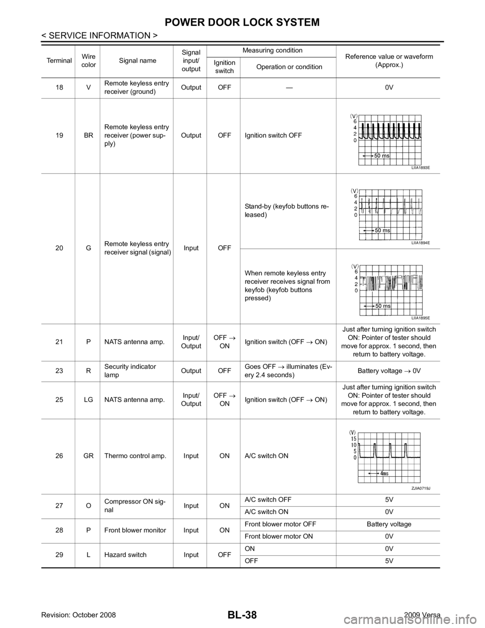
BL-38< SERVICE INFORMATION >
POWER DOOR LOCK SYSTEM
18 V Remote keyless entry
receiver (ground) Output OFF — 0V
19 BR Remote keyless entry
receiver (power sup-
ply) Output OFF Ignition switch OFF
20 G Remote keyless entry
receiver signal (signal) Input OFFStand-by (keyfob buttons re-
leased)
When remote keyless entry
receiver receives signal from
keyfob (keyfob buttons
pressed)
21 P NATS antenna amp. Input/
Output OFF
→
ON Ignition switch (OFF
→ ON) Just after turning ignition switch
ON: Pointer of tester should
move for approx. 1 second, then return to battery voltage.
23 R Security indicator
lamp Output OFFGoes OFF
→ illuminates (Ev-
ery 2.4 seconds) Battery voltage
→ 0V
25 LG NATS antenna amp. Input/
Output OFF
→
ON Ignition switch (OFF
→ ON) Just after turning ignition switch
ON: Pointer of tester should
move for approx. 1 second, then
return to battery voltage.
26 GR Thermo control amp. Input ON A/C switch ON
27 O Compressor ON sig-
nal Input ONA/C switch OFF 5V
A/C switch ON 0V
28 P Front blower monitor Input ON Front blower motor OFF Battery voltage
Front blower motor ON 0V
29 L Hazard switch Input OFF ON 0V
OFF 5V
Terminal
Wire
color Signal name Signal
input/
output Measuring condition
Reference value or waveform
(Approx.)
Ignition
switch Operation or condition LIIA1893E
LIIA1894E
LIIA1895E
ZJIA0719J
Page 502 of 4331

BL
N
O P
1: With Intelligent Key
2: Without Intelligent Key
3: Hatchback without Intelligent Key
4: Sedan without Intelligent Key
5: Hatchback
6: Sedan
7: With power door locks
8: With power windows
Work Flow INFOID:0000000004304994
1. Check the symptom and customer's requests.
2. Understand the outline of system. Refer to BL-23, " System Description " .
3. According to the trouble diagnosis chart, repair or replace the cause of the malfunction. Refer to BL-119," Trouble Diagnosis Symptom Chart " .
4. Does power door lock system operate normally? OK: GO TO 5, NG: GO TO 3.
5. Inspection End.
CONSULT-III Function (BCM) INFOID:0000000004304995
CONSULT-III can display each diagnostic item using the diagnostic test modes shown following. 65
7
SBAll door lock actuators
(lock) Output OFFOFF (neutral) 0V
ON (lock) Battery voltage
66 7
GFront door lock actua-
tor RH, rear door lock
actuators LH/RH (un-
lock) Output OFFOFF (neutral) 0V
ON (unlock) Battery voltage
67 B Ground Input ON — 0V
68 8
LPower window power
supply (RAP) Output —Ignition switch ON Battery voltage
Within 45 seconds after igni-
tion switch OFF Battery voltage
More than 45 seconds after ig-
nition switch OFF 0V
When front door LH or RH is
open or power window timer
operates 0V
69 8
P Battery power supply
OutputOFF
— Battery voltage
70 Y Battery power supply Input OFF — Battery voltage
Terminal
Wire
color Signal name Signal
input/
output Measuring condition
Reference value or waveform
(Approx.)
Ignition
switch Operation or condition
Page 504 of 4331
BL
N
O P
*: With Remote Keyless Entry system
**: With Intelligent Key system
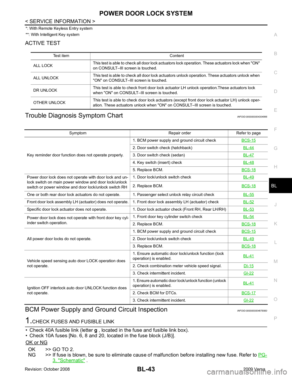
ACTIVE TEST
Trouble Diagnosis Symptom Chart INFOID:0000000004304996
BCM Power Supply and Gr ound Circuit Inspection INFOID:0000000004678560OK >> GO TO 2.
NG >> If fuse is blown, be sure to eliminate caus e of malfunction before installing new fuse. Refer to PG-3, " Schematic " .
Test item Content
ALL LOCK This test is able to check all door lock actuators lock operation. These actuators lock when "ON"
on CONSULT–III screen is touched.
ALL UNLOCK This test is able to check all door lock actuators unlock operation. These actuators unlock when
"ON" on CONSULT–III screen is touched.
DR UNLOCK This test is able to check front door lock actuator LH unlock operation.These actuators lock
when "ON" on CONSULT– III screen is touched.
OTHER UNLOCK This test is able to check door lock actuators (except front door lock actuator LH) unlock oper-
ation. These actuators unlock when "ON" on CONSULT–III screen is touched. Symptom Repair order Refer to page
Key reminder door function does not operate properly. 1. BCM power supply and ground circuit check
BCS-15 2. Door switch check (hatchback)
BL-44 3. Door switch check (sedan)
BL-47 4. Key switch (insert) check
BL-48 5. Replace BCM.
BCS-18Power door lock does not operate with door lock and un-
lock switch on main power window and door lock/unlock
switch or power window and door lock/unlock switch RH 1. Door lock/unlock switch check
BL-49 2. Replace BCM.
BCS-18One or both rear door lock actuators do not operate. 1. Passenger select unlock relay circuit check
BL-55Front door lock assembly LH (actuator) does not operate. 1. Front door lock assembly LH (actuator) check
BL-52Specific door lock actuator does not operate. 1. Door lock actuator check (Front RH, Rear LH/RH)
BL-53Power door lock does not operate with front door key cyl-
inder switch operation. 1. Front door key cylinder switch check
BL-54 2. Replace BCM.
BCS-18All power door locks do not operate.
1. BCM power supply and ground circuit check
BCS-15 2. Door lock/unlock switch check
BL-49 3. Replace BCM.
BCS-18Vehicle speed sensing auto door LOCK operation does
not operate. 1. Ensure automatic door lock/unlock function (lock
operation) is enabled. BL-41 2. Check combination meter vehicle speed signal.
DI-15 3. Check intermittent incident.
GI-22Ignition OFF interlock auto door UNLOCK function does
not operate. 1. Ensure automatic door lock/unlock function (unlock
operation) is enabled. BL-41 2. Check BCM for DTCs.
BCS-17 3. Check intermittent incident.
GI-22
Page 505 of 4331
BL-44< SERVICE INFORMATION >
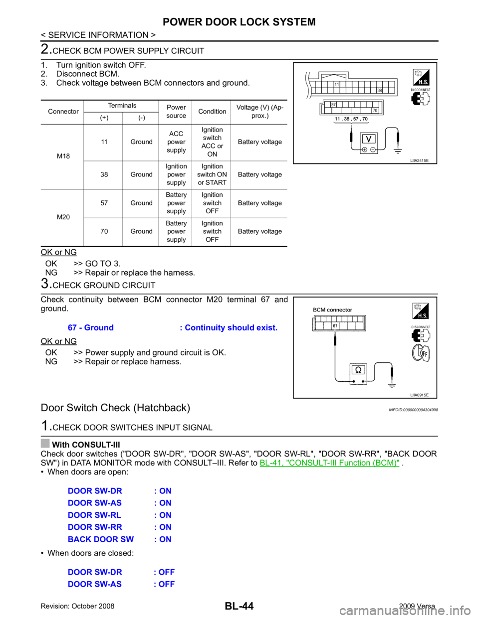
POWER DOOR LOCK SYSTEM2.
CHECK BCM POWER SUPPLY CIRCUIT
1. Turn ignition switch OFF.
2. Disconnect BCM.
3. Check voltage between BCM connectors and ground.
OK or NG OK >> GO TO 3.
NG >> Repair or replace the harness. 3.
CHECK GROUND CIRCUIT
Check continuity between BCM connector M20 terminal 67 and
ground.
OK or NG OK >> Power supply and ground circuit is OK.
NG >> Repair or replace harness.
Door Switch Check (Hatchback) INFOID:00000000043049981.
CHECK DOOR SWITCHES INPUT SIGNAL
With CONSULT-III
Check door switches ("DOOR SW-DR", "DOOR SW-AS", "DOOR SW-RL", "DOOR SW-RR", "BACK DOOR
SW") in DATA MONITOR mode with CONSULT–III. Refer to BL-41, " CONSULT-III Function (BCM) " .
• When doors are open:
• When doors are closed: Connector
Terminals
Power
source Condition Voltage (V) (Ap-
prox.)
(+) (-)
M18 11 Ground
ACC
power
supply Ignition
switch
ACC or ON Battery voltage
38 Ground Ignition
power
supply Ignition
switch ON
or START Battery voltage
M20 57 Ground
Battery
power
supply Ignition
switch OFF Battery voltage
70 Ground Battery
power
supply Ignition
switch OFF Battery voltage LIIA2415E
67 - Ground : Continuity should exist.
LIIA0915E
DOOR SW-DR : ON
DOOR SW-AS : ON
DOOR SW-RL : ON
DOOR SW-RR : ON
BACK DOOR SW : ON
DOOR SW-DR : OFF
DOOR SW-AS : OFF
Page 506 of 4331
BL
N
O P
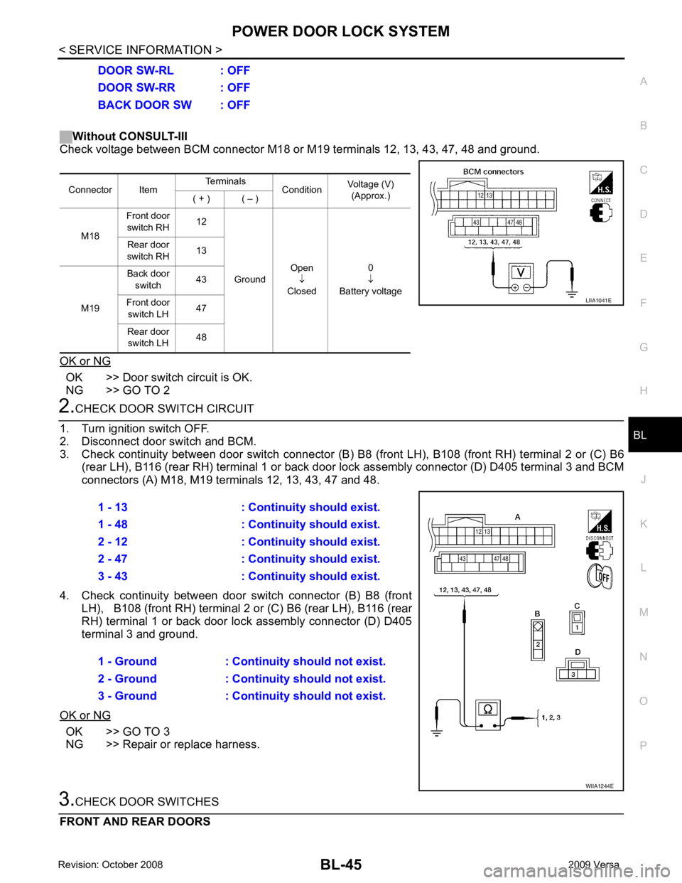
Without CONSULT-III
Check voltage between BCM connector M18 or M19 terminals 12, 13, 43, 47, 48 and ground.
OK or NG OK >> Door switch circuit is OK.
NG >> GO TO 2 OK >> GO TO 3
NG >> Repair or replace harness.
Page 508 of 4331
BL
N
O P
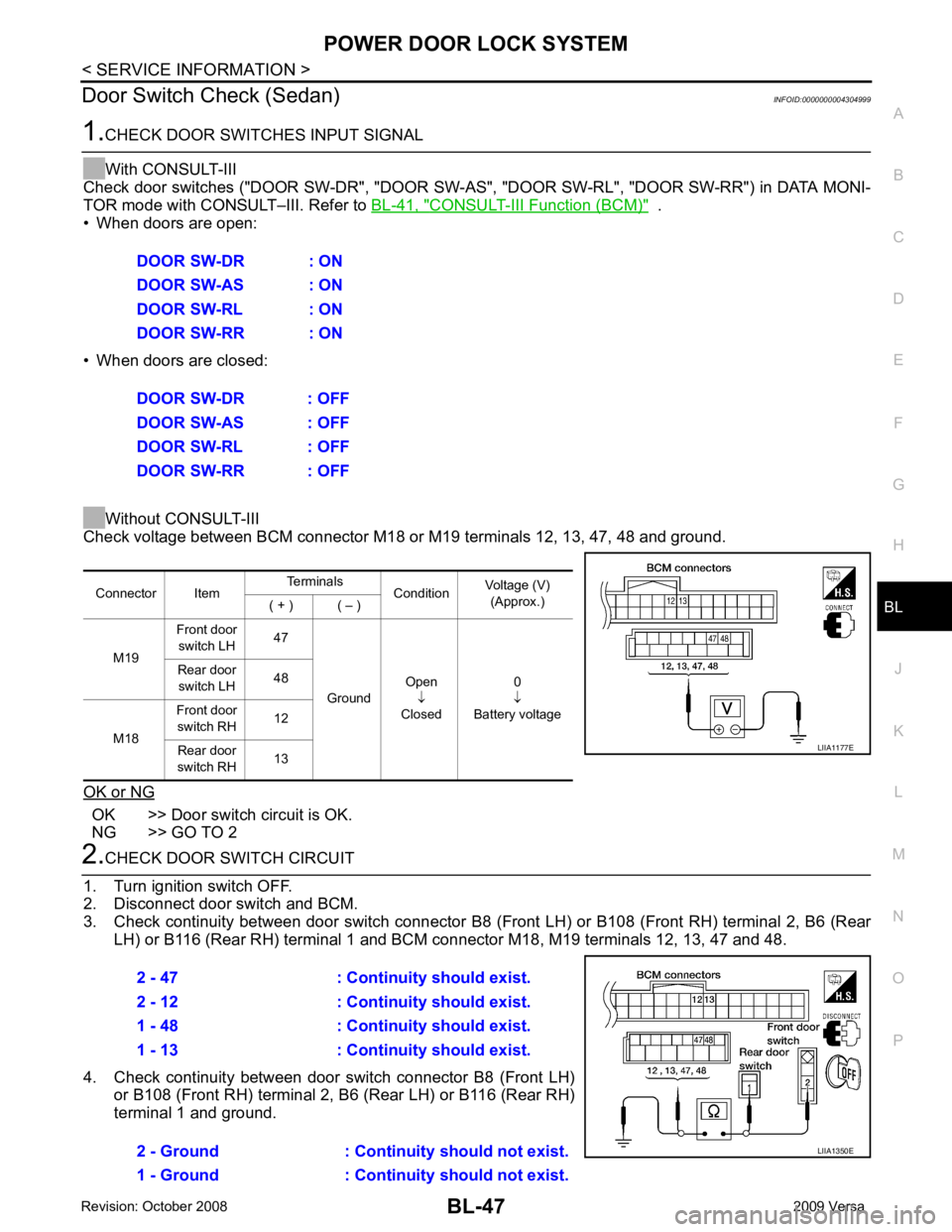
Door Switch Check (Sedan)
INFOID:0000000004304999CONSULT-III Function (BCM) " .
• When doors are open:
• When doors are closed:
Without CONSULT-III
Check voltage between BCM connector M18 or M19 terminals 12, 13, 47, 48 and ground.
OK or NG OK >> Door switch circuit is OK.
NG >> GO TO 2
Page 509 of 4331
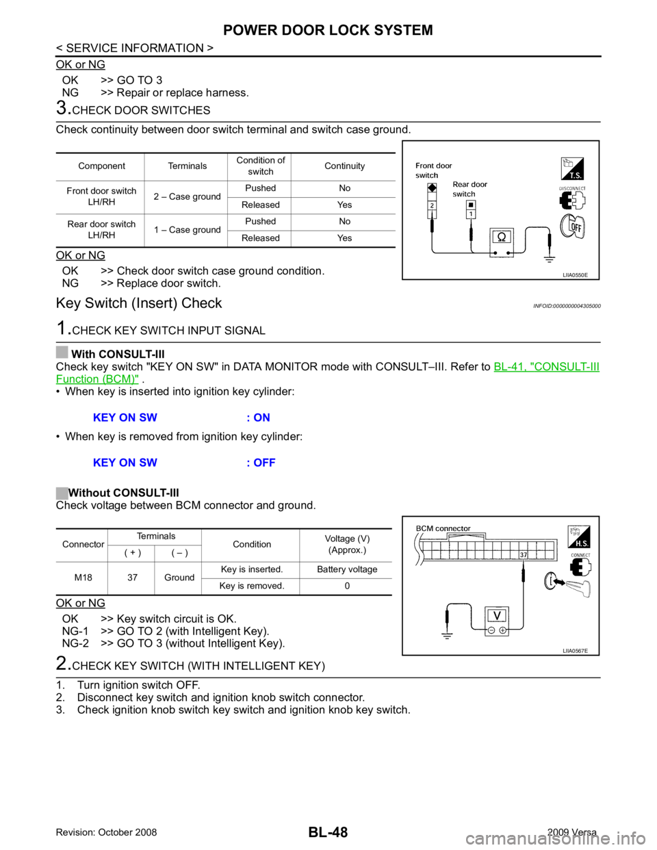
OK >> GO TO 3
NG >> Repair or replace harness. OK >> Check door switch case ground condition.
NG >> Replace door switch.
Key Switch (I nsert) Check INFOID:0000000004305000 CONSULT-III
Function (BCM) " .
• When key is inserted into ignition key cylinder:
• When key is removed from ignition key cylinder:
Without CONSULT-III
Check voltage between BCM connector and ground.
OK or NG OK >> Key switch circuit is OK.
NG-1 >> GO TO 2 (with Intelligent Key).
NG-2 >> GO TO 3 (without Intelligent Key).
Page 512 of 4331
BL
N
O P
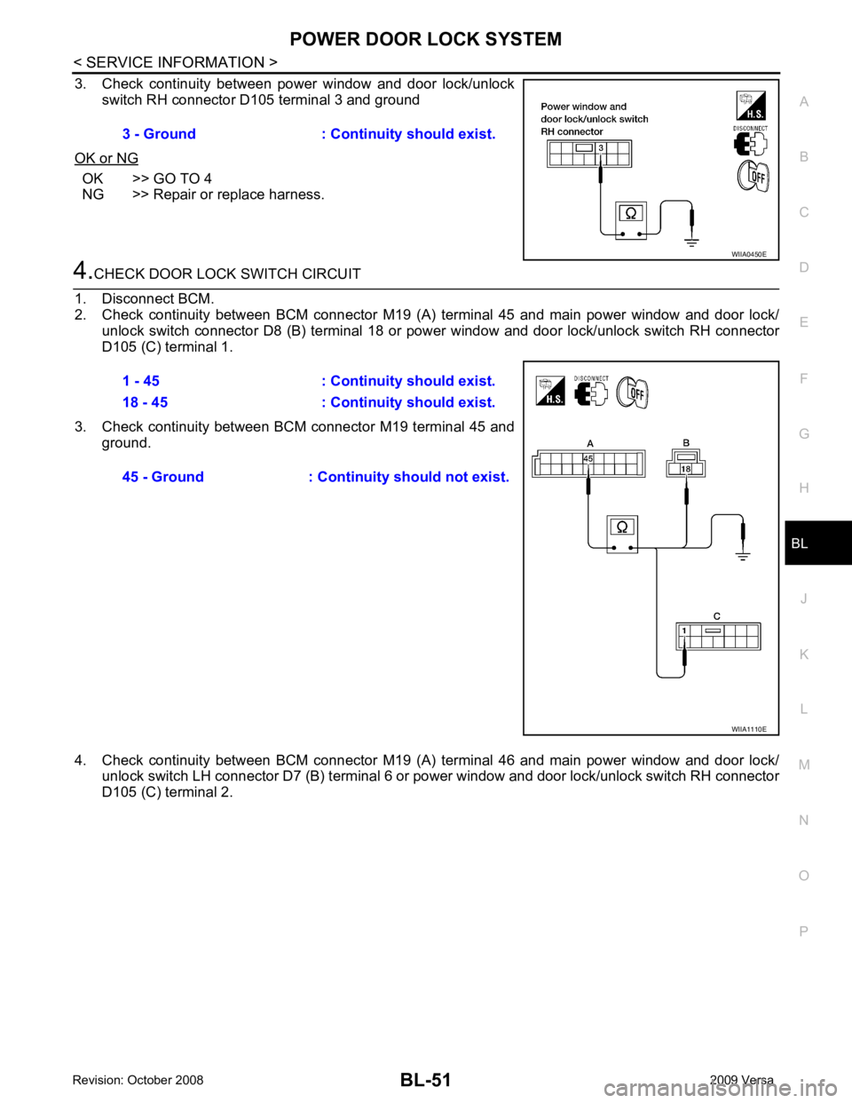
3. Check continuity between power window and door lock/unlock
switch RH connector D105 terminal 3 and ground
OK or NG OK >> GO TO 4
NG >> Repair or replace harness.
Page 514 of 4331
BL
N
O P
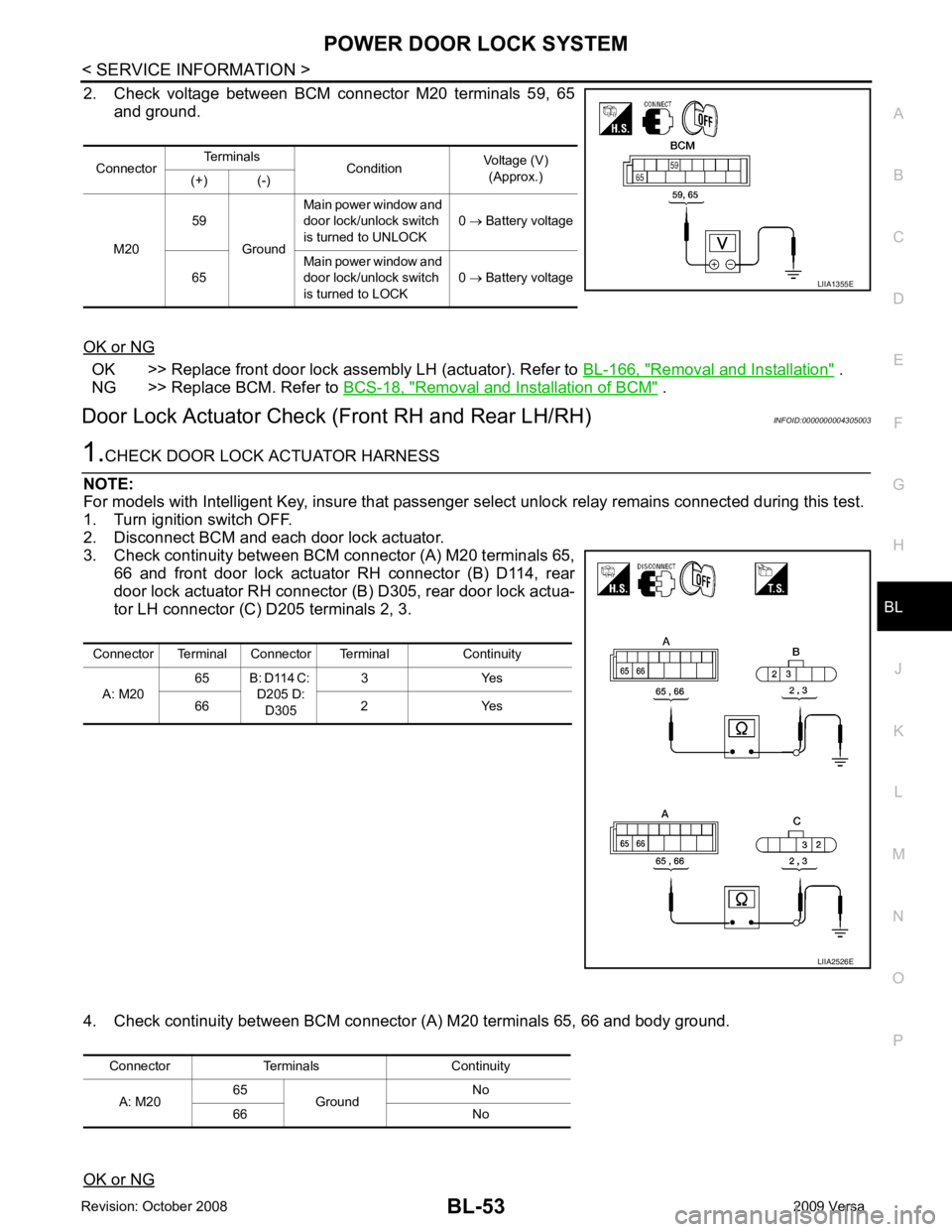
2. Check voltage between BCM connector M20 terminals 59, 65
and ground.
OK or NG OK >> Replace front door lock assembly LH (actuator). Refer to
BL-166, " Removal and Installation " .
NG >> Replace BCM. Refer to BCS-18, " Removal and Installation of BCM " .
Door Lock Actuator Check (Front RH and Rear LH/RH) INFOID:0000000004305003