belt NISSAN LATIO 2009 Service Service Manual
[x] Cancel search | Manufacturer: NISSAN, Model Year: 2009, Model line: LATIO, Model: NISSAN LATIO 2009Pages: 4331, PDF Size: 58.04 MB
Page 1177 of 4331
CVT
N
O P
CAUTION:
Touch “CLEAR” after changing CVT fluid, and then erase “CVTF DETERIORATION DATE”.
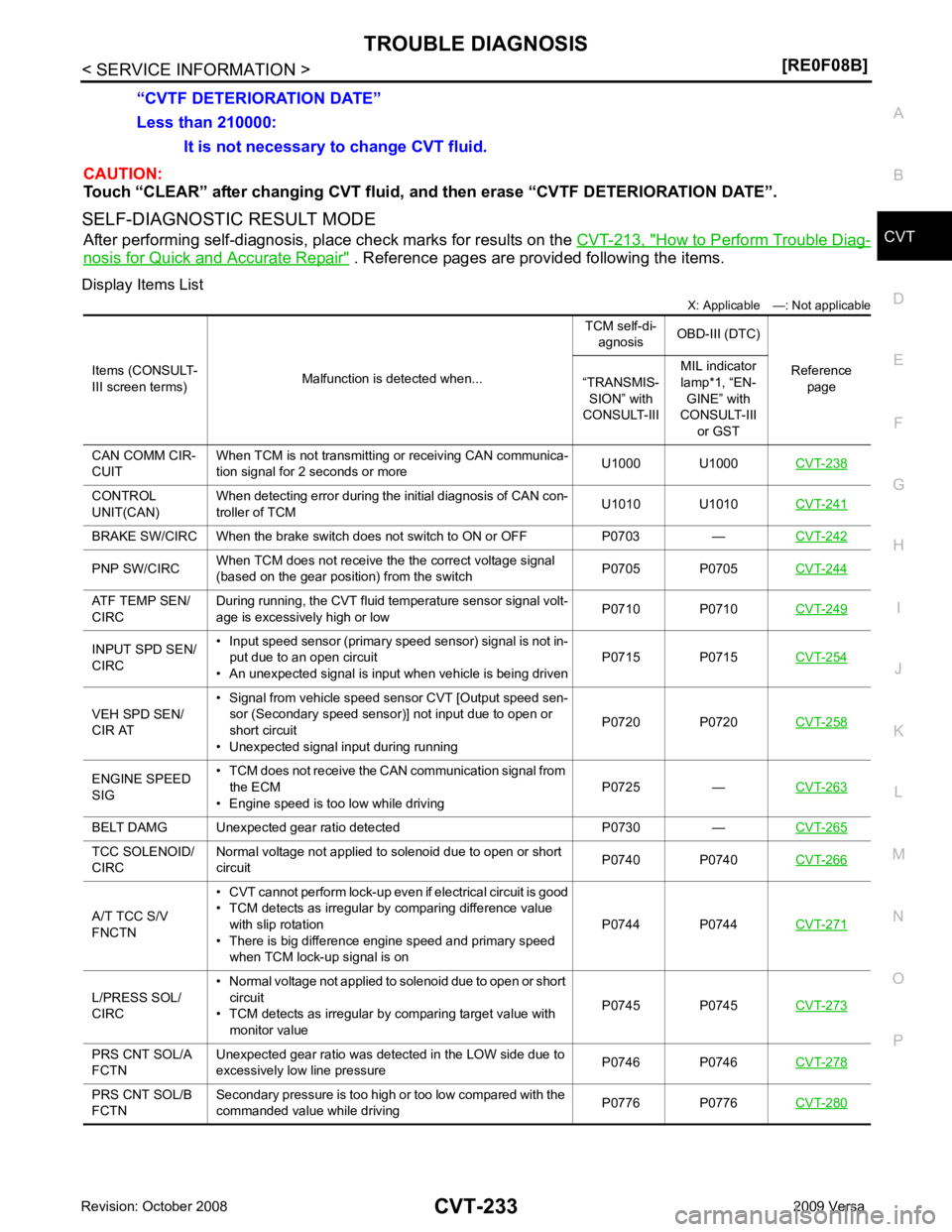
SELF-DIAGNOSTIC RESULT MODE After performing self-diagnosis, place check marks for results on the CVT-213, " How to Perform Trouble Diag-
nosis for Quick and Accurate Repair " . Reference pages are provided following the items.
Display Items List X: Applicable —: Not applicable
Less than 210000:
It is not necessary to change CVT fluid.
“CVTF DETERIORATION DATE”
Items (CONSULT-
III screen terms) Malfunction is detected when... TCM self-di-
agnosis OBD-III (DTC)
Reference page
“TRANSMIS-
SION” with
CONSULT-III MIL indicator
lamp*1, “EN- GINE” with
CONSULT-III
or GST
CAN COMM CIR-
CUIT When TCM is not transmitting or receiving CAN communica-
tion signal for 2 seconds or more U1000 U1000
CVT-238CONTROL
UNIT(CAN) When detecting error during the initial diagnosis of CAN con-
troller of TCM U1010 U1010
CVT-241BRAKE SW/CIRC When the brake switch does not switch to ON or OFF P0703 —
CVT-242PNP SW/CIRC
When TCM does not receive the the correct voltage signal
(based on the gear position) from the switch P0705 P0705
CVT-244ATF TEMP SEN/
CIRC During running, the CVT fluid temperature sensor signal volt-
age is excessively high or low P0710 P0710
CVT-249INPUT SPD SEN/
CIRC • Input speed sensor (primary speed sensor) signal is not in-
put due to an open circuit
• An unexpected signal is input when vehicle is being driven P0715 P0715
CVT-254VEH SPD SEN/
CIR AT • Signal from vehicle speed sensor CVT [Output speed sen-
sor (Secondary speed sensor)] not input due to open or
short circuit
• Unexpected signal input during running P0720 P0720
CVT-258ENGINE SPEED
SIG • TCM does not receive the CAN communication signal from
the ECM
• Engine speed is too low while driving P0725 —
CVT-263BELT DAMG Unexpected gear ratio detected P0730 —
CVT-265TCC SOLENOID/
CIRC Normal voltage not applied to solenoid due to open or short
circuit P0740 P0740
CVT-266A/T TCC S/V
FNCTN • CVT cannot perform lock-up even if electrical circuit is good
• TCM detects as irregular by comparing difference value with slip rotation
• There is big difference engine speed and primary speed
when TCM lock-up signal is on P0744 P0744
CVT-271L/PRESS SOL/
CIRC • Normal voltage not applied to solenoid due to open or short
circuit
• TCM detects as irregular by comparing target value with
monitor value P0745 P0745
CVT-273PRS CNT SOL/A
FCTN Unexpected gear ratio was detected in the LOW side due to
excessively low line pressure P0746 P0746
CVT-278PRS CNT SOL/B
FCTN Secondary pressure is too high or too low compared with the
commanded value while driving P0776 P0776
CVT-280
Page 1209 of 4331
CVT
N
O P
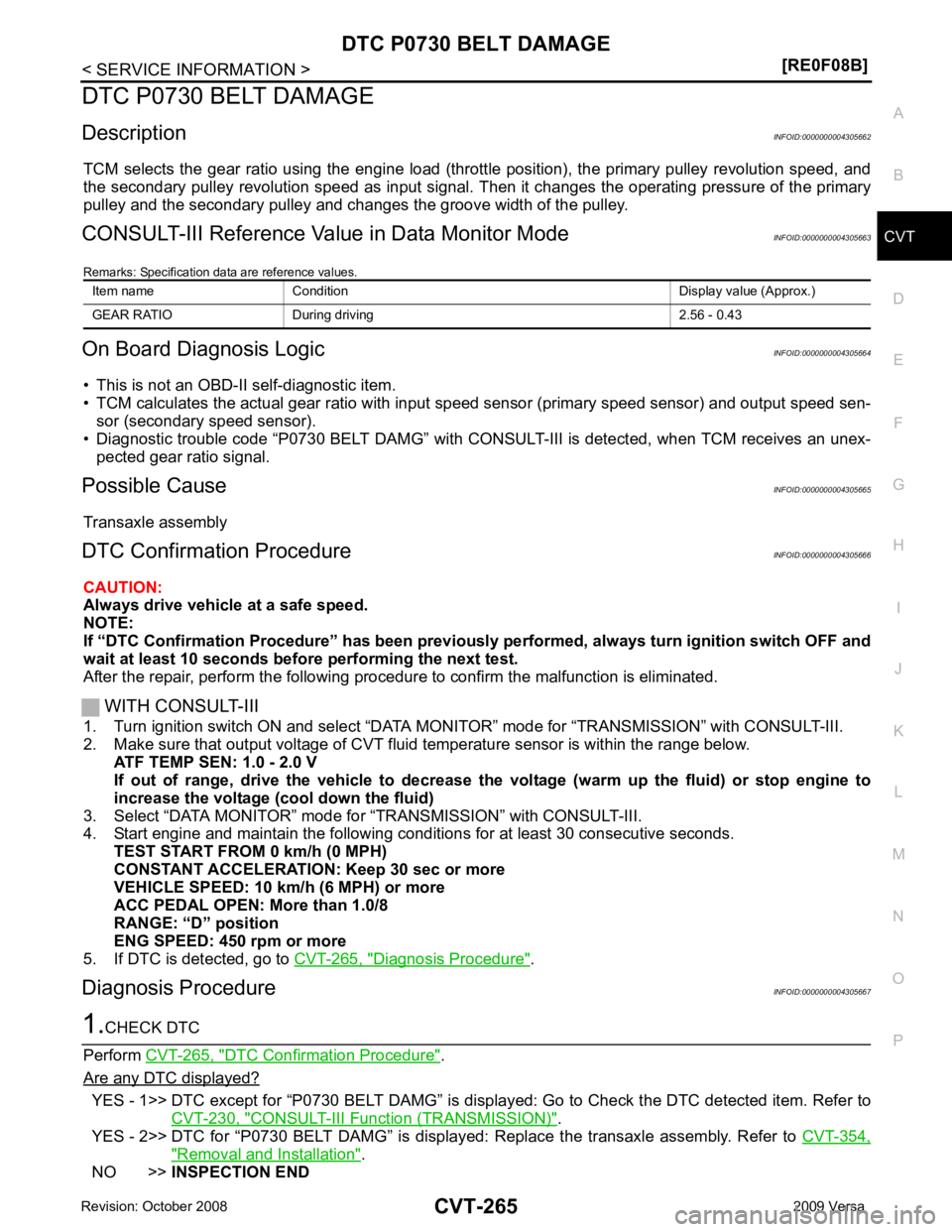
DTC P0730 BELT DAMAGE
Description INFOID:0000000004305662
TCM selects the gear ratio using the engine load (throttle position), the primary pulley revolution speed, and
the secondary pulley revolution speed as input signal. T hen it changes the operating pressure of the primary
pulley and the secondary pulley and changes the groove width of the pulley.
CONSULT-III Reference Val ue in Data Monitor Mode INFOID:0000000004305663
Remarks: Specification data are reference values.
On Board Diagnosis Logic INFOID:0000000004305664
• This is not an OBD-II self-diagnostic item.
• TCM calculates the actual gear ratio with input speed sensor (primary speed sensor) and output speed sen-
sor (secondary speed sensor).
• Diagnostic trouble code “P0730 BELT DAMG” with CONSUL T-III is detected, when TCM receives an unex-
pected gear ratio signal.
Possible Cause INFOID:0000000004305665
Transaxle assembly
DTC Confirmation Procedure INFOID:0000000004305666
CAUTION:
Always drive vehicle at a safe speed.
NOTE:
If “DTC Confirmation Procedure” has been previously performed, alw ays turn ignition switch OFF and
wait at least 10 seconds before performing the next test.
After the repair, perform the following procedure to confirm the malfunction is eliminated.
WITH CONSULT-III
1. Turn ignition switch ON and select “DATA MO NITOR” mode for “TRANSMISSION” with CONSULT-III.
2. Make sure that output voltage of CVT fluid temperature sensor is within the range below.
ATF TEMP SEN: 1.0 - 2.0 V
If out of range, drive the vehicle to decrease the voltage (warm up the fluid) or stop engine to
increase the voltage (c ool down the fluid)
3. Select “DATA MONITOR” mode for “TRANSMISSION” with CONSULT-III.
4. Start engine and maintain the following conditions for at least 30 consecutive seconds.
TEST START FROM 0 km/h (0 MPH)
CONSTANT ACCELERATION: Keep 30 sec or more
VEHICLE SPEED: 10 km/h (6 MPH) or more
ACC PEDAL OPEN: More than 1.0/8
RANGE: “D” position
ENG SPEED: 450 rpm or more
5. If DTC is detected, go to CVT-265, " Diagnosis Procedure " .
Diagnosis Procedure INFOID:0000000004305667DTC Confirmation Procedure " .
Are any DTC displayed? YES - 1>> DTC except for “P0730 BELT DAMG” is displa
yed: Go to Check the DTC detected item. Refer to
CVT-230, " CONSULT-III Function (TRANSMISSION) " .
YES - 2>> DTC for “P0730 BELT DAMG” is displayed: Replace the transaxle assembly. Refer to CVT-354," Removal and Installation " .
NO >> INSPECTION END
Item name Condition Display value (Approx.)
GEAR RATIO During driving 2.56 - 0.43
Page 1303 of 4331

DI
N
O P
CONTENTS
DRIVER INFORMATION SYSTEM
SERVICE INFORMATION .. ..........................2
PRECAUTION ................................................ .....2
Precaution for Supplemental Restraint System
(SRS) "AIR BAG" and "SEAT BELT PRE-TEN-
SIONER" ............................................................. ......
2
COMBINATION METERS .............................. .....3
Component Parts and Harness Connector Loca-
tion ...................................................................... ......
3
System Description ............................................. ......3
Arrangement of Combination Meter .................... ......5
Internal Circuit ..................................................... ......6
Wiring Diagram - METER - ................................. ......7
Combination Meter Harness Connector Terminal
Layout ................................................................. ......
9
Terminal and Reference Value for Combination
Meter ................................................................... ......
9
Self-Diagnosis Mode of Combination Meter ........ ....10
CONSULT-III Function (METER/M&A) ............... ....12
Trouble Diagnosis ............................................... ....13
Symptom Chart ................................................... ....14
Power Supply and Ground Circuit Inspection ..... ....14
Vehicle Speed Signal Inspection ......................... ....15
Engine Speed Signal Inspection ......................... ....16
Fuel Level Sensor Signal Inspection ................... ....16
Fuel Gauge Fluctuates, Indicates Wrong Value, or
Varies .................................................................. ....
18
Fuel Gauge Does Not Move to Full-position ...........18
DTC [U1000] CAN Communication Circuit ......... ....18
Electrical Component Inspection ......................... ....19
Removal and Installation .........................................19
WARNING LAMPS ......................................... ....20
Schematic ........................................................... ....20
Wiring Diagram - WARN - ................................... ....21 Oil Pressure Wa
rning Lamp Stays Off (Ignition
Switch ON) .......................................................... ....
29
Oil Pressure Wa rning Lamp Does Not Turn Off
(Oil Pressure Is Normal) ...................................... ....
31
Component Inspection ......................................... ....31
A/T INDICATOR ................................................ 33
System Description .............................................. ....33
Wiring Diagram - AT/IND - ................................... ....34
A/T Indicator Does Not Illuminate ........................ ....35
CVT INDICATOR ............................................... 37
System Description .............................................. ....37
Schematic ............................................................ ....37
Wiring Diagram - CVTIND - ................................. ....38
CVT Indicator Does Not Illuminate ...................... ....40
WARNING CHIME ............................................. 42
Component Parts and Harness Connector Loca-
tion ....................................................................... ....
42
System Description .............................................. ....42
Wiring Diagram - CHIME - ................................... ....45
Terminal and Reference Value for BCM ..................46
CONSULT-III Function (B CM) .................................46
Trouble Diagnosis ................................................ ....47
Combination Meter Buzzer Cir cuit Inspection .........48
Front Door Switch LH Signal Inspection .............. ....49
Key Switch Signal Inspec tion (Without Intelligent
Key) ..................................................................... ....
50
Key Switch and Ignition Knob Switch Signal In-
spection (With Intelligent Key, When Mechanical
Key Is Used) ........................................................ ....
51
Lighting Switch Signal Inspection ........................ ....53
Parking Brake Switch Signal Inspection .............. ....53
Electrical Component Inspection ......................... ....54
Page 1311 of 4331
DI
N
O P
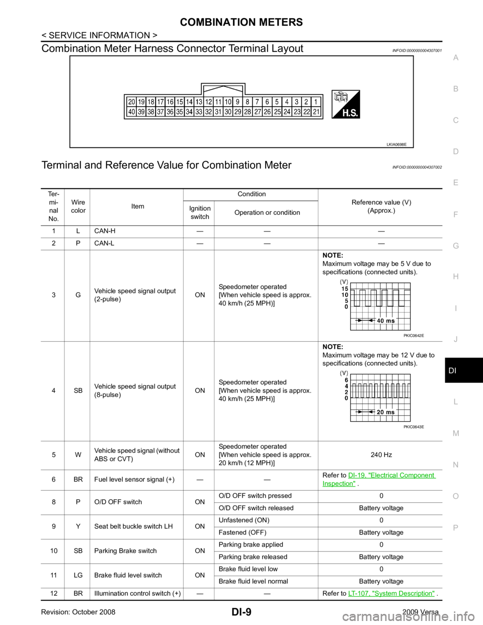
Combination Meter Harness Connector Terminal Layout
INFOID:0000000004307001
Terminal and Reference Va lue for Combination Meter INFOID:0000000004307002 Electrical Component
Inspection " .
8 P O/D OFF switch ON O/D OFF switch pressed 0
O/D OFF switch released Battery voltage
9 Y Seat belt buckle switch LH ON Unfastened (ON) 0
Fastened (OFF) Battery voltage
10 SB Parking Brake switch ON Parking brake applied 0
Parking brake released Battery voltage
11 LG Brake fluid level switch ON Brake fluid level low 0
Brake fluid level normal Battery voltage
12 BR Illumination control switch (+) — — Refer to LT-107, " System Description " .
Page 1312 of 4331
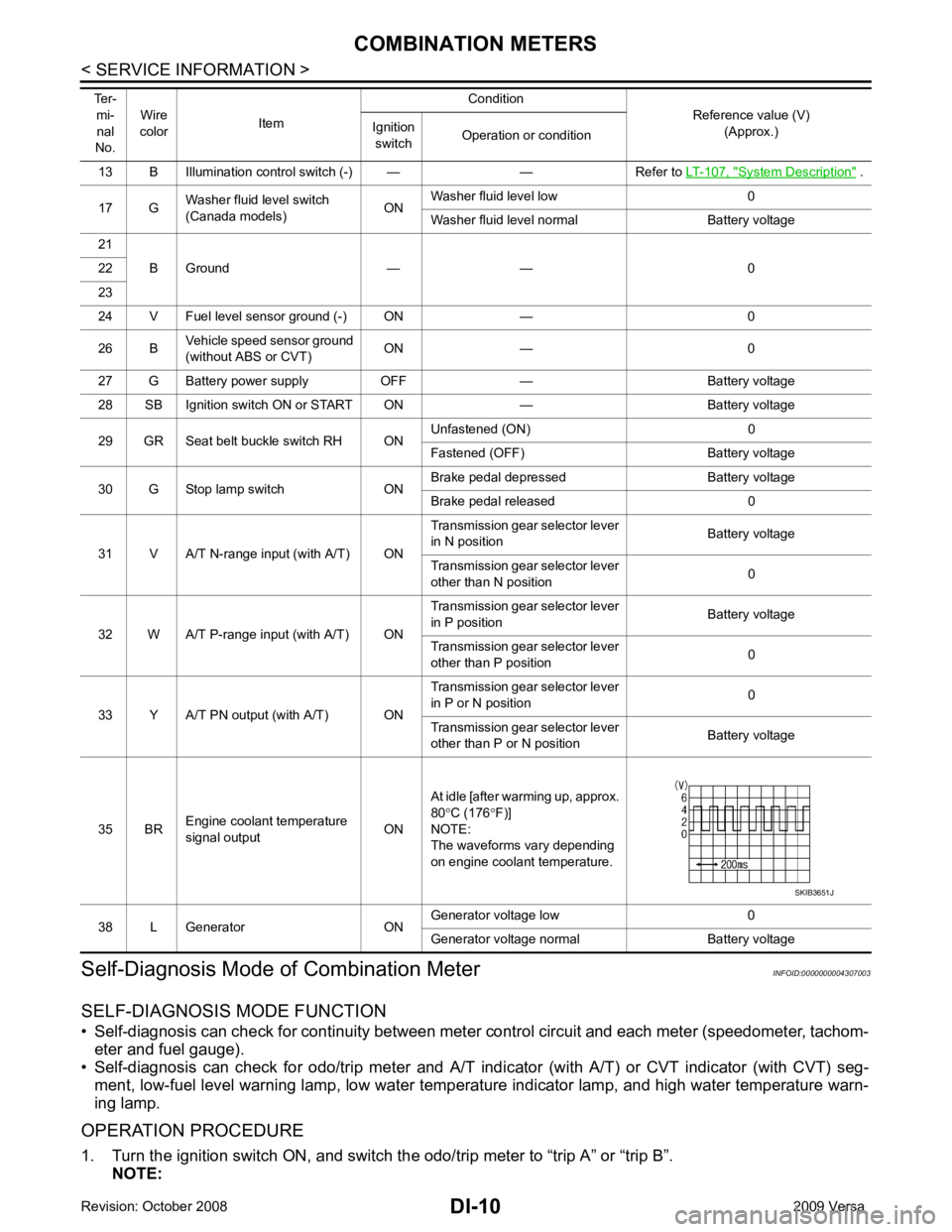
System Description " .
17 G Washer fluid level switch
(Canada models) ONWasher fluid level low 0
Washer fluid level normal Battery voltage
21 B Ground — — 0
22
23
24 V Fuel level sensor ground (-) ON — 0
26 B Vehicle speed sensor ground
(without ABS or CVT) ON — 0
27 G Battery power supply OFF — Battery voltage
28 SB Ignition switch ON or START ON — Battery voltage
29 GR Seat belt buckle switch RH ON Unfastened (ON) 0
Fastened (OFF) Battery voltage
30 G Stop lamp switch ON Brake pedal depressed Battery voltage
Brake pedal released 0
31 V A/T N-range input (with A/T) ON Transmission gear selector lever
in N position Battery voltage
Transmission gear selector lever
other than N position 0
32 W A/T P-range input (with A/T) ON Transmission gear selector lever
in P position Battery voltage
Transmission gear selector lever
other than P position 0
33 Y A/T PN output (with A/T) ON Transmission gear selector lever
in P or N position 0
Transmission gear selector lever
other than P or N position Battery voltage
35 BR Engine coolant temperature
signal output ONAt idle [after warming up, approx.
80 °C (176 °F)]
NOTE:
The waveforms vary depending
on engine coolant temperature.
38 L Generator ON Generator voltage low 0
Generator voltage normal Battery voltage
Ter-
mi-
nal
No. Wire
color Item Condition
Reference value (V)
(Approx.)
Ignition
switch Operation or condition
Page 1314 of 4331
![NISSAN LATIO 2009 Service Service Manual CONSULT-III display Malfunction Reference page
CAN COMM CIRC [U1000] Malfunction is detected in CAN communication lines.
CAUTION:
Even when there is no malfunct ion on CAN communication system, mal-
f](/img/5/57359/w960_57359-1313.png "NISSAN LATIO 2009 Service Service Manual CONSULT-III display Malfunction Reference page
CAN COMM CIRC [U1000] Malfunction is detected in CAN communication lines.
CAUTION:
Even when there is no malfunct ion on CAN communication system, mal-
f")
CONSULT-III display Malfunction Reference page
CAN COMM CIRC [U1000] Malfunction is detected in CAN communication lines.
CAUTION:
Even when there is no malfunct ion on CAN communication system, mal-
function may be misinterpreted when battery has low voltage (when main-
taining 7 - 8 V for about 2 seconds) or 10A fuse [No. 14, located in the fuse
block (J/B)] is removed. DI-18VEHICLE SPEED CIRC [B2205]
Malfunction is detected when an erroneous speed signal is input.
CAUTION:
Even when there is no malfunction on speed signal system, malfunctions
may be misinterpreted when battery has low voltage (when maintaining 7
- 8 V for about 2 seconds). DI-15Display item [Unit]
MAIN
SIGNALS SELECTION
FROM MENU Contents
SPEED METER [km/h] X X The value of vehicle speed sign
al, which is input from ABS ac-
tuator and electric unit (control unit).
SPEED OUTPUT [km/h] X X The value of vehicle speed signal, which is transmitted to each
unit with CAN communication.
TACHO METER [rpm] X X The value of engine speed signal, which is input from ECM.
W TEMP METER [ °C] X X The value of engine coolant temperature signal, which is input
from ECM.
FUEL METER [lit.] X X The value, which processes a resistance signal from fuel
gauge.
DISTANCE [km] X X The value, which is calculated by vehicle speed signal from
ABS actuator and electric unit (con trol unit), fuel gauge and fuel
consumption signal from ECM.
FUEL W/L [ON/OFF] X X Indicates [ON/OFF] condition of low-fuel warning lamp.
C-ENG W/L [ON/OFF] X Indicates [ON/OFF] condition of malfunction indicator lamp
(MIL).
AIR PRES W/L X Indicates [ON/OFF] condition of low tire pressure warning lamp.
SEAT BELT W/L X Indicates [ON/OFF] condition of seat belt warning lamp.
BUZZER [ON/OFF] X X Indicates [ON/ OFF] condition of buzzer.
DOOR W/L [ON/OFF] X Indicates [ON/OFF] condition of door warning lamp.
HI-BEAM IND [ON/OFF] X Indicat es [ON/OFF] condition of high beam indicator lamp.
Page 1349 of 4331
![NISSAN LATIO 2009 Service Service Manual DI
N
O P
DATA MONITOR
Display Item List
ACTIVE TEST
Display Item List
SELF-DIAG RESULTS
Display Item List
NOTE:
If “CAN communication [U1000]” is indicated, after prin ting the monitor i](/img/5/57359/w960_57359-1348.png "NISSAN LATIO 2009 Service Service Manual DI
N
O P
DATA MONITOR
Display Item List
ACTIVE TEST
Display Item List
SELF-DIAG RESULTS
Display Item List
NOTE:
If “CAN communication [U1000]” is indicated, after prin ting the monitor i")
DI
N
O P
DATA MONITOR
Display Item List
ACTIVE TEST
Display Item List
SELF-DIAG RESULTS
Display Item List
NOTE:
If “CAN communication [U1000]” is indicated, after prin ting the monitor item, go to “LAN system”. Refer to
LAN-17, " Trouble Diagnosis Flow Chart " .
Trouble Diagnosis INFOID:0000000004307032
HOW TO PERFORM TROUBLE DIAGNOSIS 1. Confirm the symptom and customer complaint.
2. Understand the outline of system. Refer to DI-42, " System Description " .
3. Perform the preliminary inspection. Refer to "PRELIMINARY INSPECTION".
4. According to symptom c hart, repair or replace the cause of the malfunction. Refer to "SYMPTOM
CHART".
5. Does warning chime system operate normally? If it operates normally, GO TO 6. If not, GO TO 4.
6. Inspection End.
PRELIMINARY INSPECTION BCM diagnostic
test item Diagnostic mode Description
Inspection by part WORK SUPPORT
Supports inspections and adjustments. Commands are transmitted to the BCM for
setting the status suitable for required operation, input/output signals are received
from the BCM and received data is displayed.
DATA MONITOR Displays BCM input/output data in real time. ACTIVE TEST Operation of electrical loads can be checked by sending drive signal to them.
SELF-DIAG RESULTS Displays BCM self-diagnosis results.
CAN DIAG SUPPORT MNTR The result of transmit/receive diagnosis of CAN communication can be read. ECU PART NUMBER BCM part number can be read.CONFIGURATION Performs BCM configuration read/write functions. Monitored item ALL SIGNALS
SELECTION
FROM MENU Contents
IGN ON SW X X Indicates [ON/OFF] condition of ignition switch.
KEY ON SW X X Indicates [ON/OFF] condition of key switch.
DOOR SW-DR X X Indicates [ON/OFF] condition of front door switch LH.
LIGHT SW 1ST X X Indicates [ON/OFF] condition of lighting switch.
BUCKLE SW X X Indicates [ON/OFF] condition of seat belt buckle switch LH. Test item Malfunction is detected when···
IGN KEY WARN ALM This test is able to check key warning chime operation.
LIGHT WARN ALM This test is able to check light warning chime operation.
SEAT BELT WARN TEST This test is able to check seat belt warning chime operation. Display item [Code] Malfunction is detected when...
CAN communication [U1000] Malfunction is detected in CAN communication.
Page 1363 of 4331

EC
A
N
O P
Inspection ............................................................
..
500
ON-VEHICLE REPAIR .... ...........................502
EVAP CANISTER ........................................... ..502
Exploded View .................................................... ..502
Removal and Installation .......................................502
Inspection ............................................................ ..503
SERVICE DATA AND SPECIFICATIONS
(SDS) ......... ................................. ................504
SERVICE DATA AND SPECIFICATIONS
(SDS) .............................................................. ..504
Idle Speed ........................................................... ..504
Ignition Timing ..................................................... ..504
Calculated Load Value ........................................ ..504
Mass Air Flow Sensor ......................................... ..504
MR TYPE 1
SERVICE INFOMATION .. ..........................505
APPLICATION NOTICE ................................. ..505
How to Check Vehicle Type ................................ ..505
INDEX FOR DTC ............................................ ..506
U1000-U1010 ...................................................... ..506
P0011-P0075 ...................................................... ..506
P0101-P0128 ...................................................... ..506
P0130-P0183 ...................................................... ..507
P0222-P0420 ...................................................... ..507
P0441-P0463 ...................................................... ..508
P0500-P0643 ...................................................... ..508
P0705-P0734 ...................................................... ..508
P0740-P0845 ...................................................... ..509
P0850-P1574 ...................................................... ..509
P1610-P1615 ...................................................... ..510
P1705-P1805 ...................................................... ..510
P2100-P2A00 ...................................................... ..510
PRECAUTIONS .............................................. ..512
Precaution for Supplemental Restraint System
(SRS) "AIR BAG" and "SEAT BELT PRE-TEN-
SIONER" ............................................................. ..
512
Precaution for Procedure without Cowl Top Cover ..512
On Board Diagnosis (OBD) System of Engine and
A/T, CVT ............................................................. ..
512
Precaution ........................................................... ..513
PREPARATION .............................................. ..516
Special Service Tool ........................................... ..516
Commercial Service Tool .................................... ..516
ENGINE CONTROL SYSTEM ........................ ..518
Schematic ........................................................... ..518
Multiport Fuel Injection (MFI) System ................. ..518
Electronic Ignition (EI) System ............................ ..521
Fuel Cut Control (at No Load and High Engine
Speed) ................................................................. ..
521
AIR CONDITIONING CUT CONTROL ........... ..523 Input/Output Signal Chart ....................................
..523
System Description .............................................. ..523
AUTOMATIC SPEED CONTROL DEVICE
(ASCD) ............................................................ 524
System Description .............................................. ..524
Component Description ....................................... ..525
CAN COMMUNICATION ................................. 526
System Description .............................................. ..526
EVAPORATIVE EMISSION SYSTEM ............. 527
Description ........................................................... ..527
Component Inspection ......................................... ..529
Removal and Installation ..................................... ..531
How to Detect Fuel Vapor Leakage ..................... ..531
ON BOARD REFUELING VAPOR RECOV-
ERY (ORVR) .................................................... 533
System Description .............................................. ..533
Diagnosis Procedure ........................................... ..533
Component Inspection ......................................... ..535
POSITIVE CRANKCASE VENTILATION ....... 538
Description ........................................................... ..538
Component Inspection ......................................... ..538
NVIS (NISSAN VEHICLE IMMOBILIZER SYS-
TEM-NATS) ..................................................... 540
Description ........................................................... ..540
ON BOARD DIAGNOSTIC (OBD) SYSTEM .. 541
Introduction .......................................................... ..541
Two Trip Detection Logic ..................................... ..541
Emission-related Diagnostic Information ............. ..542
Malfunction Indicator Lamp (MIL) ..........................557
OBD System Operation Chart ............................. ..560
BASIC SERVICE PROCEDURE ..................... 566
Basic Inspection .................................................. ..566
Idle Speed and Ignition Timing Check ................. ..570
Procedure After Replacing ECM ......................... ..571
VIN Registration .................................................. ..572
Accelerator Pedal Released Position Learning ... ..572
Throttle Valve Closed Position Learning ............. ..572
Idle Air Volume Learning ..................................... ..572
Fuel Pressure Check ........................................... ..574
TROUBLE DIAGNOSIS .................................. 577
Trouble Diagnosis Introduction ............................ ..577
DTC Inspection Priority Chart .............................. ..581
Fail-Safe Chart .................................................... ..582
Symptom Matrix Chart ......................................... ..583
Engine Control Component Parts Location ......... ..588
Vacuum Hose Drawing ........................................ ..594
Circuit Diagram .................................................... ..595
ECM Harness Connector Terminal Layout .......... ..597
ECM Terminal and Reference Value ................... ..597
CONSULT-III Function (ENGINE) ....................... ..604
Generic Scan Tool (GST) Function ..................... ..612
Page 1848 of 4331
![NISSAN LATIO 2009 Service Service Manual EC-492< PRECAUTION >
[HR16DE]
PRECAUTIONS
PRECAUTION
PRECAUTIONS
Precaution for Supplemental Restraint Syst em (SRS) "AIR BAG" and "SEAT BELT
PRE-TENSIONER" INFOID:0000000004786987
The Supplemental](/img/5/57359/w960_57359-1847.png "NISSAN LATIO 2009 Service Service Manual EC-492< PRECAUTION >
[HR16DE]
PRECAUTIONS
PRECAUTION
PRECAUTIONS
Precaution for Supplemental Restraint Syst em (SRS) \"AIR BAG\" and \"SEAT BELT
PRE-TENSIONER\" INFOID:0000000004786987
The Supplemental")
EC-492< PRECAUTION >
[HR16DE]
PRECAUTIONS
PRECAUTION
PRECAUTIONS
Precaution for Supplemental Restraint Syst em (SRS) "AIR BAG" and "SEAT BELT
PRE-TENSIONER" INFOID:0000000004786987
The Supplemental Restraint System such as “A IR BAG” and “SEAT BELT PRE-TENSIONER”, used along
with a front seat belt, helps to reduce the risk or severi ty of injury to the driver and front passenger for certain
types of collision. This system includes seat belt switch inputs and dual stage front air bag modules. The SRS
system uses the seat belt switches to determine the front air bag deployment, and may only deploy one front
air bag, depending on the severity of a collision and w hether the front occupants are belted or unbelted.
Information necessary to service the system safely is included in the “SUPPLEMENTAL RESTRAINT SYS-
TEM” and “SEAT BELTS” of this Service Manual.
WARNING:
• To avoid rendering the SRS inopera tive, which could increase the risk of personal injury or death in
the event of a collision which would result in air bag inflation, all maintenance must be performed by
an authorized NISS AN/INFINITI dealer.
• Improper maintenance, including in correct removal and installation of the SRS, can lead to personal
injury caused by unintent ional activation of the system. For re moval of Spiral Cable and Air Bag
Module, see the “SUPPLEMEN TAL RESTRAINT SYSTEM”.
• Do not use electrical test equipmen t on any circuit related to the SRS unless instructed to in this
Service Manual. SRS wiring harn esses can be identified by yellow and/or orange harnesses or har-
ness connectors.
PRECAUTIONS WHEN USING POWER TOOLS (AIR OR ELECTRIC) AND HAMMERS
WARNING:
• When working near the Airbag Diagnosis Sensor Unit or other Airbag System sensors with the igni-
tion ON or engine running, DO NOT use air or electri c power tools or strike near the sensor(s) with a
hammer. Heavy vibration could activate the sensor( s) and deploy the air bag(s), possibly causing
serious injury.
• When using air or electric power tools or hammers , always switch the ignition OFF, disconnect the
battery, and wait at least 3 minu tes before performing any service.
Precaution for Procedure without Cowl Top Cover INFOID:0000000004786988
When performing the procedure after removing cowl top cover, cover
the lower end of windshield with urethane, etc.
On Board Diagnosis (OBD) S ystem of Engine and A/T INFOID:0000000004780394
The ECM has an on board diagnostic system. It will light up the malfunction indicator lamp (MIL) to warn the
driver of a malfunction causing emission deterioration.
CAUTION:
• Be sure to turn the ignition sw itch OFF and disconnect the negative battery cable before any repair
or inspection work. The open/short circuit of re lated switches, sensors, solenoid valves, etc. will
cause the MIL to light up.
• Be sure to connect and lock the connectors secure ly after work. A loose (unlocked) connector will
cause the MIL to light up due to the open circuit. (Be sure the connector is free from water, grease,
dirt, bent terminals, etc.)
• Certain systems and components, especially those related to OBD, may use a new style slide-lock-
ing type harness connector. For descrip tion and how to disconnect, refer to PG-64, " Description " .PIIB3706J
Page 1868 of 4331
![NISSAN LATIO 2009 Service Service Manual EC-512< SERVICE INFOMATION >
[MR TYPE 1]
PRECAUTIONS
PRECAUTIONS
Precaution for Supplemental Restraint Syst em (SRS) "AIR BAG" and "SEAT BELT
PRE-TENSIONER" INFOID:0000000004537013
The Supplemental](/img/5/57359/w960_57359-1867.png "NISSAN LATIO 2009 Service Service Manual EC-512< SERVICE INFOMATION >
[MR TYPE 1]
PRECAUTIONS
PRECAUTIONS
Precaution for Supplemental Restraint Syst em (SRS) \"AIR BAG\" and \"SEAT BELT
PRE-TENSIONER\" INFOID:0000000004537013
The Supplemental")
EC-512< SERVICE INFOMATION >
[MR TYPE 1]
PRECAUTIONS
PRECAUTIONS
Precaution for Supplemental Restraint Syst em (SRS) "AIR BAG" and "SEAT BELT
PRE-TENSIONER" INFOID:0000000004537013
The Supplemental Restraint System such as “A IR BAG” and “SEAT BELT PRE-TENSIONER”, used along
with a front seat belt, helps to reduce the risk or severi ty of injury to the driver and front passenger for certain
types of collision. This system includes seat belt switch inputs and dual stage front air bag modules. The SRS
system uses the seat belt switches to determine the front air bag deployment, and may only deploy one front
air bag, depending on the severity of a collision and w hether the front occupants are belted or unbelted.
Information necessary to service the system safely is included in the “SUPPLEMENTAL RESTRAINT SYS-
TEM” and “SEAT BELTS” of this Service Manual.
WARNING:
• To avoid rendering the SRS inopera tive, which could increase the risk of personal injury or death in
the event of a collision which would result in air bag inflation, all maintenance must be performed by
an authorized NISS AN/INFINITI dealer.
• Improper maintenance, including in correct removal and installation of the SRS, can lead to personal
injury caused by unintent ional activation of the system. For re moval of Spiral Cable and Air Bag
Module, see the “SUPPLEMEN TAL RESTRAINT SYSTEM”.
• Do not use electrical test equipmen t on any circuit related to the SRS unless instructed to in this
Service Manual. SRS wiring harn esses can be identified by yellow and/or orange harnesses or har-
ness connectors.
PRECAUTIONS WHEN USING POWER TOOLS (AIR OR ELECTRIC) AND HAMMERS
WARNING:
• When working near the Airbag Diagnosis Sensor Unit or other Airbag System sensors with the igni-
tion ON or engine running, DO NOT use air or electri c power tools or strike near the sensor(s) with a
hammer. Heavy vibration could activate the sensor( s) and deploy the air bag(s), possibly causing
serious injury.
• When using air or electric power tools or hammers , always switch the ignition OFF, disconnect the
battery, and wait at least 3 minu tes before performing any service.
Precaution for Procedure without Cowl Top Cover INFOID:0000000004537014
When performing the procedure after removing cowl top cover, cover
the lower end of windshield with urethane, etc.
On Board Diagnosis (OBD) Syst em of Engine and A/T, CVT INFOID:0000000004537015
The ECM has an on board diagnostic system. It will light up the malfunction indicator lamp (MIL) to warn the
driver of a malfunction causing emission deterioration.
CAUTION:
• Be sure to turn the ignition sw itch OFF and disconnect the battery ground cable before any repair or
inspection work. The open/short circuit of related sw itches, sensors, solenoid valves, etc. will cause
the MIL to light up.
• Be sure to connect and lock the connectors secure ly after work. A loose (unlocked) connector will
cause the MIL to light up due to the open circuit. (Be sure the connector is free from water, grease,
dirt, bent terminals, etc.)
• Certain systems and components, especially those related to OBD, may use a new style slide-lock-
ing type harness connector. For descrip tion and how to disconnect, refer to PG-64, " Description " .
• Be sure to route and secure the harnesses properly after work. The interference of the harness with
a bracket, etc. may cause the MIL to li ght up due to the short circuit. PIIB3706J