NISSAN LATIO 2009 Service Repair Manual
Manufacturer: NISSAN, Model Year: 2009, Model line: LATIO, Model: NISSAN LATIO 2009Pages: 4331, PDF Size: 58.04 MB
Page 831 of 4331
BR
N
O P
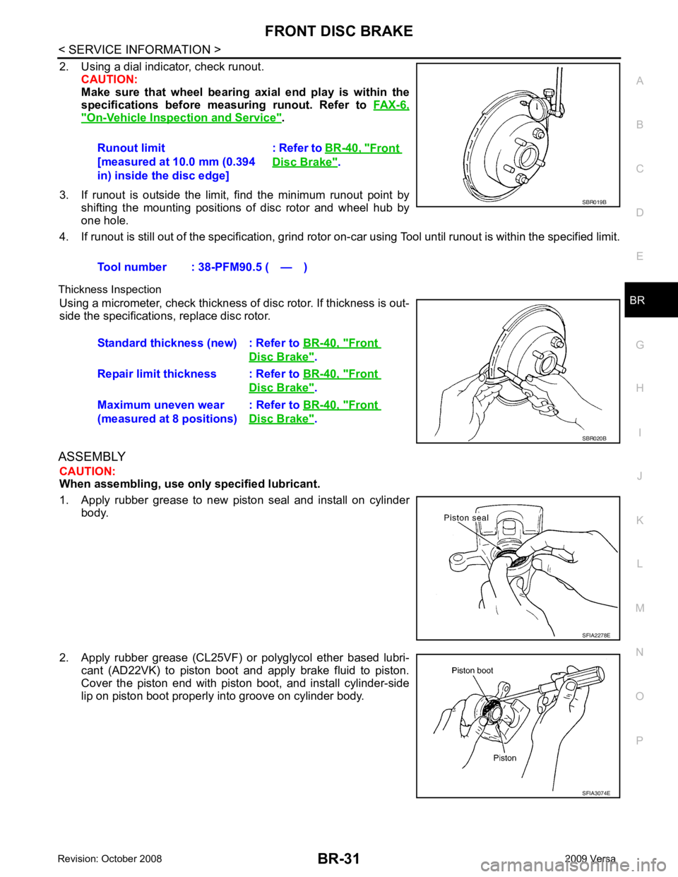
2. Using a dial indicator, check runout.
CAUTION:
Make sure that wheel bearing axi al end play is within the
specifications before measuring runout. Refer to FAX-6," On-Vehicle Inspection and Service " .
3. If runout is outside the limit, find the minimum runout point by shifting the mounting positions of disc rotor and wheel hub by
one hole.
4. If runout is still out of the specific ation, grind rotor on-car using Tool until runout is within the specified limit.
Thickness Inspection Using a micrometer, check thickness of disc rotor. If thickness is out-
side the specifications, replace disc rotor.
ASSEMBLY CAUTION:
When assembling, use only specified lubricant.
1. Apply rubber grease to new piston seal and install on cylinder body.
2. Apply rubber grease (CL25VF) or polyglycol ether based lubri- cant (AD22VK) to piston boot and apply brake fluid to piston.
Cover the piston end with piston boot, and install cylinder-side
lip on piston boot properly into groove on cylinder body. Runout limit
[measured at 10.0 mm (0.394
in) inside the disc edge] : Refer to
BR-40, " Front
Disc Brake " .
Tool number : 38-PFM90.5 ( — ) Front
Disc Brake " .
Repair limit thickness : Refer to BR-40, " Front
Disc Brake " .
Maximum uneven wear
(measured at 8 positions) : Refer to
BR-40, " Front
Disc Brake " .
Page 832 of 4331
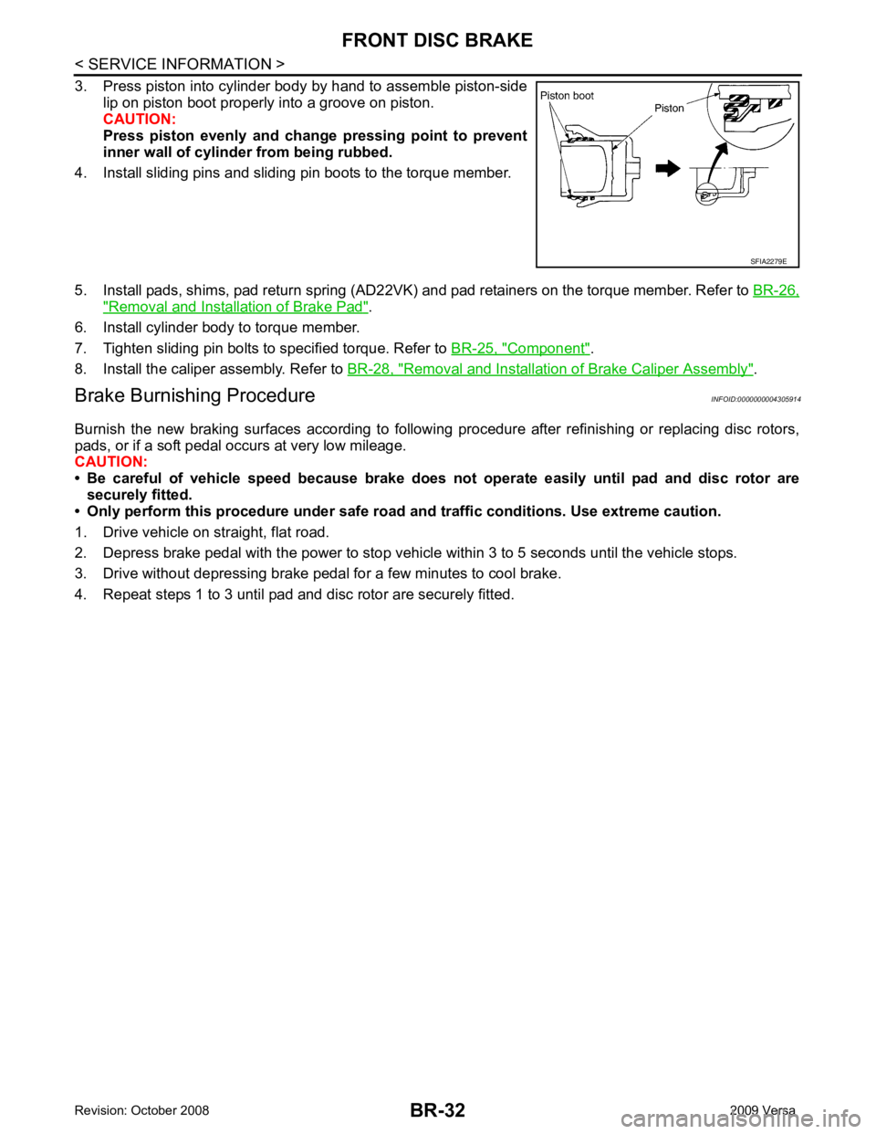
" Removal and Installation of Brake Pad " .
6. Install cylinder body to torque member.
7. Tighten sliding pin bolts to specified torque. Refer to BR-25, " Component " .
8. Install the caliper assembly. Refer to BR-28, " Removal and Installation of Brake Caliper Assembly " .
Brake Burnishing Procedure INFOID:0000000004305914
Burnish the new braking surfaces according to following procedure after refinishing or replacing disc rotors,
pads, or if a soft pedal occurs at very low mileage.
CAUTION:
• Be careful of vehicle speed because brake does not operate easily until pad and disc rotor are
securely fitted.
• Only perform this procedure under safe road and traffic conditions. Use extreme caution.
1. Drive vehicle on straight, flat road.
2. Depress brake pedal with the power to stop vehicl e within 3 to 5 seconds until the vehicle stops.
3. Drive without depressing brake pedal for a few minutes to cool brake.
4. Repeat steps 1 to 3 until pad and disc rotor are securely fitted.
Page 833 of 4331
BR
N
O P
REAR DRUM BRAKE
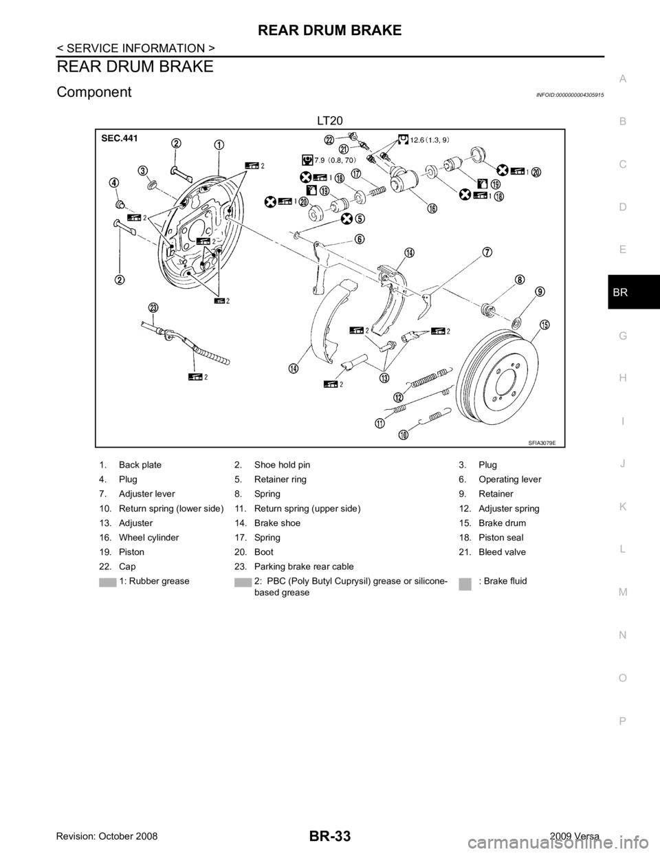
Component INFOID:0000000004305915
LT20
Page 834 of 4331
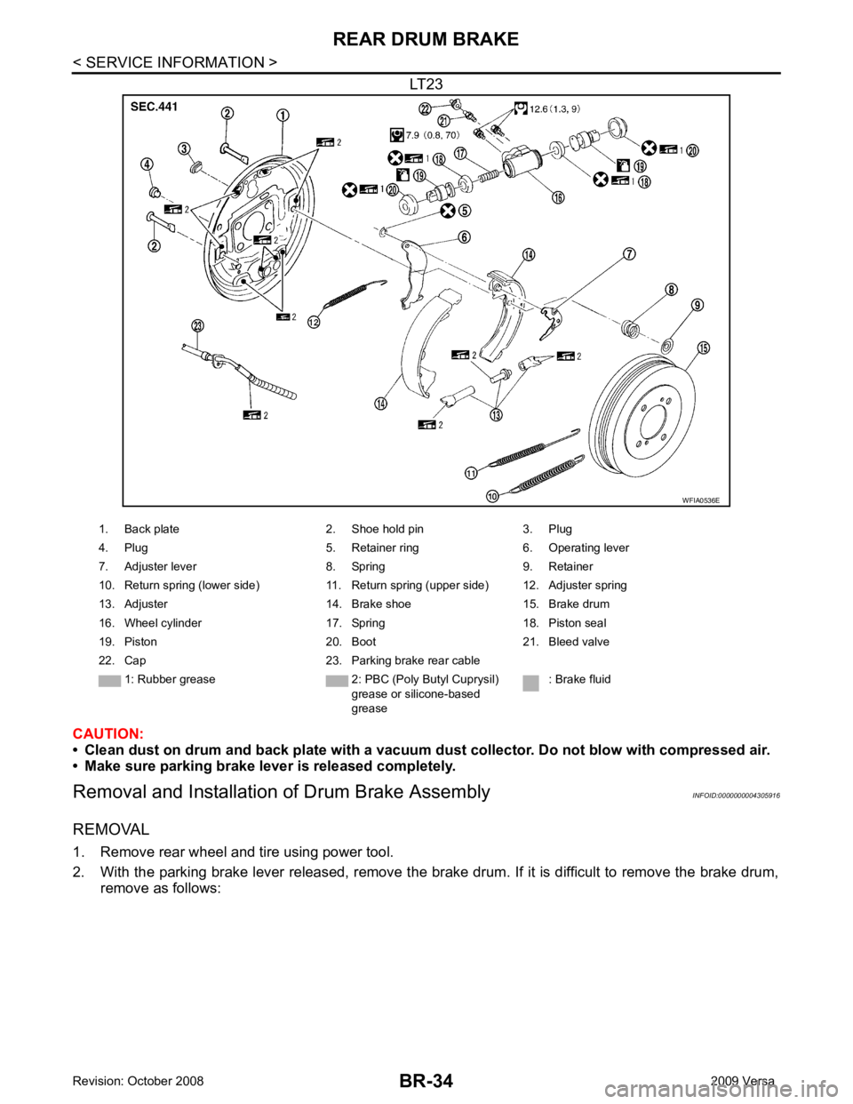
Page 835 of 4331
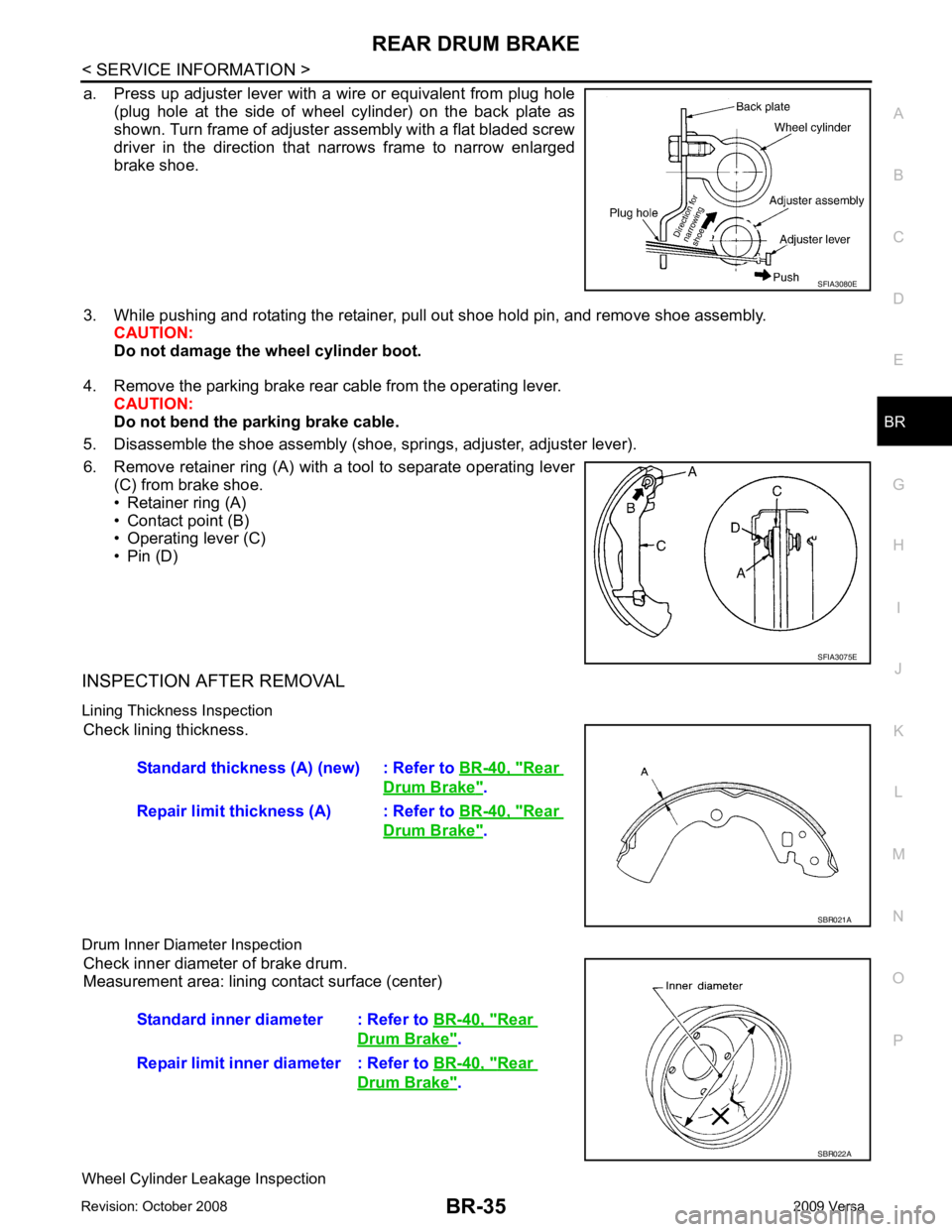
BR
N
O P
a. Press up adjuster lever with a wire or equivalent from plug hole
(plug hole at the side of wheel cylinder) on the back plate as
shown. Turn frame of adjuster assembly with a flat bladed screw
driver in the direction that narrows frame to narrow enlarged
brake shoe.
3. While pushing and rotating the retainer, pull out shoe hold pin, and remove shoe assembly. CAUTION:
Do not damage the wheel cylinder boot.
4. Remove the parking brake rear cable from the operating lever. CAUTION:
Do not bend the parking brake cable.
5. Disassemble the shoe assembly (shoe, springs, adjuster, adjuster lever).
6. Remove retainer ring (A) with a tool to separate operating lever (C) from brake shoe.
• Retainer ring (A)
• Contact point (B)
• Operating lever (C)
• Pin (D)
INSPECTION AFTER REMOVAL
Lining Thickness Inspection Check lining thickness.
Drum Inner Diameter Inspection Check inner diameter of brake drum.
Measurement area: lining contact surface (center)
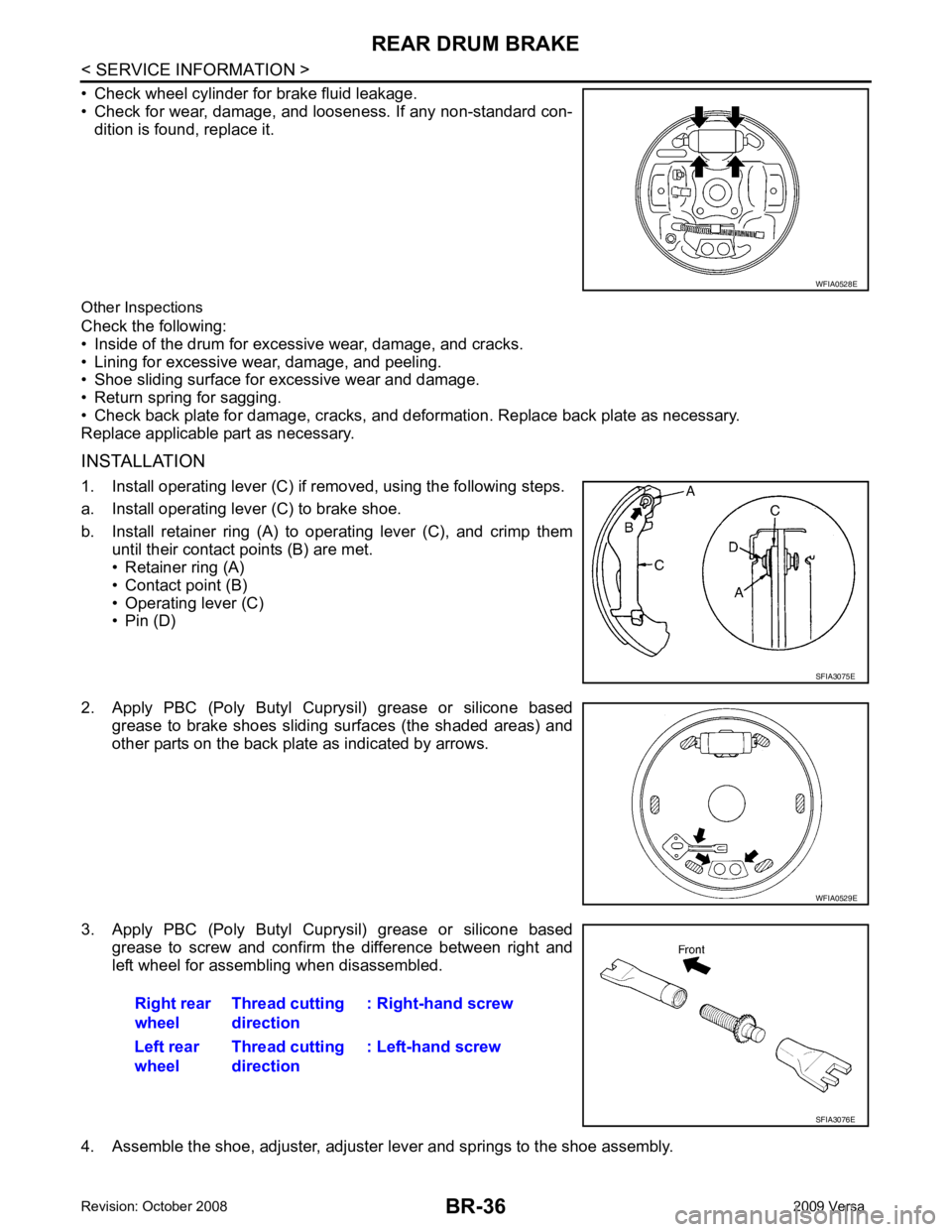
Wheel Cylinder Leakage Inspection Rear
Drum Brake " .
Repair limit thickness (A) : Refer to BR-40, " Rear
Drum Brake " .
Rear
Drum Brake " .
Repair limit inner diameter : Refer to BR-40, " Rear
Drum Brake " .
Page 836 of 4331
SFIA3075E
Page 837 of 4331
BR
N
O P
5. Connect the parking brake rear cable to the operating lever.
6. Install the shoe assembly. After assembly, be sure that each part is installed properly. CAUTION:
Do not damage the wheel cylinder piston boot.
7. Install the brake drum.
8. Depress brake pedal for several times (approximately 2 or 3 times).
9. Adjust clearance of brake shoe. Refer to PB-5, " On-Vehicle Service " .
10. Install rear wheel and tire. Refer to WT-7, " Rotation " .
Removal and Installati on of Wheel Cylinder INFOID:0000000004305917
REMOVAL 1. Drain the brake fluid. Refer to BR-9, " Drain and Refill " .
2. Remove the rear brake shoe assembly. Refer to BR-34, " Removal and Installation of Drum Brake Assem-
bly " .
3. Remove the bleed valve.
4. Disconnect the brake tube from the wheel cylinder.
5. Remove the wheel cylinder bolts and then remo ve the wheel cylinder from the back plate.
INSTALLATION Installation is in the reverse order of removal.
• Tighten bolts and bleed valve to the specified torque. Refer to BR-33, " Component " .
• Refill with new brake fluid and bleed the air. Refer to BR-9, " Bleeding Brake System " .
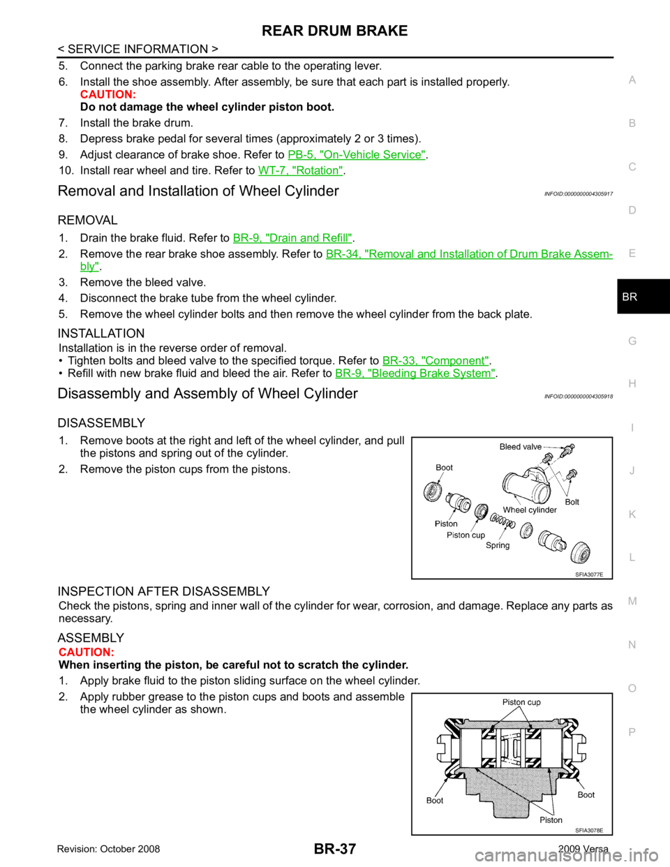
Disassembly and Assemb ly of Wheel Cylinder INFOID:0000000004305918
DISASSEMBLY 1. Remove boots at the right and left of the wheel cylinder, and pull the pistons and spring out of the cylinder.
2. Remove the piston cups from the pistons.
INSPECTION AFTER DISASSEMBLY Check the pistons, spring and inner wall of the cylinder for wear, corrosion, and damage. Replace any parts as
necessary.
ASSEMBLY CAUTION:
When inserting the piston, be caref ul not to scratch the cylinder.
1. Apply brake fluid to the piston sliding surface on the wheel cylinder.
2. Apply rubber grease to the piston cups and boots and assemble the wheel cylinder as shown.
Page 838 of 4331

Front brake Brake model CLZ25VF
Cylinder bore diameter 57.2 mm (2.252 in)
Pad
Length × width × thickness 125.6 mm
× 48.0 mm × 9.5 mm
(4.945 in × 1.890 in × 0.374 in)
Rotor outer diameter × thickness 280 mm × 24.0 mm (11.02 in × 0.945 in)
Rear brake Brake model LT23 Cylinder bore diameter 19.06 mm (0.750 in)
Drum inner diameter 228.6 mm (9.000 in)
Master cylinder Cylinder bore diameter 23.81 ± 0.015 mm (0.937 ± 0.001 in)
Brake booster Booster model C255 Diaphragm diameter 255 mm (10.04 in)
Recommended brake fluid DOT 3
Page 839 of 4331
SERVICE DATA AND SPECIFICATIONS (SDS)
BR-39
< SERVICE INFORMATION >
C
D E
G H
I
J
K L
M A
B BR
N
O P
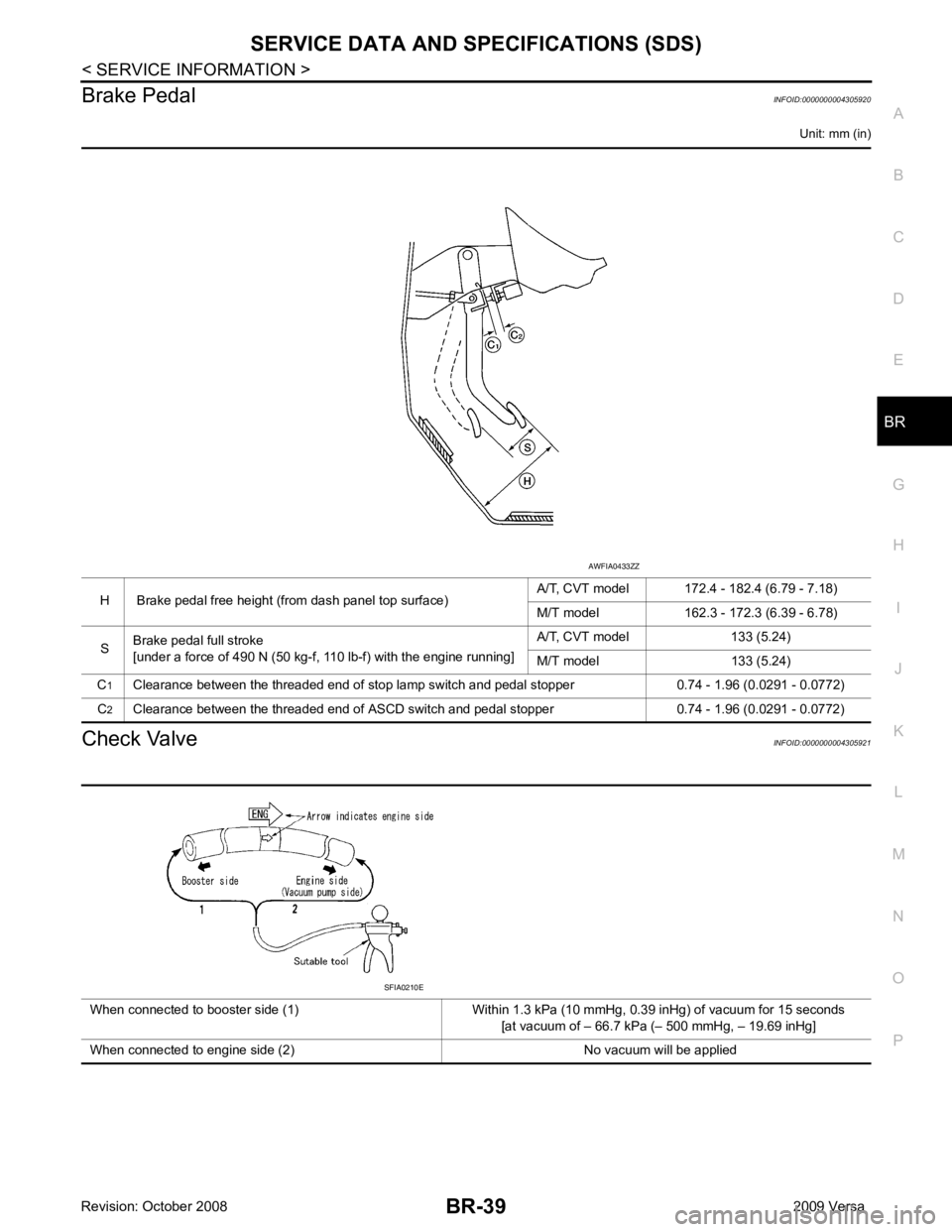
Brake Pedal
INFOID:0000000004305920
Unit: mm (in)
Check Valve INFOID:0000000004305921
H Brake pedal free height (from dash panel top surface)
A/T, CVT model 172.4 - 182.4 (6.79 - 7.18)
M/T model 162.3 - 172.3 (6.39 - 6.78)
S Brake pedal full stroke
[under a force of 490 N (50 kg-f, 110 lb-f) with the engine running] A/T, CVT model 133 (5.24)
M/T model 133 (5.24)
C 1
Clearance between the threaded end of stop lamp switch and pedal stopper 0.74 - 1.96 (0.0291 - 0.0772)
C 2
Clearance between the threaded end of ASCD switch and pedal stopper 0.74 - 1.96 (0.0291 - 0.0772) AWFIA0433ZZ
When connected to booster side (1) Within 1.3 kPa (10 mmHg, 0.39 inHg) of vacuum for 15 seconds [at vacuum of – 66.7 kPa (– 500 mmHg, – 19.69 inHg]
When connected to engine side (2) No vacuum will be applied SFIA0210E
Page 840 of 4331
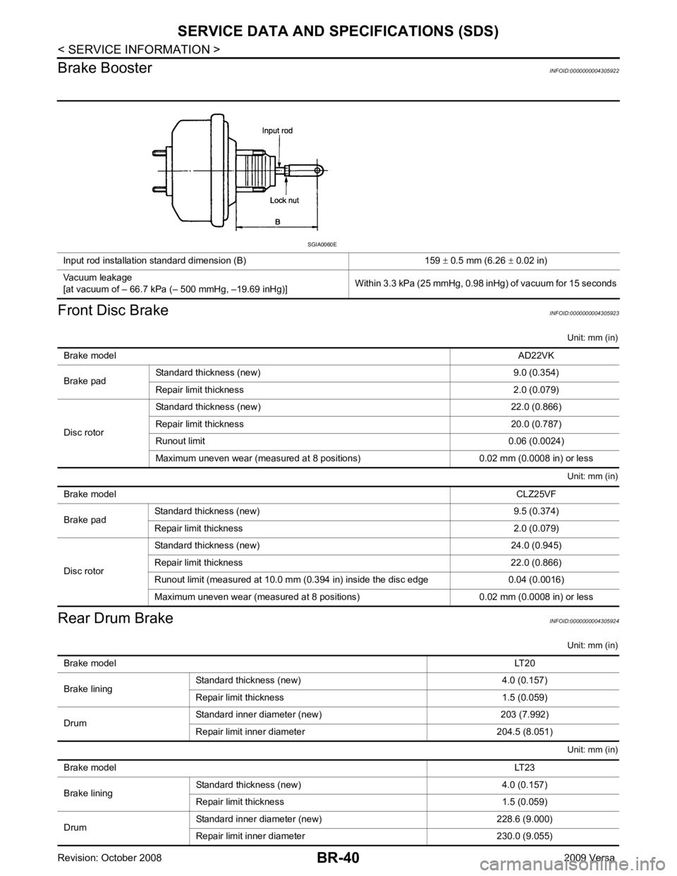
BR-40< SERVICE INFORMATION >
SERVICE DATA AND SPECIFICATIONS (SDS)
Brake Booster INFOID:0000000004305922
Front Disc Brake INFOID:0000000004305923
Unit: mm (in)
Unit: mm (in)
Rear Drum Brake INFOID:0000000004305924
Unit: mm (in)
Unit: mm (in)
Input rod installation standard dimension (B) 159
± 0.5 mm (6.26 ± 0.02 in)
Vacuum leakage
[at vacuum of – 66.7 kPa (– 500 mmHg, –19.69 inHg)] Within 3.3 kPa (25 mmHg, 0.98 inHg) of vacuum for 15 seconds SGIA0060E
Brake model AD22VK
Brake pad Standard thickness (new) 9.0 (0.354)
Repair limit thickness 2.0 (0.079)
Disc rotor Standard thickness (new) 22.0 (0.866)
Repair limit thickness 20.0 (0.787)
Runout limit 0.06 (0.0024)
Maximum uneven wear (measured at 8 positions) 0.02 mm (0.0008 in) or less Brake model
CLZ25VF
Brake pad Standard thickness (new) 9.5 (0.374)
Repair limit thickness 2.0 (0.079)
Disc rotor Standard thickness (new) 24.0 (0.945)
Repair limit thickness 22.0 (0.866)
Runout limit (measured at 10.0 mm (0.394 in) inside the disc edge 0.04 (0.0016)
Maximum uneven wear (measured at 8 positions) 0.02 mm (0.0008 in) or less Brake model
LT20
Brake lining Standard thickness
(new) 4.0 (0.157)
Repair limit thickness 1.5 (0.059)
Drum Standard inner diameter (new) 203 (7.992)
Repair limit inner diameter 204.5 (8.051) Brake model
LT23
Brake lining Standard thickness (new) 4.0 (0.157)
Repair limit thickness 1.5 (0.059)
Drum Standard inner diameter (new) 228.6 (9.000)
Repair limit inner diameter 230.0 (9.055)