cooling NISSAN LATIO 2009 Service Repair Manual
[x] Cancel search | Manufacturer: NISSAN, Model Year: 2009, Model line: LATIO, Model: NISSAN LATIO 2009Pages: 4331, PDF Size: 58.04 MB
Page 14 of 4331
AT
N
O P
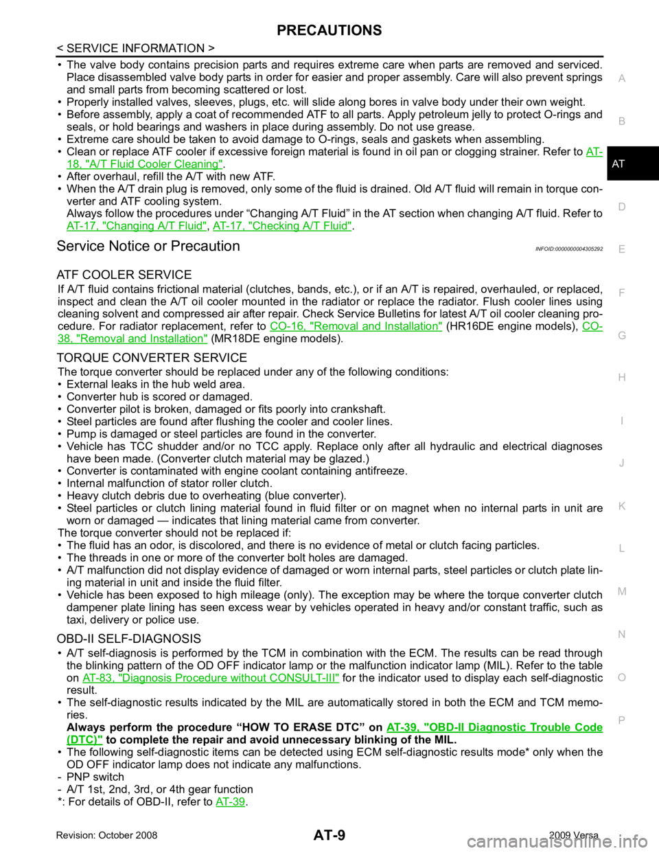
• The valve body contains precision parts and requires extreme care when parts are removed and serviced.
Place disassembled valve body parts in order for easier and proper assembly. Care will also prevent springs
and small parts from becoming scattered or lost.
• Properly installed valves, sleeves, plugs, etc. will slide along bores in valve body under their own weight.
• Before assembly, apply a coat of recommended ATF to all parts. Apply petroleum jelly to protect O-rings and
seals, or hold bearings and washers in pl ace during assembly. Do not use grease.
• Extreme care should be taken to avoid damage to O-rings, seals and gaskets when assembling.
• Clean or replace ATF cooler if excessive foreign material is found in oil pan or clogging strainer. Refer to AT-18, " A/T Fluid Cooler Cleaning " .
• After overhaul, refill the A/T with new ATF.
• When the A/T drain plug is removed, only some of the fluid is drained. Old A/T fluid will remain in torque con- verter and ATF cooling system.
Always follow the procedures under “Changing A/T Fluid” in the AT section when changing A/T fluid. Refer to
AT-17, " Changing A/T Fluid " ,
AT-17, " Checking A/T Fluid " .
Service Notice or Precaution INFOID:0000000004305292
ATF COOLER SERVICE If A/T fluid contains frictional material (clutches, bands, etc.), or if an A/T is repaired, overhauled, or replaced,
inspect and clean the A/T oil cooler mounted in the radiator or replace the radiator. Flush cooler lines using
cleaning solvent and compressed air after repair. Check Serv ice Bulletins for latest A/T oil cooler cleaning pro-
cedure. For radiator replacement, refer to CO-16, " Removal and Installation " (HR16DE engine models),
CO-38, " Removal and Installation " (MR18DE engine models).
TORQUE CONVERTER SERVICE The torque converter should be replaced under any of the following conditions:
• External leaks in the hub weld area.
• Converter hub is scored or damaged.
• Converter pilot is broken, damaged or fits poorly into crankshaft.
• Steel particles are found after flushing the cooler and cooler lines.
• Pump is damaged or steel particles are found in the converter.
• Vehicle has TCC shudder and/or no TCC apply. Replace only after all hydraulic and electrical diagnoses
have been made. (Converter clutch material may be glazed.)
• Converter is contaminated with engi ne coolant containing antifreeze.
• Internal malfunction of stator roller clutch.
• Heavy clutch debris due to overheating (blue converter).
• Steel particles or clutch lining material found in flui d filter or on magnet when no internal parts in unit are
worn or damaged — indicates that lining material came from converter.
The torque converter should not be replaced if:
• The fluid has an odor, is discolored, and there is no evidence of metal or clutch facing particles.
• The threads in one or more of the converter bolt holes are damaged.
• A/T malfunction did not display evidence of damaged or worn internal parts, steel particles or clutch plate lin-
ing material in unit and inside the fluid filter.
• Vehicle has been exposed to high mileage (only). The e xception may be where the torque converter clutch
dampener plate lining has seen excess wear by vehicles operated in heavy and/or constant traffic, such as
taxi, delivery or police use.
OBD-II SELF-DIAGNOSIS • A/T self-diagnosis is performed by the TCM in combination with the ECM. The results can be read through the blinking pattern of the OD OFF indicator lamp or the malfunction indicator lamp (MIL). Refer to the table
on AT-83, " Diagnosis Procedure without CONSULT-III " for the indicator used to display each self-diagnostic
result.
• The self-diagnostic results indicated by the MIL ar e automatically stored in both the ECM and TCM memo-
ries.
Always perform the procedure “HOW TO ERASE DTC” on AT-39, " OBD-II Diagnostic Trouble Code
(DTC) " to complete the repair and avo
id unnecessary blinking of the MIL.
• The following self-diagnostic items can be detected us ing ECM self-diagnostic results mode* only when the
OD OFF indicator lamp does not indicate any malfunctions.
- PNP switch
- A/T 1st, 2nd, 3rd, or 4th gear function
*: For details of OBD-II, refer to AT-39 .
Page 895 of 4331

CO
N
O P
CONTENTS
ENGINE COOLING SYSTEM
HR16DE
PRECAUTION ....... ........................................
3
PRECAUTIONS .............................................. .....3
Precaution for Supplemental Restraint System
(SRS) "AIR BAG" and "SEAT BELT PRE-TEN-
SIONER" ............................................................. ......
3
Precaution Necessary fo r Steering Wheel Rota-
tion After Battery Disconnect ............................... ......
3
Precaution for Liquid Gasket ............................... ......4
PREPARATION .... ........................................5
PREPARATION .............................................. .....5
Special Service Tool ........................................... ......5
Commercial Service Tool .................................... ......5
SYMPTOM DIAGNOSIS ..... ..........................7
OVERHEATING CAUSE ANALYSIS ............. .....7
Troubleshooting Chart ..... ..........................................7
FUNCTION DIAGNOSIS .. .............................9
DESCRIPTION ............................................... .....9
Engine Cooling System ....................................... ......9
Engine Cooling System Schematic ..................... ....10
ON-VEHICLE MAINTENA NCE ....................11
ENGINE COOLANT ....................................... ....11
Inspection ............................................................ ....11
Changing Engine Coolant ................................... ....11
RADIATOR ..................................................... ....14
Checking Radiator Cap ....................................... ....14
Checking Radiator ............................................... ....14
ON-VEHICLE REPAIR .... .............................16
RADIATOR ..................................................... ....16 Component ..........................................................
....16
Removal and Installation ..................................... ....16
COOLING FAN .................................................. 18
Component (Models with A/C) ............................. ....18
Component (Models without A/C) ........................ ....18
Removal and Installation ..................................... ....19
WATER PUMP .................................................. 20
Exploded View ..................................................... ....20
Removal and Installation ..................................... ....20
Inspection ............................................................ ....21
THERMOSTAT .................................................. 22
Exploded View ..................................................... ....22
Removal and Installation ..................................... ....22
Inspection ............................................................ ....23
WATER OUTLET .............................................. 24
Exploded View ..................................................... ....24
Removal and Installation ..................................... ....24
Inspection ............................................................ ....25
DISASSEMBLY AND AS SEMBLY ..............26
COOLING FAN .................................................. 26
Disassembly and Assembly ................................. ....26
SERVICE DATA AND SPECIFICATIONS
(SDS) ............... .............................................
27
SERVICE DATA AND SPECIFICATIONS
(SDS) ................................................................. 27
Periodical Maintenance Specification .................. ....27
Radiator ............................................................... ....27
Thermostat .......................................................... ....27
MR18DE
SERVICE INFORMATION .. .........................28
PRECAUTIONS ................................................. 28
Page 899 of 4331
CO
NP
O
PREPARATION
PREPARATION
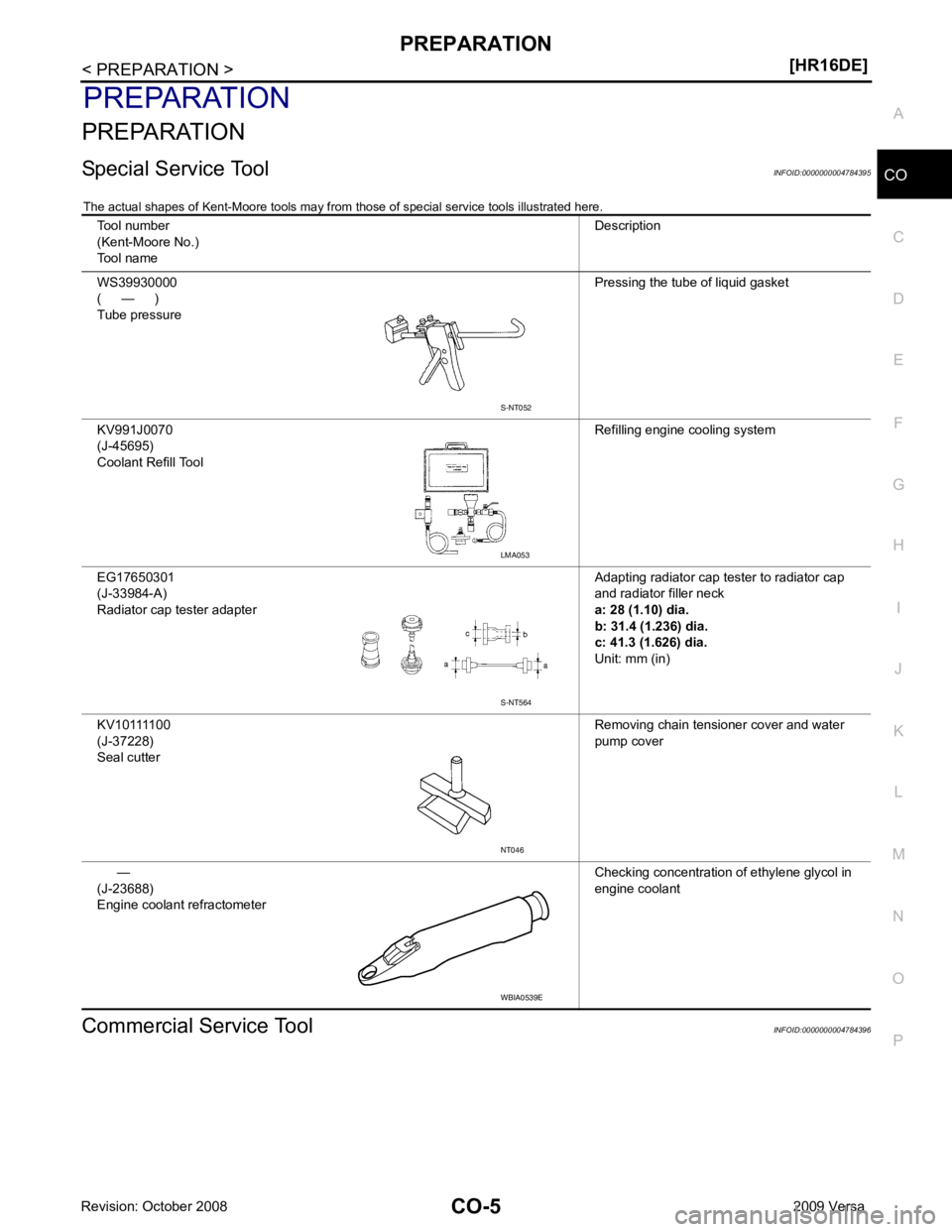
Special Service Tool INFOID:0000000004784395
The actual shapes of Kent-Moore tools may from those of special service tools illustrated here.
Commercial Service Tool INFOID:0000000004784396
Tool number
(Kent-Moore No.)
Tool name Description
WS39930000
( — )
Tube pressure Pressing the tube of liquid gasket
KV991J0070
(J-45695)
Coolant Refill Tool Refilling engine cooling system
EG17650301
(J-33984-A)
Radiator cap tester adapter Adapting radiator cap tester to radiator cap
and radiator filler neck
a: 28 (1.10) dia.
b: 31.4 (1.236) dia.
c: 41.3 (1.626) dia.
Unit: mm (in)
KV10111100
(J-37228)
Seal cutter Removing chain tensioner cover and water
pump cover
—
(J-23688)
Engine coolant refractometer Checking concentration of ethylene glycol in
engine coolant LMA053
S-NT564
WBIA0539E
Page 901 of 4331
CO
NP
O
SYMPTOM DIAGNOSIS
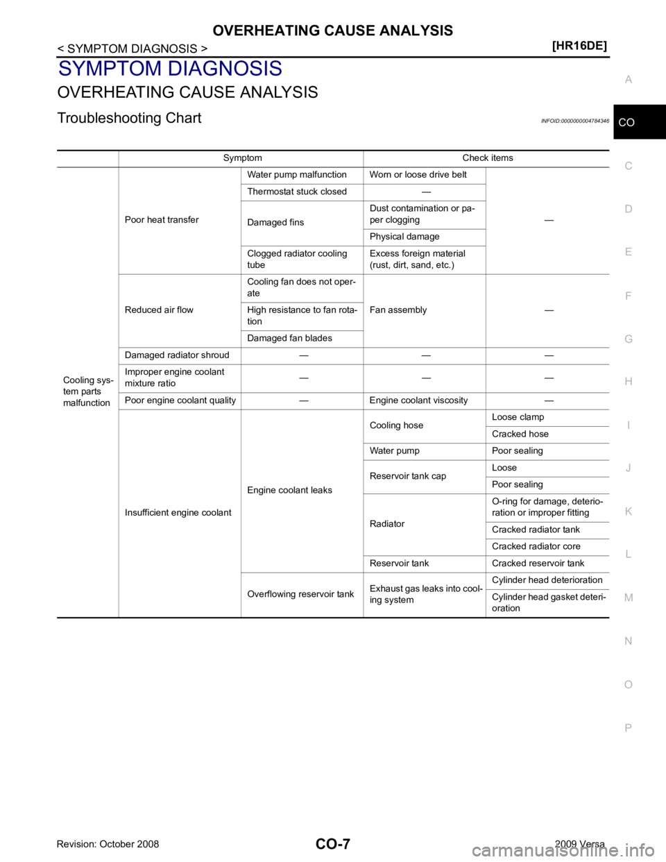
OVERHEATING CAUSE ANALYSIS
Troubleshooting Chart INFOID:0000000004784346
Symptom Check items
Cooling sys-
tem parts
malfunction Poor heat transfer
Water pump malfunction Worn or loose drive belt
—
Thermostat stuck closed —
Damaged fins Dust contamination or pa-
per clogging
Physical damage
Clogged radiator cooling
tube Excess foreign material
(rust, dirt, sand, etc.)
Reduced air flow Cooling fan does not oper-
ate
Fan assembly —
High resistance to fan rota-
tion
Damaged fan blades
Damaged radiator shroud — — —
Improper engine coolant
mixture ratio — — —
Poor engine coolant quality — Engine coolant viscosity —
Insufficient engine coolant Engine coolant leaks Cooling hose
Loose clamp
Cracked hose
Water pump Poor sealing
Reservoir tank cap Loose
Poor sealing
Radiator O-ring for damage, deterio-
ration or improper fitting
Cracked radiator tank
Cracked radiator core
Reservoir tank Cracked reservoir tank
Overflowing reservoir tank Exhaust gas leaks into cool-
ing system Cylinder head deterioration
Cylinder head gasket deteri-
oration
Page 903 of 4331
CO
NP
O
FUNCTION DIAGNOSIS
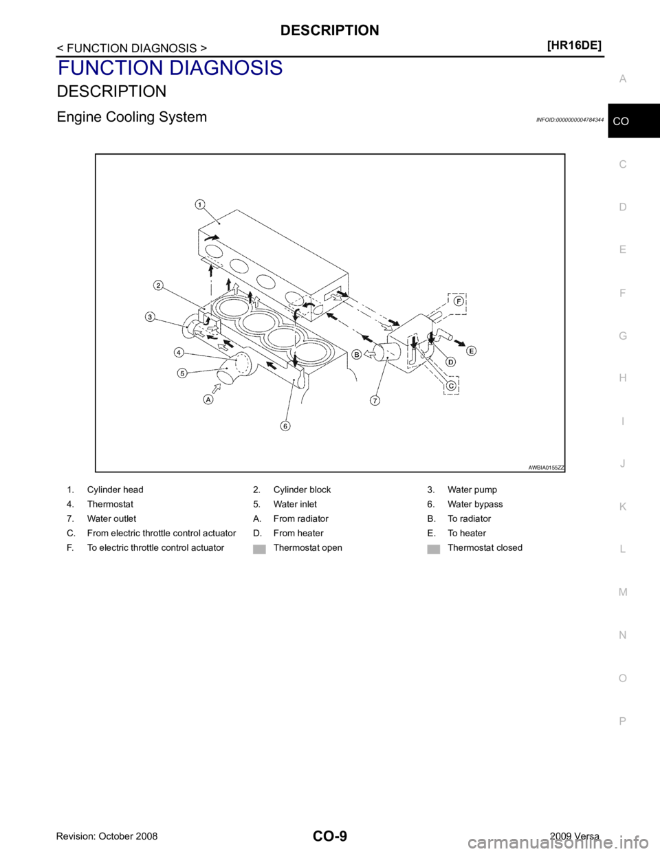
DESCRIPTION
Engine Cooling System INFOID:0000000004784344
Page 905 of 4331
CO
NP
O
ON-VEHICLE MAINTENANCE
ENGINE COOLANT
Inspection INFOID:0000000004784397
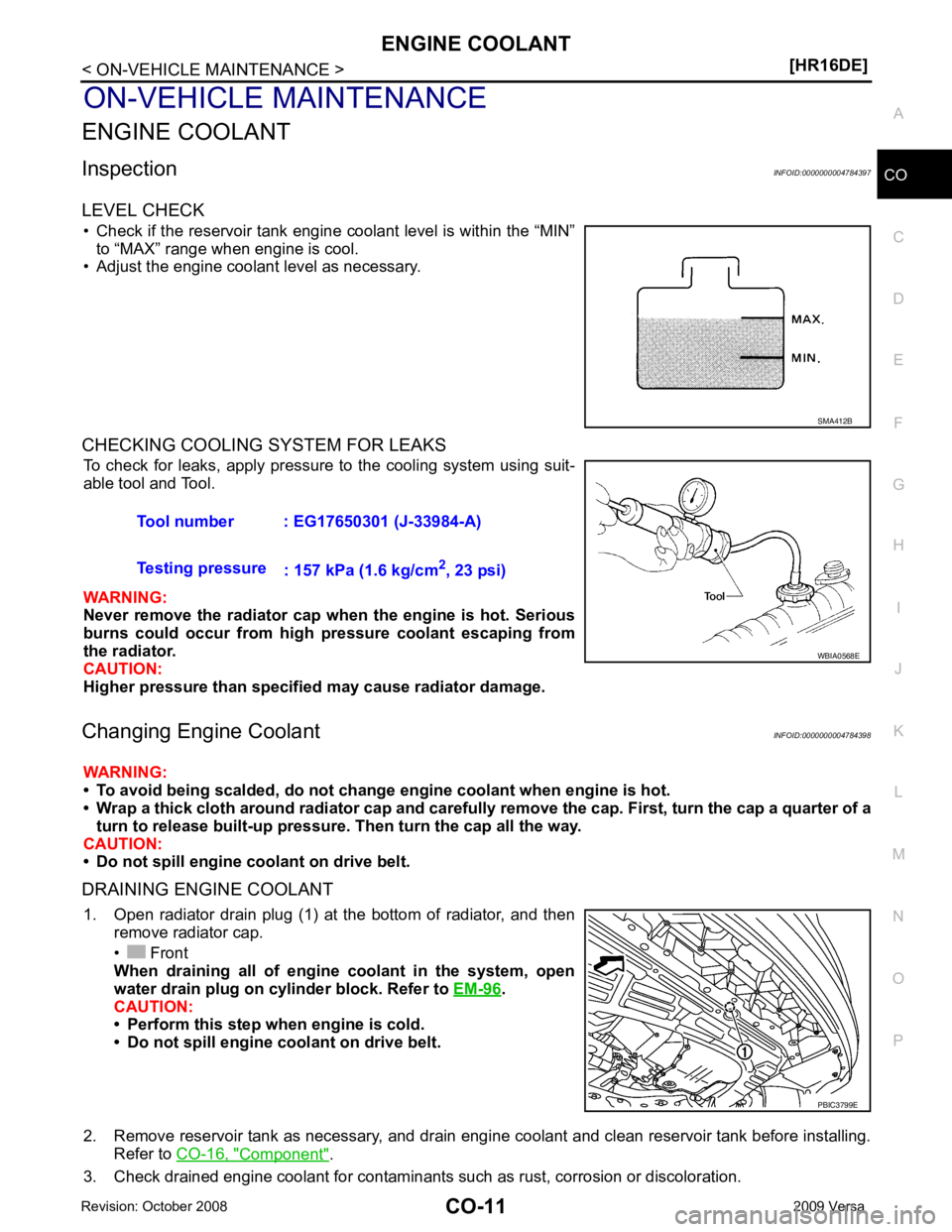
LEVEL CHECK • Check if the reservoir tank engine coolant level is within the “MIN” to “MAX” range when engine is cool.
• Adjust the engine coolant level as necessary.
CHECKING COOLING SYSTEM FOR LEAKS To check for leaks, apply pressure to the cooling system using suit-
able tool and Tool.
WARNING:
Never remove the radiator cap wh en the engine is hot. Serious
burns could occur from high pressure coolant escaping from
the radiator.
CAUTION:
Higher pressure than specified may cause radiator damage.
Changing Engine Coolant INFOID:0000000004784398
WARNING:
• To avoid being scalded, do not change engine coolant when engine is hot.
• Wrap a thick cloth around radiator cap and carefully remove the cap. First, turn the cap a quarter of a
turn to release built-up pressure. Then turn the cap all the way.
CAUTION:
• Do not spill engine coolant on drive belt.
DRAINING ENGINE COOLANT 1. Open radiator drain plug (1) at the bottom of radiator, and then remove radiator cap.
• Front
When draining all of engine coolant in the system, open
water drain plug on cylinder block. Refer to EM-96 .
CAUTION:
• Perform this step when engine is cold.
• Do not spill engine coolant on drive belt.
2. Remove reservoir tank as necessary, and drain engi ne coolant and clean reservoir tank before installing.
Refer to CO-16, " Component " .
3. Check drained engine coolant for contaminants such as rust, corrosion or discoloration. PBIC3799E
Page 907 of 4331
CO
NP
O
10. Place the coolant container (with the refill hose inserted)
at the same level as the top of the radiator. Then
open the ball valve on the refill hose so the coolant will be drawn up to fill the cooling system. The cooling
system is full when the vacuum gauge reads zero.
CAUTION:
Do not allow the coolant container to get too low when filling, to avoid air from being drawn into
the cooling system.
11. Remove the Tool from the radiator neck opening.
12. Fill the cooling system reservoir tank to the specif ied level and install the radiator cap. Run the engine to
warm up the cooling system and top up the system as necessary.
FLUSHING COOLING SYSTEM 1. Install reservoir tank if removed. Refer to CO-16, " Component " .
2. Install radiator drain plug. •If water drain plug on cylinder block is removed, close and tighten it. Refer to EM-96, " Disassem-
bly and Assembly " .
CAUTION:
Be sure to clean radiator drain plug and install with new O-ring. Refer to CO-16, " Component " .
3. Fill radiator and reservoir tank with water and reinstall radiator cap.
4. Run engine and warm it up to normal operating temperature.
5. Rev engine two or three times under no-load.
6. Stop engine and wait until it cools down.
7. Drain water from the cooling system.
8. Repeat steps 1 through 7 until clear water begins to drain from radiator.
Page 913 of 4331
CO
NP
O
Removal and Installation
INFOID:0000000004784360
REMOVAL 1. Drain engine coolant from radiator. Refer to CO-11, " Changing Engine Coolant " .
CAUTION:
• Perform this step when engine is cold.
• Do not spill engine coolant on drive belt.
2. Remove air duct (inlet). Refer to EM-26, " Exploded View " .
3. Remove reservoir tank.
4. Disconnect radiator hose (upper) at radiator side. Refer to CO-16, " Component " .
5. Disconnect harness connectors from fan motor, and move harness to aside.
6. Remove cooling fan assembly. CAUTION:
Be careful not to damage or scratch the radiator core.
INSTALLATION Installation is the reverse order of removal.
• Cooling fans are controlled by ECM. For details, refer to EC-422, " Description " .
CAUTION:
Be careful not to damage or scratch the radiator core.
Page 924 of 4331
![NISSAN LATIO 2009 Service Repair Manual CO-30< SERVICE INFORMATION >
[MR18DE]
PREPARATION
PREPARATION
Special Service Tool INFOID:0000000004673018
The actual shapes of Kent-Moore tools may from those of special service tools illustrated he NISSAN LATIO 2009 Service Repair Manual CO-30< SERVICE INFORMATION >
[MR18DE]
PREPARATION
PREPARATION
Special Service Tool INFOID:0000000004673018
The actual shapes of Kent-Moore tools may from those of special service tools illustrated he](/img/5/57359/w960_57359-923.png)
CO-30< SERVICE INFORMATION >
[MR18DE]
PREPARATION
PREPARATION
Special Service Tool INFOID:0000000004673018
The actual shapes of Kent-Moore tools may from those of special service tools illustrated here.
Commercial Service Tool INFOID:0000000004673019
Tool number
(Kent-Moore No.)
Tool name Description
WS39930000
( — )
Tube pressure Pressing the tube of liquid gasket
KV991J0070
(J-45695)
Coolant Refill Tool Refilling engine cooling system
EG17650301
(J-33984-A)
Radiator cap tester adapter Adapting radiator cap tester to radiator cap
and radiator filler neck
a: 28 (1.10) dia.
b: 31.4 (1.236) dia.
c: 41.3 (1.626) dia.
Unit: mm (in)
KV10111100
(J-37228)
Seal cutter Removing chain tensioner cover and water
pump cover
—
(J-23688)
Engine coolant refractometer Checking concentration of ethylene glycol in
engine coolant S-NT052
LMA053
S-NT564
NT046
WBIA0539E
Page 929 of 4331
![NISSAN LATIO 2009 Service Repair Manual ENGINE COOLANT
CO-35
< SERVICE INFORMATION >
[MR18DE] C
D E
F
G H
I
J
K L
M A CO
NP
O
ENGINE COOLANT
Inspection INFOID:0000000004305234
LEVEL CHECK • Check if the reservoir tank engine coolant level NISSAN LATIO 2009 Service Repair Manual ENGINE COOLANT
CO-35
< SERVICE INFORMATION >
[MR18DE] C
D E
F
G H
I
J
K L
M A CO
NP
O
ENGINE COOLANT
Inspection INFOID:0000000004305234
LEVEL CHECK • Check if the reservoir tank engine coolant level](/img/5/57359/w960_57359-928.png)
ENGINE COOLANT
CO-35
< SERVICE INFORMATION >
[MR18DE] C
D E
F
G H
I
J
K L
M A CO
NP
O
ENGINE COOLANT
Inspection INFOID:0000000004305234
LEVEL CHECK • Check if the reservoir tank engine coolant level is within the “MIN” to “MAX” range when engine is cool.
• Adjust the engine coolant level as necessary.
CHECKING COOLING SYSTEM FOR LEAKS To check for leaks, apply pressure to the cooling system using suit-
able tool and Tool.
WARNING:
Never remove the radiator cap wh en the engine is hot. Serious
burns could occur from high pressure coolant escaping from
the radiator.
CAUTION:
Higher pressure than specified may cause radiator damage.
Changing Engine Coolant INFOID:0000000004673021
WARNING:
• To avoid being scalded, do not change engine coolant when engine is hot.
• Wrap a thick cloth around radiator cap and carefully remove the cap. First, turn the cap a quarter of a
turn to release built-up pressure. Then turn the cap all the way.
CAUTION:
• Do not spill engine coolant on drive belt.
DRAINING ENGINE COOLANT 1. Open radiator drain plug (1) at the bottom of radiator, and then remove radiator cap.
• Front
When draining all of engine coolant in the system, open
water drain plug on cylinder block. Refer to EM-200 .
CAUTION:
• Perform this step when engine is cold.
• Do not spill engine coolant on drive belt.
2. Remove reservoir tank as necessary, and drain engi ne coolant and clean reservoir tank before installing.
Refer to CO-38, " Component " .
3. Check drained engine coolant for contaminants such as rust, corrosion or discoloration. If contaminated, flush the engine cooling system. SMA412B
Tool number : EG17650301 (J-33984-A)
Testing pressure : 157 kPa (1.6 kg/cm 2
, 23 psi) WBIA0568E
PBIC3799E