battery location NISSAN LATIO 2010 Service Owner's Manual
[x] Cancel search | Manufacturer: NISSAN, Model Year: 2010, Model line: LATIO, Model: NISSAN LATIO 2010Pages: 3745, PDF Size: 73.67 MB
Page 3384 of 3745

PG-1
ELECTRICAL
C
DE
F
G H
I
J
L
M
SECTION PG
A
B
PG
N
O P
CONTENTS
POWER SUPPLY, GROUND & CIRCUIT ELEMENTS
SERVICE INFORMATION .. ..........................2
PRECAUTIONS .............................................. .....2
Precaution for Supplemental Restraint System
(SRS) "AIR BAG" and "SEAT BELT PRE-TEN-
SIONER" ............................................................. ......
2
Precaution Necessary for Steering Wheel Rota-
tion After Battery Disconnect ............................... ......
2
POWER SUPPLY ROUTING CIRCUIT ...............4
Schematic ........................................................... ......4
Wiring Diagram - POWER - ......................................6
Fuse ........................................................................16
Fusible Link .............................................................16
Circuit Breaker (Built Into BCM) ..............................16
Circuit Breaker ........................................................16
IPDM E/R (INTELLIGENT POWER DISTRI-
BUTION MODULE ENGINE ROOM) .................
17
System Description ............................................. ....17
CAN Communication System Description ...............18
Function of Detecting Ignition Relay Malfunction ....18
CONSULT-III Function (IPDM E/R) ..................... ....18
Auto Active Test ......................................................20
IPDM E/R Terminal Arrangement - Type A .............23
IPDM E/R Terminal Arrangement - Type B .............24
Terminal and Reference Value for IPDM E/R .........25
IPDM E/R Power/Ground Circuit Inspection ...........27
Inspection with CONSULT-III (Self-Diagnosis) .......28
Removal and Installation of IPDM E/R ................ ....28
GROUND CIRCUIT ...........................................30
Ground Distribution .............................................. ....30
HARNESS .........................................................39
Harness Layout ................................................... ....39
Wiring Diagram Codes (Cell Codes) .......................59
ELECTRICAL UNITS LOCATION ....................62
Electrical Units Location ..........................................62
HARNESS CONNECTOR .................................66
Description ...............................................................66
ELECTRICAL UNITS ........................................69
Terminal Arrangement .............................................69
STANDARDIZED RELAY .................................70
Description ...............................................................70
SUPER MULTIPLE JUNCTION (SMJ) .............72
Terminal Arrangement .............................................72
FUSE BLOCK-JUNCTION BOX (J/B) ..............74
Terminal Arrangement .............................................74
FUSE AND FUSIBLE LINK BOX ......................75
Terminal Arrangement .............................................75
Revision: January 20102010 Versa
Page 3579 of 3745

FRONT SEATSE-13
< SERVICE INFORMATION >
C
DE
F
G H
J
K L
M A
B
SE
N
O P
1. Disconnect the negative and positive battery term inals, then wait at least three minutes.
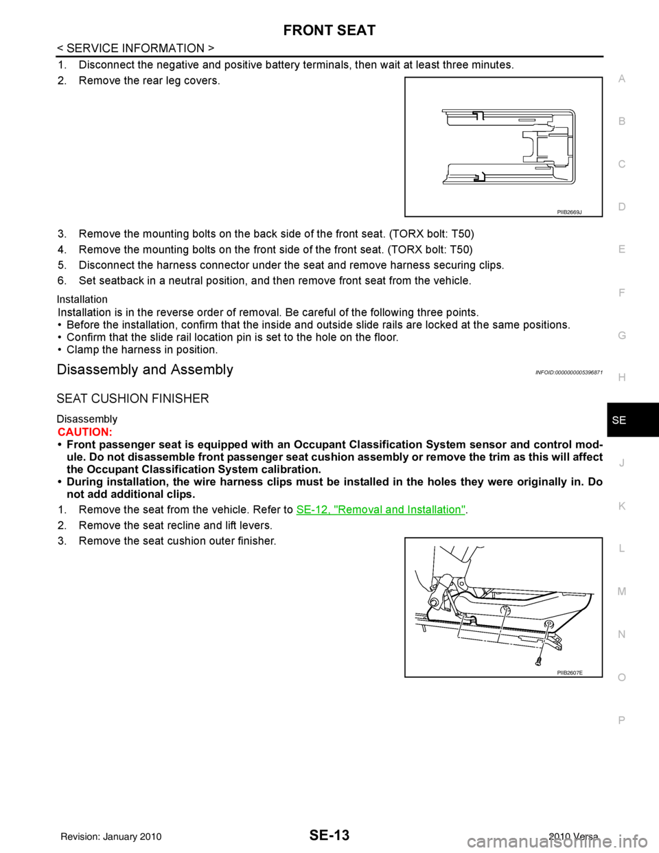
2. Remove the rear leg covers.
3. Remove the mounting bolts on the back si de of the front seat. (TORX bolt: T50)
4. Remove the mounting bolts on the front side of the front seat. (TORX bolt: T50)
5. Disconnect the harness connector under the seat and remove harness securing clips.
6. Set seatback in a neutral position, and t hen remove front seat from the vehicle.
Installation
Installation is in the reverse order of removal. Be careful of the following three points.
• Before the installation, confirm that the inside and outside slide rails are locked at the same positions.
• Confirm that the slide rail location pin is set to the hole on the floor.
• Clamp the harness in position.
Disassembly and AssemblyINFOID:0000000005396871
SEAT CUSHION FINISHER
Disassembly
CAUTION:
• Front passenger seat is equipped with an Occupant Classification System sensor and control mod-
ule. Do not disassemble front passenger seat cushion assembly or remove the trim as this will affect
the Occupant Classificatio n System calibration.
• During installation, the wire harn ess clips must be installed in the holes they were originally in. Do
not add additional clips.
1. Remove the seat from the vehicle. Refer to SE-12, "
Removal and Installation".
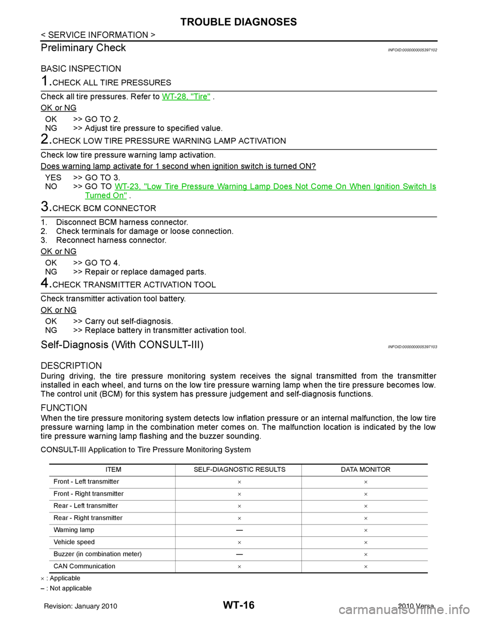
2. Remove the seat recline and lift levers.
3. Remove the seat cushion outer finisher.
PIIB2669J
PIIB2607E
Revision: January 20102010 Versa
Page 3594 of 3745

SRS-1
RESTRAINTS
C
DE
F
G
I
J
K L
M
SECTION SRS
A
B
SRS
N
O P
CONTENTS
SUPPLEMENTAL RESTRAINT SYSTEM (SRS)
PRECAUTION ....... ........................................2
PRECAUTIONS .............................................. .....2
Precaution for Supplemental Restraint System
(SRS) "AIR BAG" and "SEAT BELT PRE-TEN-
SIONER" ............................................................. ......
2
Precaution for SRS "AIR BAG" and "SEAT BELT
PRE-TENSIONER" Service ......................................
2
Precaution Necessary for Steering Wheel Rota-
tion After Battery Disconnect ............................... ......
2
Occupant Classification System Precaution .............3
SYMPTOM DIAGNOSIS ...............................4
SUPPLEMENTAL RESTRAINT SYSTEM
(SRS) .............................................................. .....
4
SRS Configuration .............................................. ......4
Driver Air Bag Module ...............................................5
Front Passenger Air Bag Module ..............................5
Front Side Air Bag ............................................... ......5
Side Curtain Air Bag ..................................................5
Front Seat Belt Pre-tensioner with Load Limiter .......6
Occupant Classification System (OCS) ....................6
Direct-connect SRS Component Connectors ............7
TROUBLE DIAGNOSIS ......................................8
Trouble Diagnosis Introduction ........................... ......8
SRS Component Parts Location .............................10
Schematic ...............................................................11
Wiring Diagram - SRS- ............................................12
CONSULT-III Function (AIR BAG) ..........................17
Self-Diagnosis Function (Without CONSULT-III) ....18
SRS Operation Check ......................................... ....19
Trouble Diagnosis with CONSULT-III .....................20
Trouble Diagnosis without CONSULT-III ................28
Trouble Diagnosis: "AIR BAG" Warning Lamp
Does Not Turn Off ...................................................
31
Trouble Diagnosis: "AIR BAG" Warning Lamp
Does Not Turn On ............................................... ....
32
ON-VEHICLE REPAIR .................................34
DRIVER AIR BAG MODULE ............................34
Removal and Installation ..................................... ....34
SPIRAL CABLE ................................................37
Removal and Installation .........................................37
FRONT PASSENGER AIR BAG MODULE ......39
Removal and Installation .........................................39
SIDE CURTAIN AIR BAG MODULE ................40
Component ..............................................................40
Removal and Installation .........................................40
CRASH ZONE SENSOR ...................................42
Removal and Installation ..................................... ....42
SIDE AIR BAG (SATELLITE) SENSOR ...........43
Removal and Installation .........................................43
FRONT SEAT BELT PRE-TENSIONER ...........44
Removal and Installation .........................................44
DIAGNOSIS SENSOR UNIT .............................45
Removal and Installation .........................................45
OCCUPANT CLASSIFICATION SYSTEM
CONTROL UNIT ................................................
47
Removal and Installation .........................................47
COLLISION DIAGNOSIS ..................................48
For Frontal Collision ................................................48
For Side and Rollover Collision ...............................50
Revision: January 20102010 Versa
Page 3647 of 3745

STC-1
STEERING
C
DE
F
H I
J
K L
M
SECTION STC
A
B
STC
N
O P
CONTENTS
STEERING CONTROL SYSTEM
EPS
BASIC INSPECTION ....... .............................
3
DIAGNOSIS AND REPAIR WORKFLOW ..... .....3
Work Flow ........................................................... ......3
SYSTEM DESCRIPTION ..............................5
EPS SYSTEM ... .............................................. .....5
System Diagram .................................................. ......5
System Description ...................................................5
Component Parts Location ........................................6
Component Description .............................................6
DIAGNOSIS SYSTEM (EPS CONTROL UNIT)
.....
8
CONSULT-III Function ........................................ ......8
DTC/CIRCUIT DIAGNOSIS ..........................9
C1601 BATTERY POWER SUPPLY ..................9
Description .......................................................... ......9
DTC Logic .................................................................9
Diagnosis Procedure .................................................9
C1604 TORQUE SENSOR .................................11
Description ..............................................................11
DTC Logic ...............................................................11
Diagnosis Procedure ...............................................11
C1606 EPS MOTOR ...........................................13
Description .......................................................... ....13
DTC Logic ...............................................................13
Diagnosis Procedure ...............................................13
Component Inspection ............................................13
C1607, C1608 EPS CONTROL UNIT ................15
Description .......................................................... ....15
DTC Logic ...............................................................15
Diagnosis Procedure ...............................................15
C1609 VEHICLE SPEED SIGNAL .....................16
Description ........................................................... ....16
DTC Logic ................................................................16
Diagnosis Procedure ...............................................16
C1610 ENGINE STATUS SIGNAL ...................17
Description ...............................................................17
DTC Logic ................................................................17
Diagnosis Procedure ...............................................17
U1000 CAN COMM CIRCUIT ...........................18
Description ...............................................................18
DTC Logic ................................................................18
Diagnosis Procedure ...............................................18
EPS WARNING LAMP ......................................19
Description ...............................................................19
Component Function Check ....................................19
Diagnosis Procedure ...............................................19
ECU DIAGNOSIS INFORMATION ..............20
EPS CONTROL UNIT .......................................20
Reference Value .................................................. ....20
Wiring Diagram - ELECTRONICALLY CON-
TROLLED POWER STEERING SYSTEM - ............
22
Fail-Safe .............................................................. ....23
DTC Inspection Priority Chart ..................................24
DTC Index ...............................................................24
SYMPTOM DIAGNOSIS ..............................25
EPS WARNING LAMP DOES NOT TURN ON ...25
Description ........................................................... ....25
Diagnosis Procedure ...............................................25
EPS WARNING LAMP DOES NOT TURN
OFF ....................................................................
26
Description ...............................................................26
Diagnosis Procedure ...............................................26
STEERING WHEEL TURNING FORCE IS
HEAVY OR LIGHT ............................................
27
Revision: January 20102010 Versa
Page 3693 of 3745

WT-16
< SERVICE INFORMATION >
TROUBLE DIAGNOSES
Preliminary Check
INFOID:0000000005397102
BASIC INSPECTION
1.CHECK ALL TIRE PRESSURES
Check all tire pressures. Refer to WT-28, "
Tire" .
OK or NG
OK >> GO TO 2.
NG >> Adjust tire pressure to specified value.
2.CHECK LOW TIRE PRESSURE WARNING LAMP ACTIVATION
Check low tire pressure warning lamp activation.
Does warning lamp activate for 1 second when ignition switch is turned ON?
YES >> GO TO 3.
NO >> GO TO WT-23, "
Low Tire Pressure Warning Lamp Does Not Come On When Ignition Switch Is
Turned On" .
3.CHECK BCM CONNECTOR
1. Disconnect BCM harness connector.
2. Check terminals for damage or loose connection.
3. Reconnect harness connector.
OK or NG
OK >> GO TO 4.
NG >> Repair or replace damaged parts.
4.CHECK TRANSMITTER ACTIVATION TOOL
Check transmitter activation tool battery.
OK or NG
OK >> Carry out self-diagnosis.
NG >> Replace battery in transmitter activation tool.
Self-Diagnosis (With CONSULT-III)INFOID:0000000005397103
DESCRIPTION
During driving, the tire pressure monitoring system receives the signal trans mitted from the transmitter
installed in each wheel, and turns on the low tire pressure warning lamp when the tire pressure becomes low.
The control unit (BCM) for this system has pressure judgement and self-diagnosis functions.
FUNCTION
When the tire pressure monitoring system detects low inflation pressure or an internal malfunction, the low tire
pressure warning lamp in the combination meter comes on. The malfunction location is indicated by the low
tire pressure warning lamp flashing and the buzzer sounding.
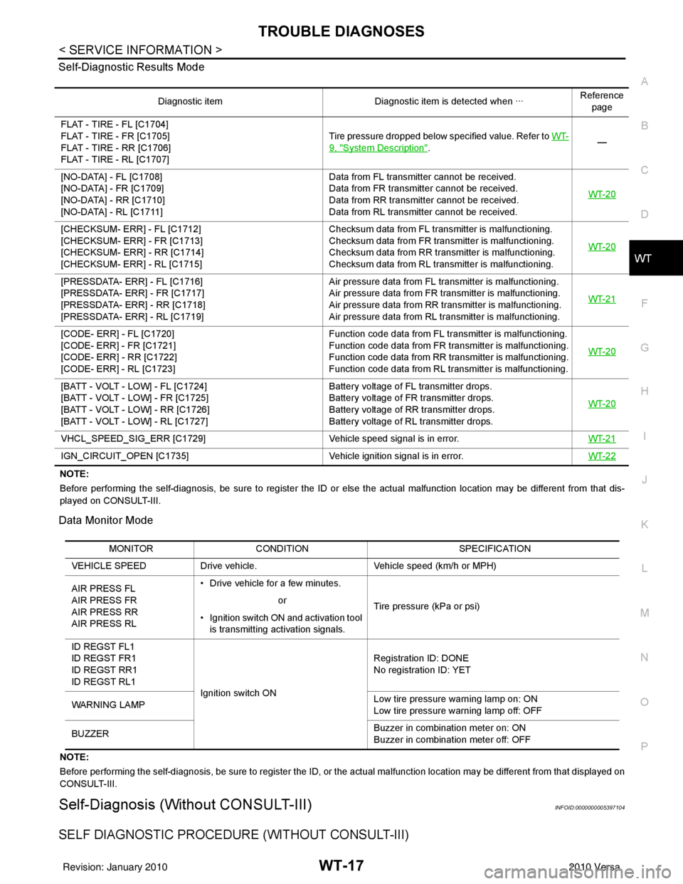
CONSULT-III Application to Tire Pressure Monitoring System
× : Applicable
– : Not applicable ITEM
SELF-DIAGNOSTIC RESULTS DATA MONITOR
Front - Left transmitter ××
Front - Right transmitter ××
Rear - Left transmitter ××
Rear - Right transmitter ××
Warning lamp —×
Vehicle speed ××
Buzzer (in combination meter) —×
CAN Communication ××
Revision: January 20102010 Versa
Page 3694 of 3745

TROUBLE DIAGNOSESWT-17
< SERVICE INFORMATION >
C
DF
G H
I
J
K L
M A
B
WT
N
O P
Self-Diagnostic Results Mode
NOTE:
Before performing the self-diagnosis, be sure to register the ID or else the actual malfunction location may be different from
that dis-
played on CONSULT-III.
Data Monitor Mode
NOTE:
Before performing the self-diagnosis, be sure to register the ID, or the actual malfunction location may be different from that displayed on
CONSULT-III.
Self-Diagnosis (Without CONSULT-III)INFOID:0000000005397104
SELF DIAGNOSTIC PROCE DURE (WITHOUT CONSULT-III)
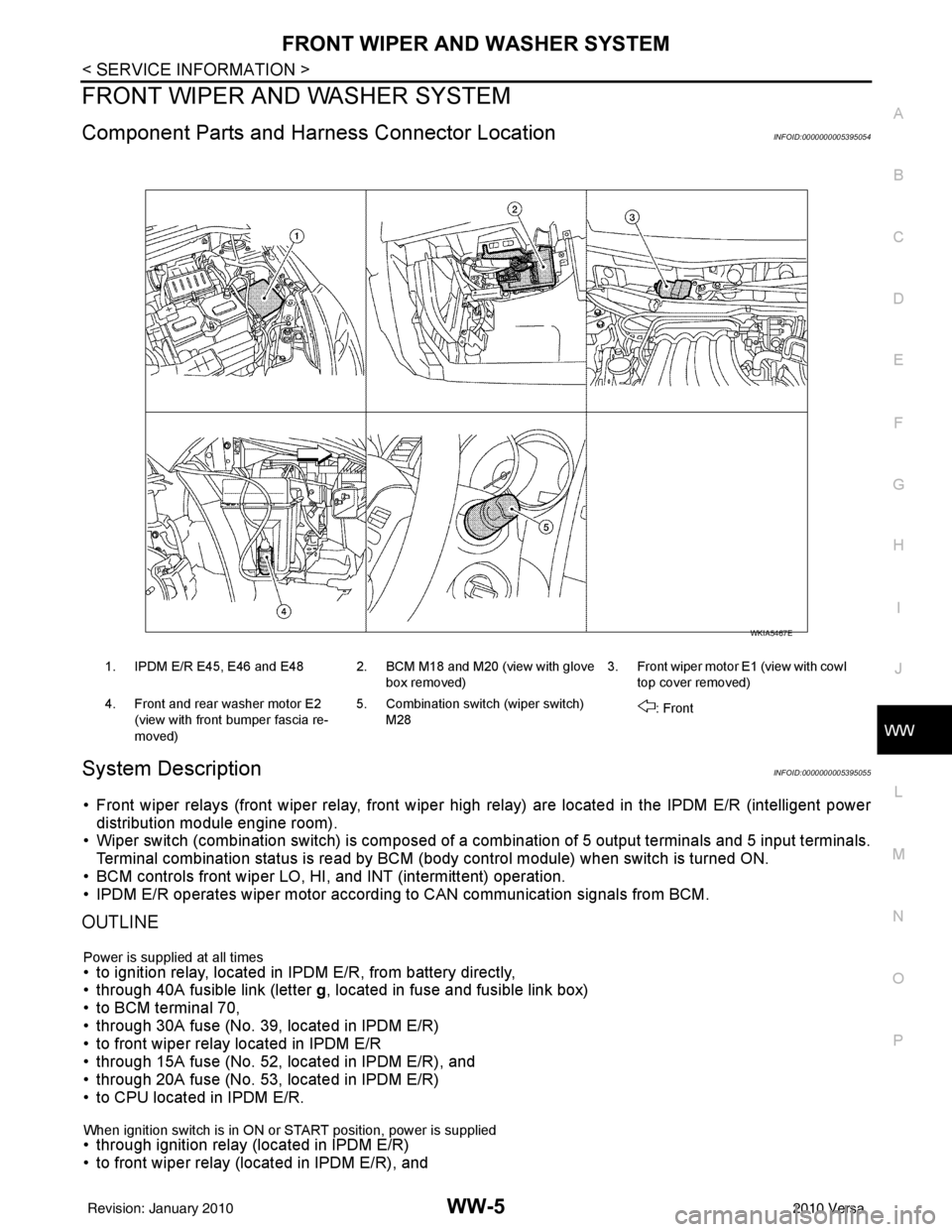
Diagnostic item Diagnostic item is detected when ···Reference
page
FLAT - TIRE - FL [C1704]
FLAT - TIRE - FR [C1705]
FLAT - TIRE - RR [C1706]
FLAT - TIRE - RL [C1707] Tire pressure dropped below specified value. Refer to WT-
9, "System Description".
—
[NO-DATA] - FL [C1708]
[NO-DATA] - FR [C1709]
[NO-DATA] - RR [C1710]
[NO-DATA] - RL [C1711] Data from FL transmitter cannot be received.
Data from FR transmitter cannot be received.
Data from RR transmitter cannot be received.
Data from RL transmitter cannot be received.
WT-20
[CHECKSUM- ERR] - FL [C1712]
[CHECKSUM- ERR] - FR [C1713]
[CHECKSUM- ERR] - RR [C1714]
[CHECKSUM- ERR] - RL [C1715] Checksum data from FL transmitter is malfunctioning.
Checksum data from FR transmitter is malfunctioning.
Checksum data from RR transmitter is malfunctioning.
Checksum data from RL transmitter is malfunctioning.
WT-20
[PRESSDATA- ERR] - FL [C1716]
[PRESSDATA- ERR] - FR [C1717]
[PRESSDATA- ERR] - RR [C1718]
[PRESSDATA- ERR] - RL [C1719] Air pressure data from FL transmitter is malfunctioning.
Air pressure data from FR transmitter is malfunctioning.
Air pressure data from RR transmitter is malfunctioning.
Air pressure data from RL transmitter is malfunctioning.
WT-21
[CODE- ERR] - FL [C1720]
[CODE- ERR] - FR [C1721]
[CODE- ERR] - RR [C1722]
[CODE- ERR] - RL [C1723] Function code data from FL transmitter is malfunctioning.
Function code data from FR transmitter is malfunctioning.
Function code data from RR transmitter is malfunctioning.
Function code data from RL transmitter is malfunctioning.
WT-20
[BATT - VOLT - LOW] - FL [C1724]
[BATT - VOLT - LOW] - FR [C1725]
[BATT - VOLT - LOW] - RR [C1726]
[BATT - VOLT - LOW] - RL [C1727] Battery voltage of FL transmitter drops.
Battery voltage of FR transmitter drops.
Battery voltage of RR transmitter drops.
Battery voltage of RL transmitter drops.
WT-20
VHCL_SPEED_SIG_ERR [C1729]
Vehicle speed signal is in error. WT-21
IGN_CIRCUIT_OPEN [C1735] Vehicle ignition signal is in error. WT-22
MONITORCONDITION SPECIFICATION
VEHICLE SPEED Drive vehicle. Vehicle speed (km/h or MPH)
AIR PRESS FL
AIR PRESS FR
AIR PRESS RR
AIR PRESS RL • Drive vehicle for a few minutes.
Tire pressure (kPa or psi)
or
• Ignition switch ON and activation tool is transmitting activation signals.
ID REGST FL1
ID REGST FR1
ID REGST RR1
ID REGST RL1 Ignition switch ON Registration ID: DONE
No registration ID: YET
WARNING LAMP Low tire pressure
warning lamp on: ON
Low tire pressure warning lamp off: OFF
BUZZER Buzzer in combination meter on: ON
Buzzer in combination meter off: OFF
Revision: January 20102010 Versa
Page 3706 of 3745

WW-1
ELECTRICAL
C
DE
F
G H
I
J
L
M
SECTION WW
A
B
WW
N
O P
CONTENTS
WIPER, WASHER & HORN
SERVICE INFORMATION .. ..........................2
PRECAUTION ................................................ .....2
Precaution for Supplemental Restraint System
(SRS) "AIR BAG" and "SEAT BELT PRE-TEN-
SIONER" ............................................................. ......
2
Precaution Necessary for Steering Wheel Rota-
tion After Battery Disconnect ............................... ......
2
Precaution for Procedure without Cowl Top Cover ......3
PREPARATION ...................................................4
Special Service Tool ........................................... ......4
FRONT WIPER AND WASHER SYSTEM ..........5
Component Parts and Harness Connector Loca-
tion ...................................................................... ......
5
System Description ...................................................5
CAN Communication System Description .................7
Schematic .................................................................8
Wiring Diagram - WIPER - ........................................9
Terminal and Reference Value for BCM .................12
Terminal and Reference Value for IPDM E/R .........12
How to Proceed with Trouble Diagnosis .................12
Preliminary Check ...................................................12
CONSULT-III Function (BCM) .................................12
CONSULT-III Function (IPDM E/R) .........................13
Front Wiper Does Not Operate ...............................14
Front Wiper Does Not Return to Stop Position (Af-
ter Front Wiper Operates for 10 Seconds, They
Stop for 20 Seconds, and After Repeating the Op-
eration Five Times, They Become Inoperative) ......
16
Only Front Wiper Low Does Not Operate ...............17
Only Front Wiper High Does Not Operate ...............18
Only Front Wiper Intermittent Does Not Operate ....19
Front Wiper Intermittent Operation Switch Posi-
tion Cannot Be Adjusted .........................................
19
Wiper Does Not Wipe When Front Washer Oper-
ates .........................................................................
20
Front Wiper Does Not Stop .....................................20
Removal and Installation of Front Wiper Arms ........20
Adjustment of Wiper Arm Stop Location .............. ....21
Removal and Installation of Front Wiper Drive As-
sembly .....................................................................
21
Removal and Installation of Front Washer Nozzle ....22
Inspection for Washer Nozzle ..................................22
Washer Nozzle Adjustment ................................. ....23
Washer Tube Layout ...............................................23
Removal and Installation of Front Wiper and
Washer Switch .........................................................
24
Inspection of Front Wiper and Washer Switch Cir-
cuit ...........................................................................
24
Removal and Installation of Washer Tank ...............24
Removal and Installation of Front Washer Motor ....25
REAR WIPER AND WASHER SYSTEM ..........26
Component Parts and Harness Connector Loca-
tion ....................................................................... ....
26
System Description ..................................................26
Wiring Diagram - WIP/R - ........................................28
Terminal and Reference Value for BCM ..................30
How to Proceed with Trou ble Diagnosis ..................30
Preliminary Check ............................................... ....30
CONSULT-III Function (BCM) .................................30
Rear Wiper Does Not Operate ............................ ....30
Rear Wiper Stop Position Is Incorrect .....................31
Only Rear Wiper Does Not Operate ........................33
Only Rear Wiper Intermittent Does Not Operate .....33
Wiper Does Not Wipe When Rear Washer Oper-
ates ..........................................................................
33
Removal and Installation .........................................33
Washer Nozzle Adjustment .....................................36
POWER SOCKET .............................................37
Wiring Diagram - P/SCKT - .....................................37
Removal and Installation .........................................37
HORN ................................................................39
Wiring Diagram - HORN - ........................................39
Removal and Installation .........................................39
Revision: January 20102010 Versa
Page 3710 of 3745

FRONT WIPER AND WASHER SYSTEMWW-5
< SERVICE INFORMATION >
C
DE
F
G H
I
J
L
M A
B
WW
N
O P
FRONT WIPER AND WASHER SYSTEM
Component Parts and Har ness Connector LocationINFOID:0000000005395054
System DescriptionINFOID:0000000005395055
• Front wiper relays (front wiper relay, front wiper high relay) are located in the IPDM E/R (intelligent power
distribution module engine room).
• Wiper switch (combination switch) is composed of a combination of 5 output terminals and 5 input terminals.
Terminal combination status is read by BCM (body control module) when switch is turned ON.
• BCM controls front wiper LO, HI, and INT (intermittent) operation.
• IPDM E/R operates wiper motor accordi ng to CAN communication signals from BCM.
OUTLINE
Power is supplied at all times• to ignition relay, located in IPDM E/R, from battery directly,
• through 40A fusible link (letter g, located in fuse and fusible link box)
• to BCM terminal 70,
• through 30A fuse (No. 39, located in IPDM E/R)
• to front wiper relay located in IPDM E/R
• through 15A fuse (No. 52, located in IPDM E/R), and
• through 20A fuse (No. 53, located in IPDM E/R)
• to CPU located in IPDM E/R.
When ignition switch is in ON or START position, power is supplied • through ignition relay (located in IPDM E/R)
• to front wiper relay (located in IPDM E/R), and
1. IPDM E/R E45, E46 and E48 2. BCM M18 and M20 (view with glove
box removed)3. Front wiper motor E1
(view with cowl
top cover removed)
4. Front and rear washer motor E2 (view with front bumper fascia re-
moved) 5. Combination switch (wiper switch)
M28 : Front
WKIA5467E
Revision: January 20102010 Versa