NISSAN LATIO 2011 Service Repair Manual
LATIO 2011
NISSAN
NISSAN
https://www.carmanualsonline.info/img/5/57357/w960_57357-0.png
NISSAN LATIO 2011 Service Repair Manual
Trending: coolant, fuse box location, pairing phone, jump start terminals, warning light, check transmission fluid, tire pressure
Page 3381 of 3787
AIR MIX DOORMTC-65
< SERVICE INFORMATION >
C
DE
F
G H
I
K L
M A
B
MTC
N
O P
AIR MIX DOOR
Air Mix Door Cable AdjustmentINFOID:0000000005930864
1. Remove steering member. Refer to MTC-59.
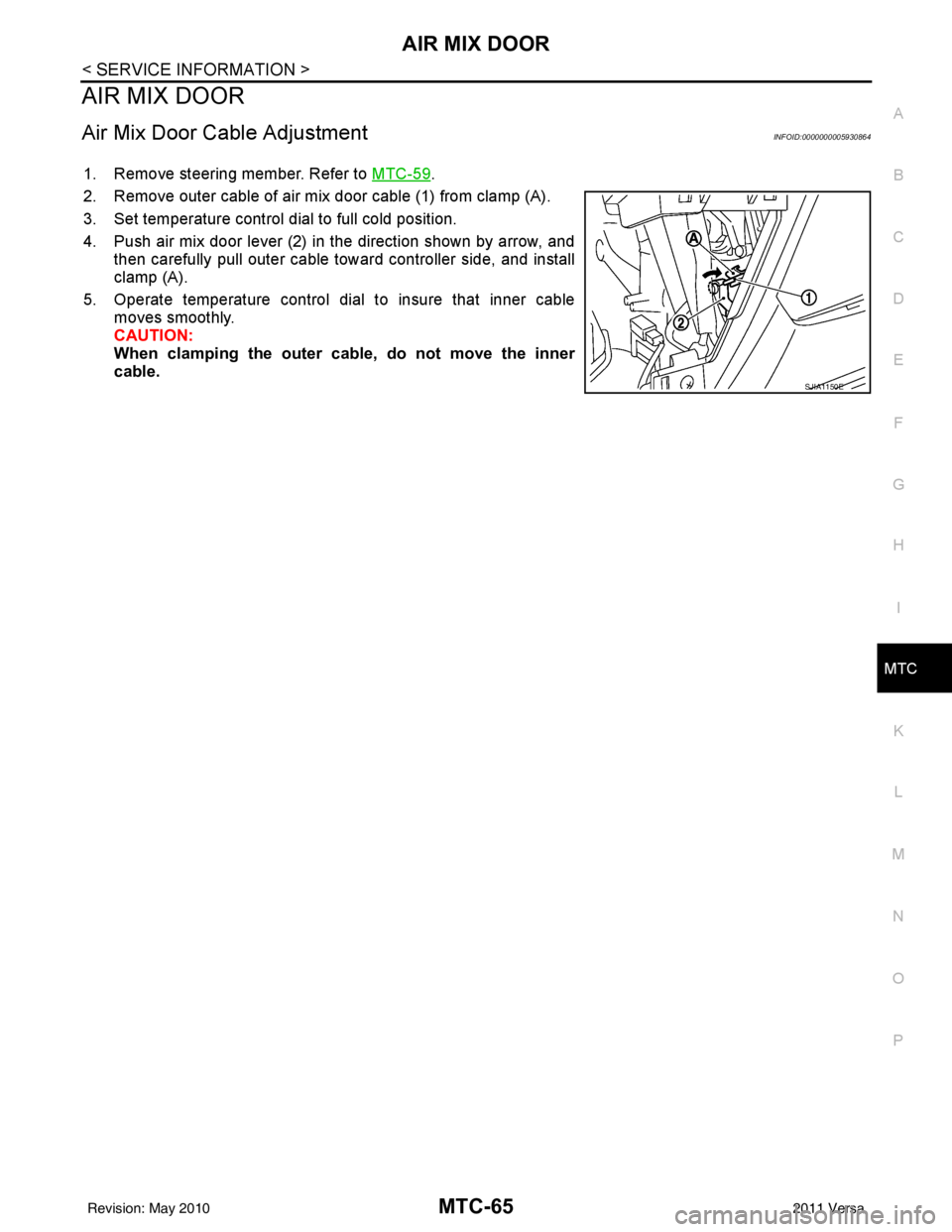
2. Remove outer cable of air mix door cable (1) from clamp (A).
3. Set temperature control dial to full cold position.
4. Push air mix door lever (2) in the direction shown by arrow, and then carefully pull outer cable toward controller side, and install
clamp (A).
5. Operate temperature control dial to insure that inner cable moves smoothly.
CAUTION:
When clamping the outer cab le, do not move the inner
cable.
SJIA1150E
Revision: May 2010 2011 Versa
Page 3382 of 3787
MTC-66
< SERVICE INFORMATION >
MODE DOOR
MODE DOOR
Mode Door Cable AdjustmentINFOID:0000000005930865
1. Remove glove box assembly and instrument lower cover (RH). Refer to IP-11.
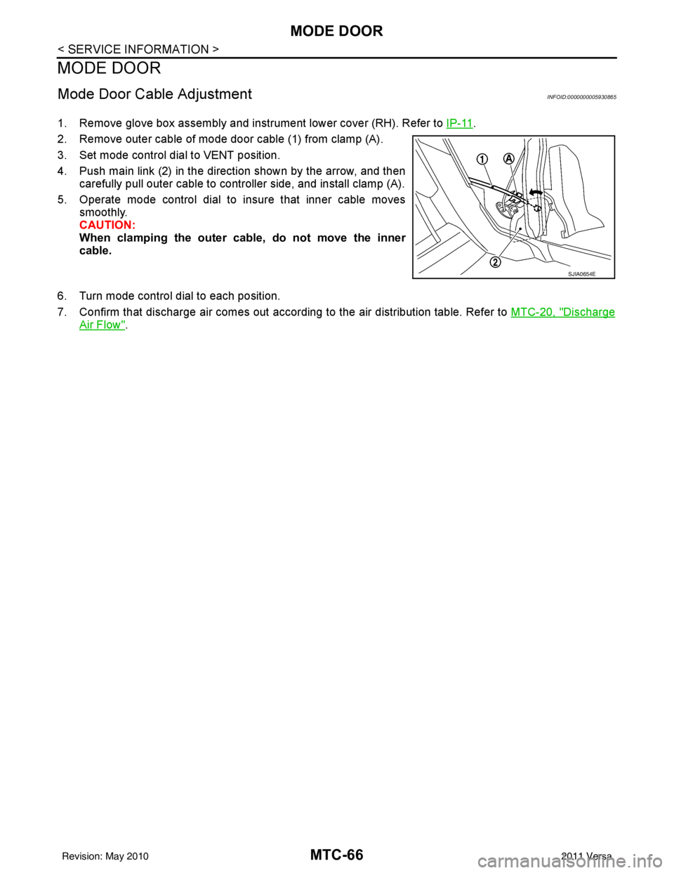
2. Remove outer cable of mode door cable (1) from clamp (A).
3. Set mode control dial to VENT position.
4. Push main link (2) in the direction shown by the arrow, and then carefully pull outer cable to controller side, and install clamp (A).
5. Operate mode control dial to insure that inner cable moves smoothly.
CAUTION:
When clamping the outer cable, do not move the inner
cable.
6. Turn mode control dial to each position.
7. Confirm that discharge air comes out according to the air distribution table. Refer to MTC-20, "
Discharge
Air Flow".
SJIA0654E
Revision: May 2010 2011 Versa
Page 3383 of 3787
BLOWER FAN RESISTORMTC-67
< SERVICE INFORMATION >
C
DE
F
G H
I
K L
M A
B
MTC
N
O P
BLOWER FAN RESISTOR
Removal and InstallationINFOID:0000000005930866
REMOVAL
1. Remove the instrument lower finisher. Refer to IP-11.
2. Remove the console side cover. Refer to IP-11
.
3. Remove the brake pedal assembly. Refer to BR-6
.
4. Disconnect the blower fan resistor connector.
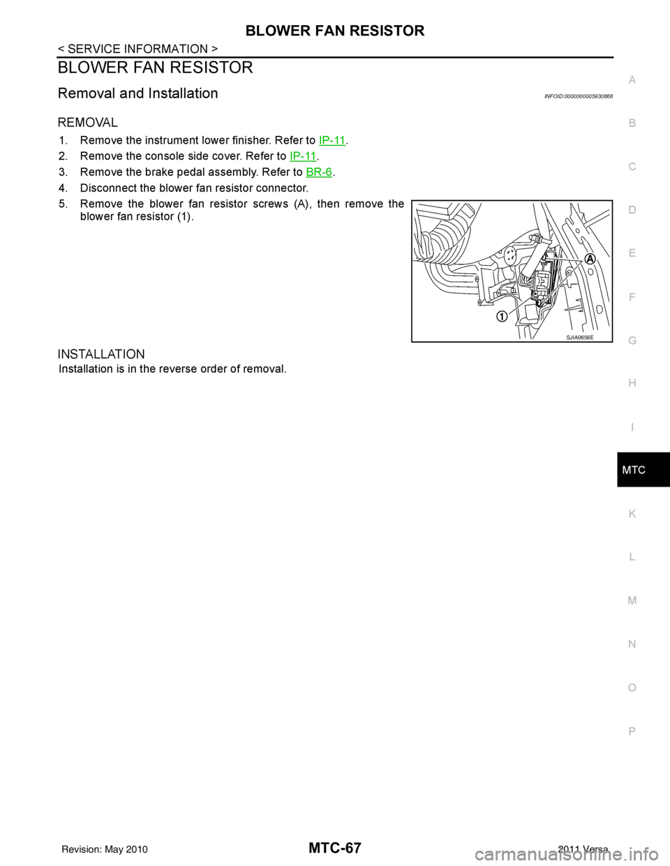
5. Remove the blower fan resistor screws (A), then remove the blower fan resistor (1).
INSTALLATION
Installation is in the reverse order of removal.
SJIA0656E
Revision: May 2010 2011 Versa
Page 3384 of 3787
MTC-68
< SERVICE INFORMATION >
HEATER CORE
HEATER CORE
Removal and InstallationINFOID:0000000005930867
REMOVAL
1. Remove the A/C unit assembly. Refer to MTC-59, "Removal and Installation".
2. Remove the foot duct (left). Refer to MTC-69, "
Removal and Installation".
3. Remove the heater pipe cover screw, then remove the heater pipe cover.
4. Remove the heater pipe clip screw, then remove the heater pipe clip.
5. Slide the heater core out of the A/C unit assembly.
INSTALLATION
Installation is in the reverse order of removal.
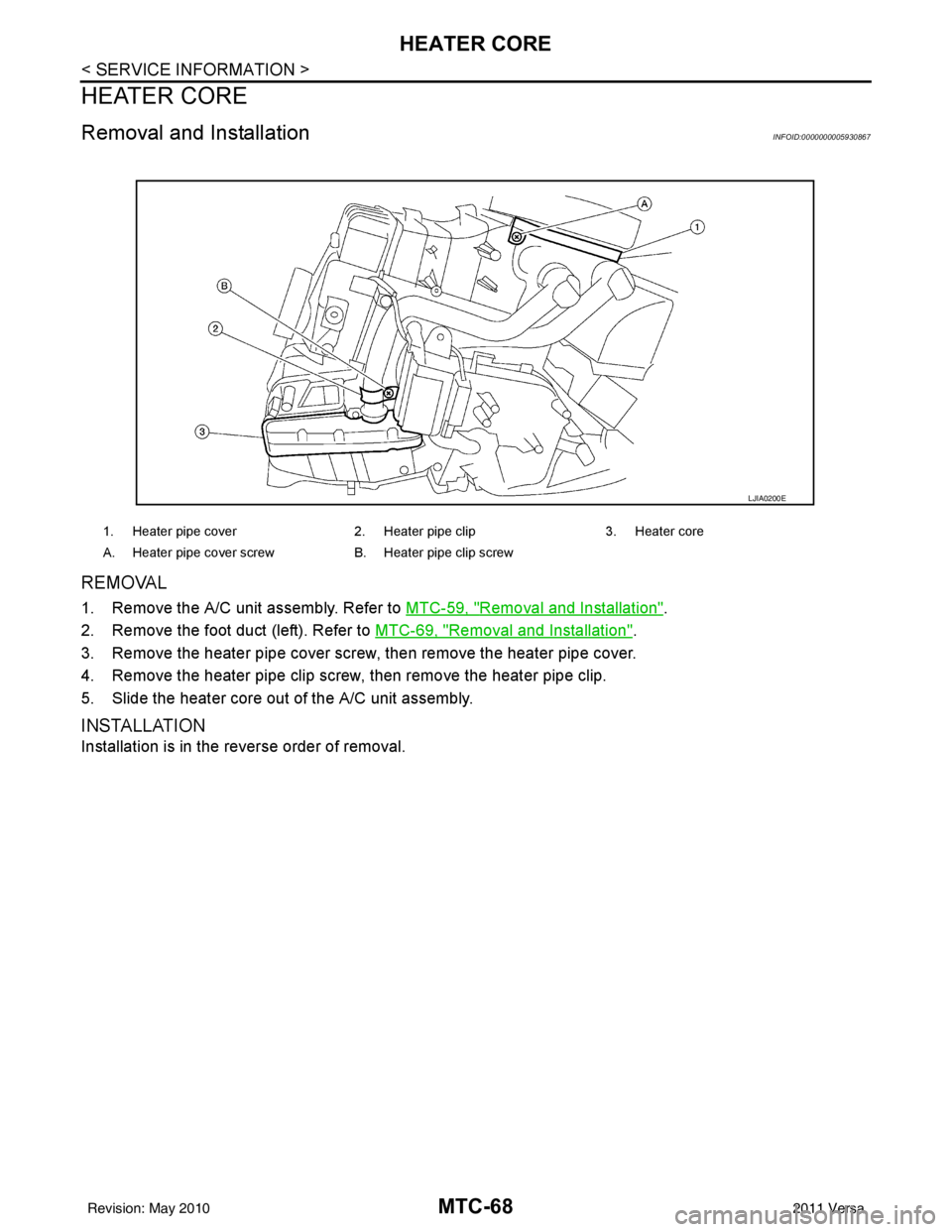
1. Heater pipe cover 2. Heater pipe clip3. Heater core
A. Heater pipe cover screw B. Heater pipe clip screw
LJIA0200E
Revision: May 2010 2011 Versa
Page 3385 of 3787
DUCTS AND GRILLESMTC-69
< SERVICE INFORMATION >
C
DE
F
G H
I
K L
M A
B
MTC
N
O P
DUCTS AND GRILLES
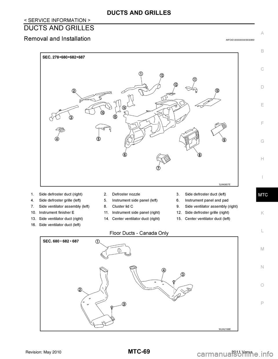
Removal and InstallationINFOID:0000000005930869
Floor Ducts - Canada Only
1. Side defroster duct (right) 2. Defroster nozzle3. Side defroster duct (left)
4. Side defroster grille (left) 5. Instrument side panel (left) 6. Instrument panel and pad
7. Side ventilator assembly (left) 8. Cluster lid C 9. Side ventilator assembly (right)
10. Instrument finisher E 11. Instrument side panel (right) 12. Side defroster grille (right)
13. Side ventilator duct (right) 14. Center ventilator duct (right) 15. Center ventilator duct (left)
16. Side ventilator duct (left)
SJIA0657E
WJIA2198E
Revision: May 2010 2011 Versa
Page 3386 of 3787
MTC-70
< SERVICE INFORMATION >
DUCTS AND GRILLES
CENTER VENTILATOR GRILLES
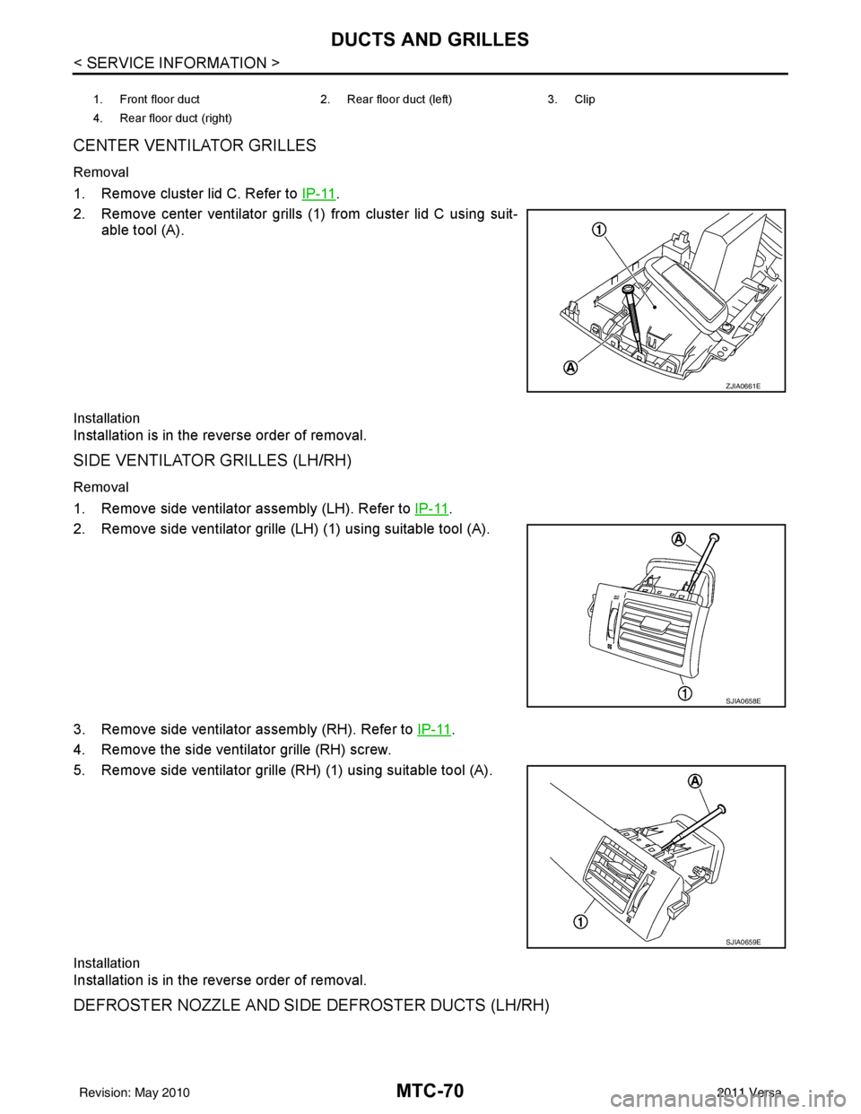
Removal
1. Remove cluster lid C. Refer to IP-11.
2. Remove center ventilator grills (1) from cluster lid C using suit- able tool (A).
Installation
Installation is in the reverse order of removal.
SIDE VENTILATOR GRILLES (LH/RH)
Removal
1. Remove side ventilator assembly (LH). Refer to IP-11.
2. Remove side ventilator grille (LH) (1) using suitable tool (A).
3. Remove side ventilator assembly (RH). Refer to IP-11
.
4. Remove the side ventilator grille (RH) screw.
5. Remove side ventilator grille (RH) (1) using suitable tool (A).
Installation
Installation is in the reverse order of removal.
DEFROSTER NOZZLE AND SIDE DEFROSTER DUCTS (LH/RH)
1. Front floor duct 2. Rear floor duct (left) 3. Clip
4. Rear floor duct (right)
ZJIA0661E
SJIA0658E
SJIA0659E
Revision: May 2010 2011 Versa
Page 3387 of 3787
DUCTS AND GRILLESMTC-71
< SERVICE INFORMATION >
C
DE
F
G H
I
K L
M A
B
MTC
N
O P
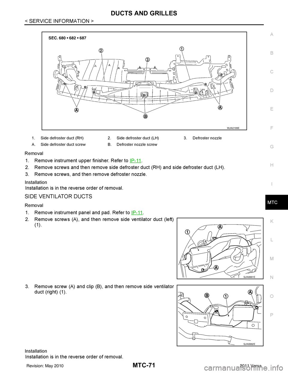
Removal
1. Remove instrument upper finisher. Refer to
IP-11.
2. Remove screws and then remove side defro ster duct (RH) and side defroster duct (LH).
3. Remove screws, and then remove defroster nozzle.
Installation
Installation is in the reverse order of removal.
SIDE VENTILATOR DUCTS
Removal
1. Remove instrument panel and pad. Refer to IP-11.
2. Remove screws (A), and then remove side ventilator duct (left) (1).
3. Remove screw (A) and clip (B), and then remove side ventilator duct (right) (1).
Installation
Installation is in the reverse order of removal.
1. Side defroster duct (RH) 2. Side defroster duct (LH)3. Defroster nozzle
A. Side defroster duct screw B. Defroster nozzle screw
WJIA2199E
SJIA0661E
SJIA0662E
Revision: May 2010 2011 Versa
Page 3388 of 3787
MTC-72
< SERVICE INFORMATION >
DUCTS AND GRILLES
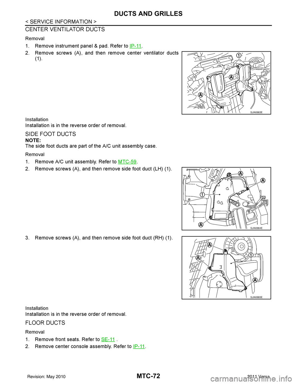
CENTER VENTILATOR DUCTS
Removal
1. Remove instrument panel & pad. Refer to IP-11.
2. Remove screws (A), and then remove center ventilator ducts (1).
Installation
Installation is in the reverse order of removal.
SIDE FOOT DUCTS
NOTE:
The side foot ducts are part of the A/C unit assembly case.
Removal
1. Remove A/C unit assembly. Refer to MTC-59.
2. Remove screws (A), and then remove side foot duct (LH) (1).
3. Remove screws (A), and then remove side foot duct (RH) (1).
Installation
Installation is in the reverse order of removal.
FLOOR DUCTS
Removal
1. Remove front seats. Refer to SE-11 .
2. Remove center console assembly. Refer to IP-11
.
SJIA0663E
SJIA0664E
SJIA0665E
Revision: May 2010 2011 Versa
Page 3389 of 3787
DUCTS AND GRILLESMTC-73
< SERVICE INFORMATION >
C
DE
F
G H
I
K L
M A
B
MTC
N
O P
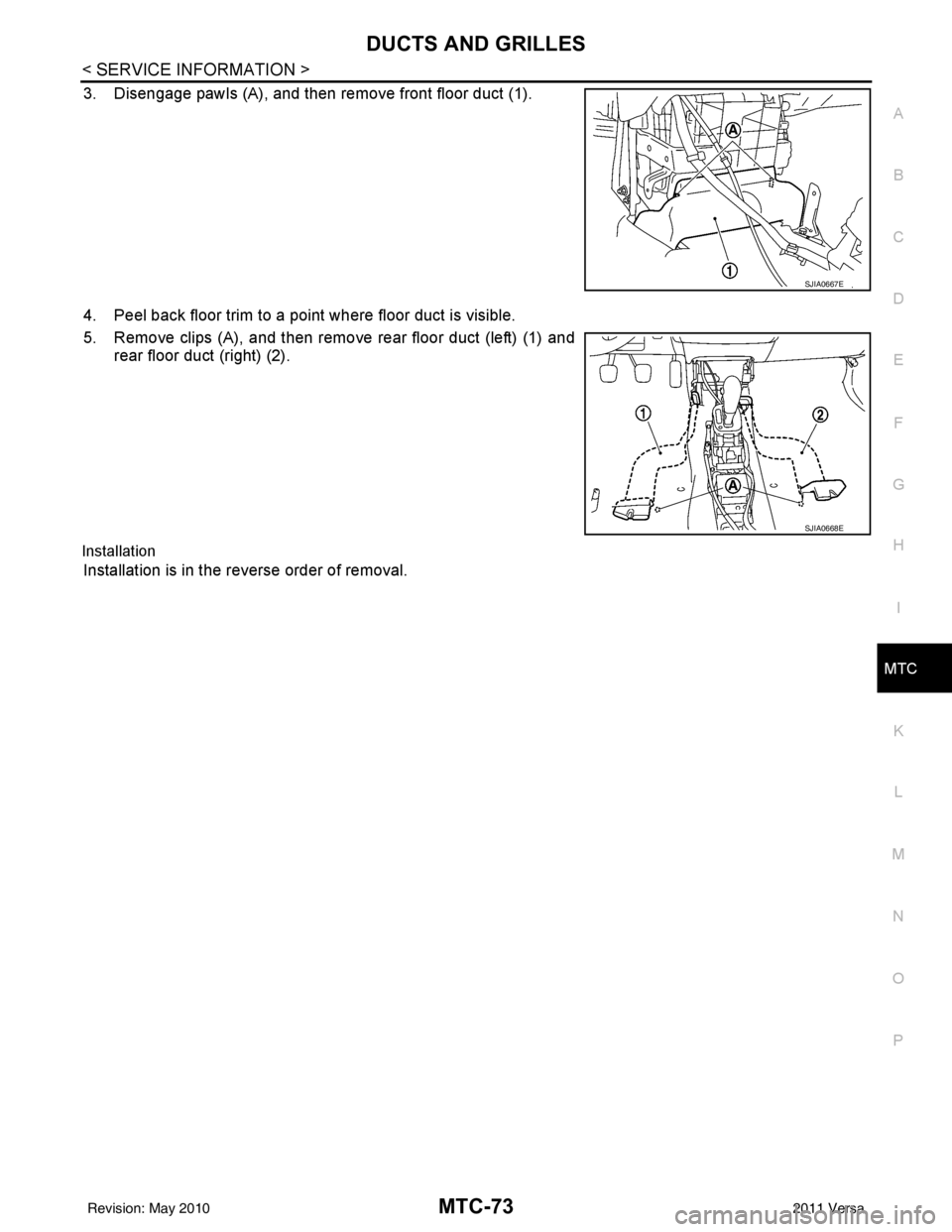
3. Disengage pawls (A), and then remove front floor duct (1).
4. Peel back floor trim to a point where floor duct is visible.
5. Remove clips (A), and then remove rear floor duct (left) (1) and rear floor duct (right) (2).
Installation
Installation is in the reverse order of removal.
SJIA0667E
SJIA0668E
Revision: May 2010 2011 Versa
Page 3390 of 3787
MTC-74
< SERVICE INFORMATION >
REFRIGERANT LINES
REFRIGERANT LINES
HFC-134a (R-134a) Service ProcedureINFOID:0000000005930870
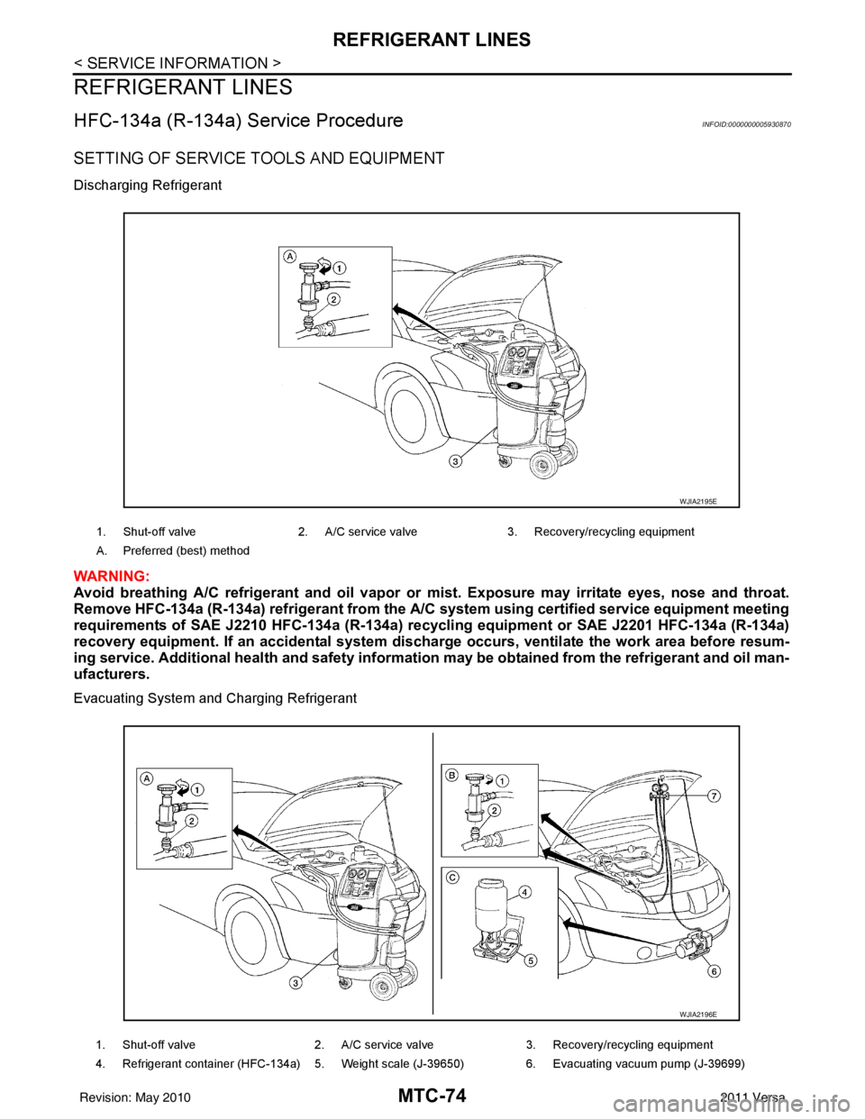
SETTING OF SERVICE TOOLS AND EQUIPMENT
Discharging Refrigerant
WARNING:
Avoid breathing A/C refrigerant and oil vapor or mist. Exposure may irritate eyes, nose and throat.
Remove HFC-134a (R-134a) refrigerant from the A/C system using certified service equipment meeting
requirements of SAE J2210 HFC-134a (R-134a) recycling equipment or SAE J2201 HFC-134a (R-134a)
recovery equipment. If an accident al system discharge occurs, ventilate the work area before resum-
ing service. Additional health and safety information may be obtained from the refrigerant and oil man-
ufacturers.
Evacuating System and Charging Refrigerant
1. Shut-off valve 2. A/C service valve 3. Recovery/recycling equipment
A. Preferred (best) method
WJIA2195E
1. Shut-off valve 2. A/C service valve3. Recovery/recycling equipment
4. Refrigerant container (HFC-134a) 5. Weight scale (J-39650) 6. Evacuating vacuum pump (J-39699)
WJIA2196E
Revision: May 2010 2011 Versa
Trending: fuse, radiator cap, manual radio set, headlights, charging, child restraint, CD player
