NISSAN LATIO 2011 Service Repair Manual
Manufacturer: NISSAN, Model Year: 2011, Model line: LATIO, Model: NISSAN LATIO 2011Pages: 3787, PDF Size: 78.35 MB
Page 3411 of 3787

REFRIGERANT LINESMTC-95
< SERVICE INFORMATION >
C
DE
F
G H
I
K L
M A
B
MTC
N
O P
6. Do not stop when one leak is found. Continue to check for additional leaks at all system components.
If no leaks are found, perform steps 7-10.
7. Start engine.
8. Set the heater A/C control as follows;
a. A/C switch: ON
b. Mode control dial position: VENT (Ventilation)
c. Intake door lever position: Recirculation
d. Max. cold temperature
e. Fan speed: High
9. Run engine at 1,500 rpm for at least 2 minutes.
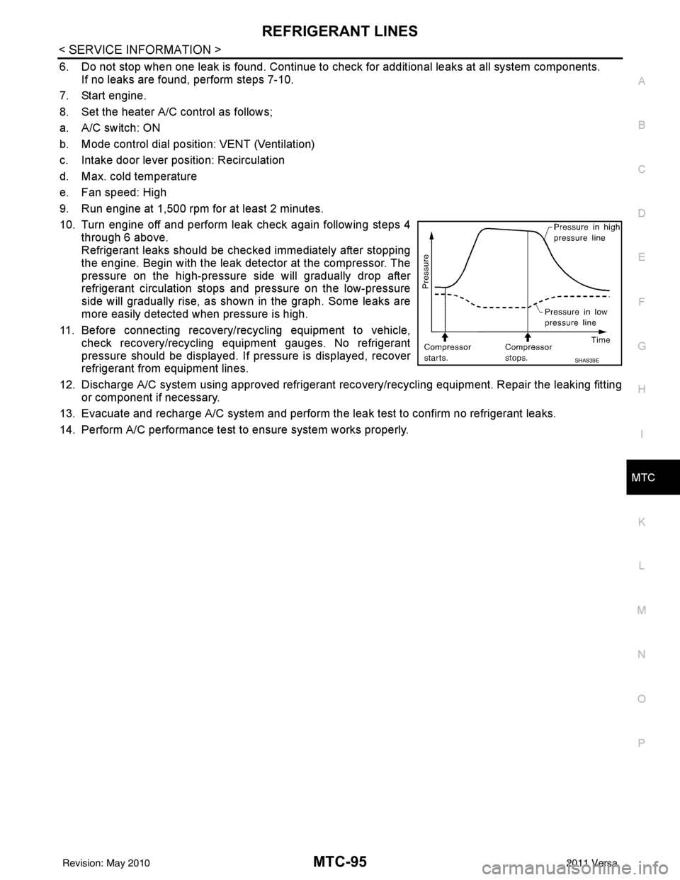
10. Turn engine off and perform leak check again following steps 4 through 6 above.
Refrigerant leaks should be chec ked immediately after stopping
the engine. Begin with the leak detector at the compressor. The
pressure on the high-pressure side will gradually drop after
refrigerant circulation stops and pressure on the low-pressure
side will gradually rise, as shown in the graph. Some leaks are
more easily detected when pressure is high.
11. Before connecting recovery/recycling equipment to vehicle, check recovery/recycling equipment gauges. No refrigerant
pressure should be displayed. If pressure is displayed, recover
refrigerant from equipment lines.
12. Discharge A/C system using approved refrigerant recovery/recycling equipment. Repair the leaking fitting or component if necessary.
13. Evacuate and recharge A/C system and perform the l eak test to confirm no refrigerant leaks.
14. Perform A/C performance test to ensure system works properly.
SHA839E
Revision: May 2010 2011 Versa
Page 3412 of 3787

MTC-96
< SERVICE INFORMATION >
SERVICE DATA AND SPECIFICATIONS (SDS)
SERVICE DATA AND SPECIFICATIONS (SDS)
CompressorINFOID:0000000005930888
OilINFOID:0000000005930889
RefrigerantINFOID:0000000005930890
ApplicationMR18DE - TYPE 1 and HR16DE MR18DE - TYPE 2
Compressor model Calsonic Kansei make CR-10Calsonic Kansei make CSV511
Type Vane rotaryVariable displacement swash plate
Displacement
cm
3 (in3) / revolution maximum
96 (5.86) 105 (6.41)
Cylinder bore × stroke
mm (in) maximum
— 34.8 (1.37) × 22.1 (0.87)
Direction of rotation Clockwise (viewed from drive end)
Drive belt Poly-V Ribbed 6-Groove
ApplicationMR18DE - TYPE 1 and HR16DE MR18DE - TYPE 2
Compressor model Calsonic Kansei make CR-10Calsonic Kansei make CSV511
Type NISSAN A/C System Oil Type RNISSAN A/C System Oil Type S
Capacity
m (US fl oz,
lmp fl oz) Total in system
120 (4.1, 4.2) 100 (3.4, 3.5)
Compressor (service
part) charging
amount Refer to
MTC-17, "
Maintenance of Oil Quanti-
ty in Compressor" . Refer to MTC-17, "
Maintenance of Oil
Quantity in Compressor" .
Ty p e
HFC-134a (R-134a)
Capacity
kg (lb) 0.45
± 0.05 (0.99 ± 0.11)
Revision: May 2010 2011 Versa
Page 3413 of 3787

PB-1
BRAKES
C
DE
G H
I
J
K L
M
SECTION PB
A
B
PB
N
O P
CONTENTS
PARKING BRAKE SYSTEM
SERVICE INFORMATION .. ..........................2
PRECAUTIONS .............................................. .....2
Precaution for Supplemental Restraint System
(SRS) "AIR BAG" and "SEAT BELT PRE-TEN-
SIONER" ............................................................. ......
2
Precaution Necessary for Steering Wheel Rota-
tion After Battery Disconnect ............................... ......
2
PREPARATION ...................................................4
Commercial Service Tool .................................... .....4
PARKING BRAKE CONTROL ...........................5
On-Vehicle Service ...................................................5
Component ...............................................................6
Removal and Installation ..........................................6
SERVICE DATA AND SPECIFICATIONS
(SDS) ..................................................................
8
Parking Brake Control ..............................................8
Revision: May 2010 2011 Versa
Page 3414 of 3787

PB-2
< SERVICE INFORMATION >
PRECAUTIONS
SERVICE INFORMATION
PRECAUTIONS
Precaution for Supplemental Restraint System (SRS) "AIR BAG" and "SEAT BELT
PRE-TENSIONER"
INFOID:0000000005929646
The Supplemental Restraint System such as “A IR BAG” and “SEAT BELT PRE-TENSIONER”, used along
with a front seat belt, helps to reduce the risk or severity of injury to the driver and front passenger for certain
types of collision. This system includes seat belt switch inputs and dual stage front air bag modules. The SRS
system uses the seat belt switches to determine the front air bag deployment, and may only deploy one front
air bag, depending on the severity of a collision and w hether the front occupants are belted or unbelted.
Information necessary to service the system safely is included in the SRS and SB section of this Service Man-
ual.
WARNING:
• To avoid rendering the SRS inopera tive, which could increase the risk of personal injury or death in
the event of a collision which would result in air bag inflation, all maintenance must be performed by
an authorized NISSAN/INFINITI dealer.
• Improper maintenance, including incorrect removal and installation of the SRS can lead to personal
injury caused by unintent ional activation of the system. For re moval of Spiral Cable and Air Bag
Module, see the SRS section.
• Do not use electrical test equipmen t on any circuit related to the SRS unless instructed to in this
Service Manual. SRS wiring harn esses can be identified by yellow and/or orange harnesses or har-
ness connectors.
PRECAUTIONS WHEN USING POWER TOOLS (AIR OR ELECTRIC) AND HAMMERS
WARNING:
• When working near the Airbag Diagnosis Sensor Unit or other Airbag System sensors with the Igni-
tion ON or engine running, DO NOT use air or electri c power tools or strike near the sensor(s) with a
hammer. Heavy vibration could activate the sensor( s) and deploy the air bag(s), possibly causing
serious injury.
• When using air or electric power tools or hammers , always switch the Ignition OFF, disconnect the
battery, and wait at least 3 minu tes before performing any service.
Precaution Necessary for Steering W heel Rotation After Battery Disconnect
INFOID:0000000005929647
NOTE:
• This Procedure is applied only to models with Intelligent Key system and NATS (NISSAN ANTI-THEFT SYS-
TEM).
• Remove and install all control units after disconnecting both battery cables with the ignition knob in the
″LOCK ″ position.
• Always use CONSULT-III to perform self-diagnosis as a part of each function inspection after finishing work.
If DTC is detected, perform trouble diagnosis according to self-diagnostic results.
For models equipped with the Intelligent Key system and NATS, an electrically controlled steering lock mech-
anism is adopted on the key cylinder.
For this reason, if the battery is disconnected or if the battery is discharged, the steering wheel will lock and
steering wheel rotation will become impossible.
If steering wheel rotation is required when battery pow er is interrupted, follow the procedure below before
starting the repair operation.
OPERATION PROCEDURE
1. Connect both battery cables. NOTE:
Supply power using jumper cables if battery is discharged.
2. Use the Intelligent Key or mechanical key to turn the ignition switch to the ″ACC ″ position. At this time, the
steering lock will be released.
3. Disconnect both battery cables. The steering lock will remain released and the steering wheel can be rotated.
4. Perform the necessary repair operation.
Revision: May 2010 2011 Versa
Page 3415 of 3787

PRECAUTIONSPB-3
< SERVICE INFORMATION >
C
DE
G H
I
J
K L
M A
B
PB
N
O P
5. When the repair work is completed, return the ignition switch to the ″LOCK ″ position before connecting
the battery cables. (At this time, the steering lock mechanism will engage.)
6. Perform a self-diagnosis check of al l control units using CONSULT-III.
Revision: May 2010 2011 Versa
Page 3416 of 3787

PB-4
< SERVICE INFORMATION >
PREPARATION
PREPARATION
Commercial Service ToolINFOID:0000000005929648
Tool nameDescription
Power tool Removing nuts, bolts and screws
PIIB1407E
Revision: May 2010 2011 Versa
Page 3417 of 3787

PARKING BRAKE CONTROLPB-5
< SERVICE INFORMATION >
C
DE
G H
I
J
K L
M A
B
PB
N
O P
PARKING BRAKE CONTROL
On-Vehicle ServiceINFOID:0000000005929649
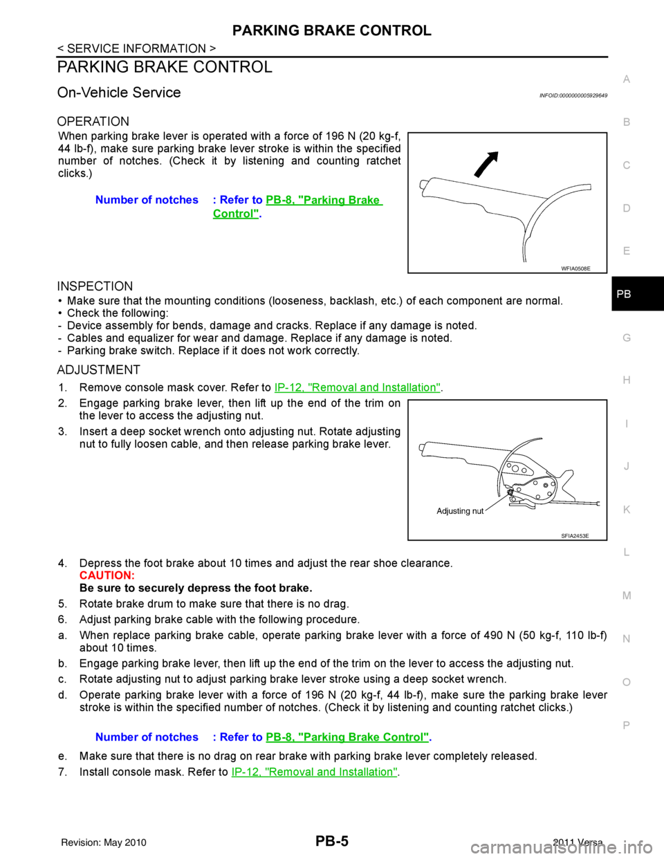
OPERATION
When parking brake lever is operated with a force of 196 N (20 kg-f,
44 lb-f), make sure parking brake le ver stroke is within the specified
number of notches. (Check it by listening and counting ratchet
clicks.)
INSPECTION
• Make sure that the mounting conditions (looseness, backlash, etc.) of each component are normal.
• Check the following:
- Device assembly for bends, damage and cracks. Replace if any damage is noted.
- Cables and equalizer for wear and damage. Replace if any damage is noted.
- Parking brake switch. Replace if it does not work correctly.
ADJUSTMENT
1. Remove console mask cover. Refer to IP-12, "Removal and Installation".
2. Engage parking brake lever, then lift up the end of the trim on the lever to access the adjusting nut.
3. Insert a deep socket wrench onto adjusting nut. Rotate adjusting nut to fully loosen cable, and then release parking brake lever.
4. Depress the foot brake about 10 ti mes and adjust the rear shoe clearance.
CAUTION:
Be sure to securely depress the foot brake.
5. Rotate brake drum to make sure that there is no drag.
6. Adjust parking brake cable with the following procedure.
a. When replace parking brake cable, operate parking br ake lever with a force of 490 N (50 kg-f, 110 lb-f)
about 10 times.
b. Engage parking brake lever, then lift up the end of the trim on the lever to access the adjusting nut.
c. Rotate adjusting nut to adjust parking brake lever stroke using a deep socket wrench.
d. Operate parking brake lever with a force of 196 N (20 kg-f, 44 lb-f), make sure the parking brake lever
stroke is within the specified number of notches. (Check it by listening and counting ratchet clicks.)
e. Make sure that there is no drag on rear brake with parking brake lever completely released.
7. Install console mask. Refer to IP-12, "
Removal and Installation".
Number of notches : Refer to
PB-8, "
Parking Brake
Control".
WFIA0508E
SFIA2453E
Number of notches : Refer to PB-8, "Parking Brake Control".
Revision: May 2010 2011 Versa
Page 3418 of 3787

PB-6
< SERVICE INFORMATION >
PARKING BRAKE CONTROL
Component
INFOID:0000000005929650
Removal and InstallationINFOID:0000000005929651
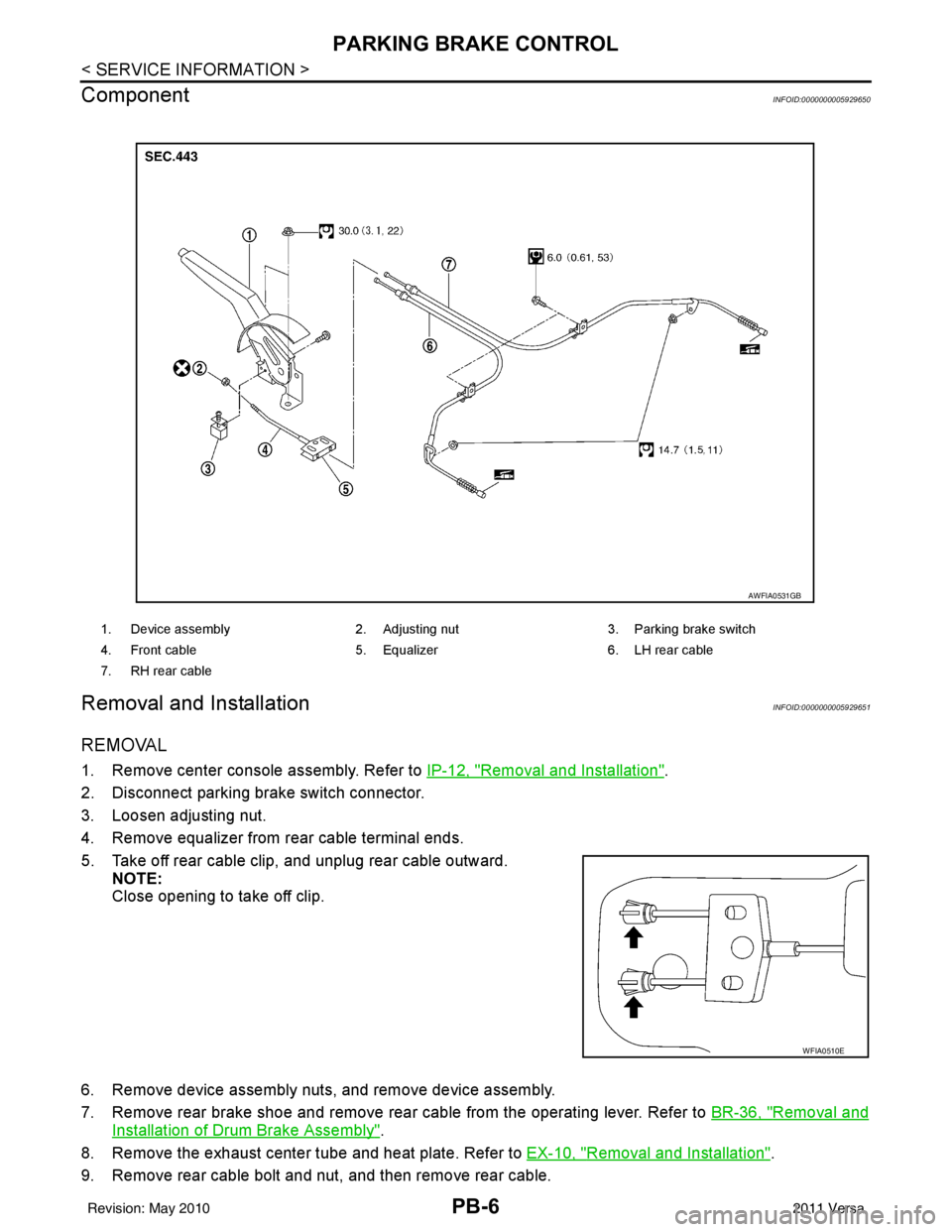
REMOVAL
1. Remove center console assembly. Refer to IP-12, "Removal and Installation".
2. Disconnect parking brake switch connector.
3. Loosen adjusting nut.
4. Remove equalizer from rear cable terminal ends.
5. Take off rear cable clip, and unplug rear cable outward. NOTE:
Close opening to take off clip.
6. Remove device assembly nuts, and remove device assembly.
7. Remove rear brake shoe and remove rear cable from the operating lever. Refer to BR-36, "
Removal and
Installation of Drum Brake Assembly".
8. Remove the exhaust center tube and heat plate. Refer to EX-10, "
Removal and Installation".
9. Remove rear cable bolt and nut, and then remove rear cable.
1. Device assembly 2. Adjusting nut3. Parking brake switch
4. Front cable 5. Equalizer6. LH rear cable
7. RH rear cable
AWFIA0531GB
WFIA0510E
Revision: May 2010 2011 Versa
Page 3419 of 3787

PARKING BRAKE CONTROLPB-7
< SERVICE INFORMATION >
C
DE
G H
I
J
K L
M A
B
PB
N
O P
10. Remove adjusting nut and discard. Remove the front cable from the device assembly.
CAUTION:
Discard the adjusting nut, do not reuse.
INSTALLATION
Installation is in the reverse order of removal.
• Adjust clearance of rear brake shoes. Refer to PB-5, "
On-Vehicle Service".
Revision: May 2010 2011 Versa
Page 3420 of 3787

PB-8
< SERVICE INFORMATION >
SERVICE DATA AND SPECIFICATIONS (SDS)
SERVICE DATA AND SPECIFICATIONS (SDS)
Parking Brake ControlINFOID:0000000005929652
Control typeHand lever
Number of notches [under a force of 196 N (20 kg-f, 44lb-f)] 8 − 9
Number of notches when brake warning lamp comes on 1
Revision: May 2010 2011 Versa