NISSAN LATIO 2011 Service Repair Manual
Manufacturer: NISSAN, Model Year: 2011, Model line: LATIO, Model: NISSAN LATIO 2011Pages: 3787, PDF Size: 78.35 MB
Page 3511 of 3787
POWER STEERING GEARPS-17
< SERVICE INFORMATION >
C
DE
F
H I
J
K L
M A
B
PS
N
O P
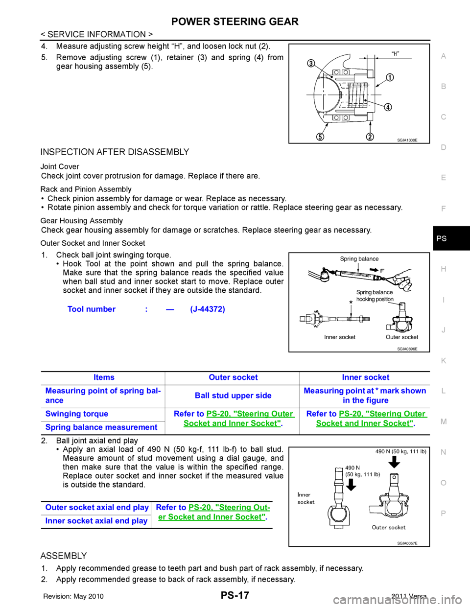
4. Measure adjusting screw height “H”, and loosen lock nut (2).
5. Remove adjusting screw (1), retainer (3) and spring (4) from gear housing assembly (5).
INSPECTION AFTER DISASSEMBLY
Joint Cover
Check joint cover protrusion for damage. Replace if there are.
Rack and Pinion Assembly
• Check pinion assembly for damage or wear. Replace as necessary.
• Rotate pinion assembly and check for torque variation or rattle. Replace steering gear as necessary.
Gear Housing Assembly
Check gear housing assembly for damage or scra tches. Replace steering gear as necessary.
Outer Socket and Inner Socket
1. Check ball joint swinging torque.
• Hook Tool at the point shown and pull the spring balance.
Make sure that the spring balance reads the specified value
when ball stud and inner socket start to move. Replace outer
socket and inner socket if they are outside the standard.
2. Ball joint axial end play • Apply an axial load of 490 N (50 kg-f, 111 lb-f) to ball stud.
Measure amount of stud movement using a dial gauge, and
then make sure that the value is within the specified range.
Replace outer socket and inner socket if the measured value
is outside the standard.
ASSEMBLY
1. Apply recommended grease to teeth part and bush part of rack assembly, if necessary.
2. Apply recommended grease to back of rack assembly, if necessary.
SGIA1300E
Tool number : — (J-44372)
SGIA0896E
ItemsOuter socket Inner socket
Measuring point of spring bal-
ance Ball stud upper sideMeasuring point at * mark shown
in the figure
Swinging torque Refer to PS-20, "
Steering Outer
Socket and Inner Socket".Refer to
PS-20, "
Steering Outer
Socket and Inner Socket".
Spring balance measurement
Outer socket axial end play Refer to PS-20, "
Steering Out-
er Socket and Inner Socket".
Inner socket axial end play
SGIA0057E
Revision: May 2010 2011 Versa
Page 3512 of 3787
PS-18
< SERVICE INFORMATION >
POWER STEERING GEAR
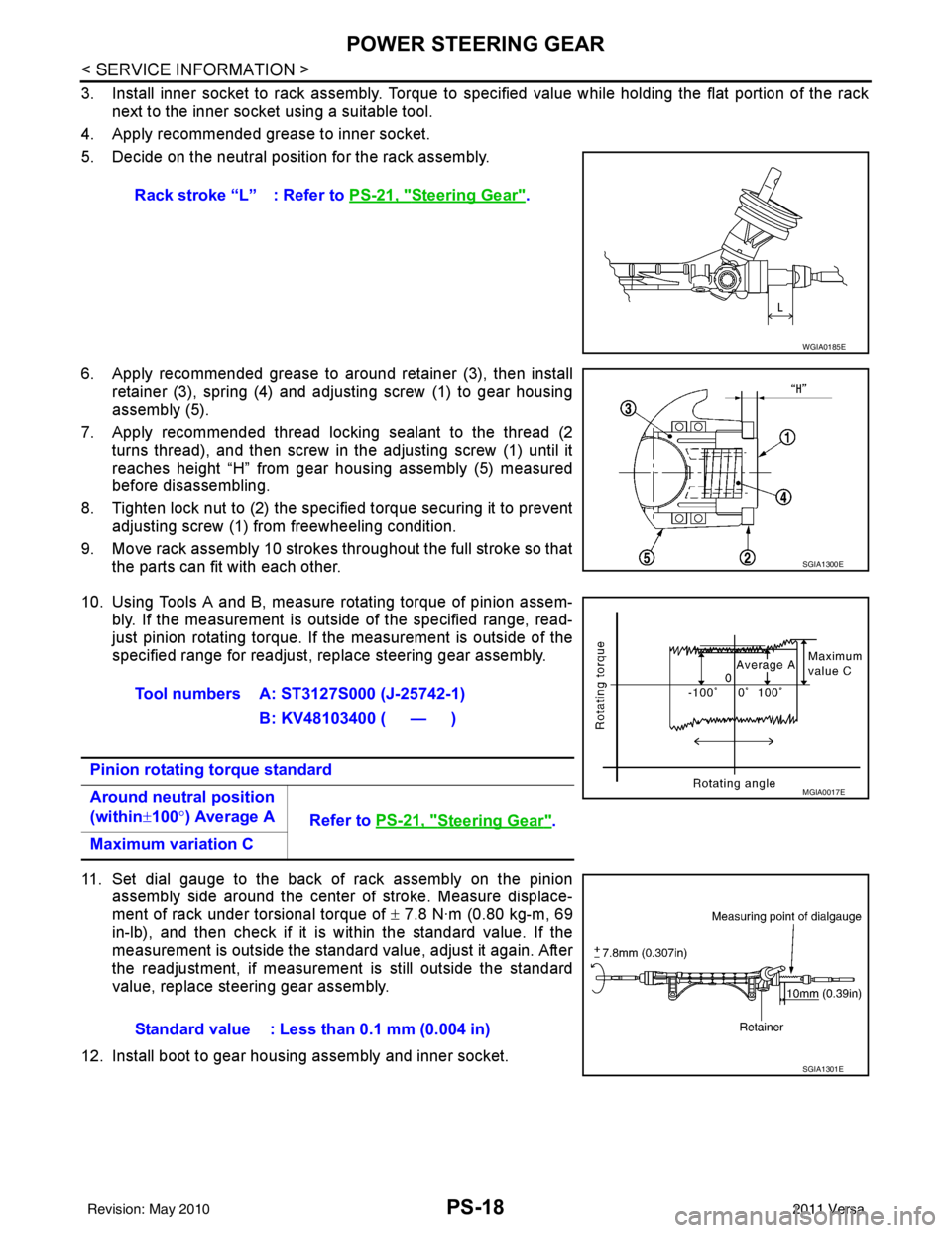
3. Install inner socket to rack assembly. Torque to specified value while holding the flat portion of the racknext to the inner socket using a suitable tool.
4. Apply recommended grease to inner socket.
5. Decide on the neutral position for the rack assembly.
6. Apply recommended grease to around retainer (3), then install retainer (3), spring (4) and adjusting screw (1) to gear housing
assembly (5).
7. Apply recommended thread locking sealant to the thread (2 turns thread), and then screw in the adjusting screw (1) until it
reaches height “H” from gear housing assembly (5) measured
before disassembling.
8. Tighten lock nut to (2) the specified torque securing it to prevent adjusting screw (1) from freewheeling condition.
9. Move rack assembly 10 strokes throughout the full stroke so that the parts can fit with each other.
10. Using Tools A and B, measure rotating torque of pinion assem- bly. If the measurement is out side of the specified range, read-
just pinion rotating torque. If the measurement is outside of the
specified range for readjust, replace steering gear assembly.
11. Set dial gauge to the back of rack assembly on the pinion assembly side around the center of stroke. Measure displace-
ment of rack under torsional torque of ± 7.8 N·m (0.80 kg-m, 69
in-lb), and then check if it is within the standard value. If the
measurement is outside the standard value, adjust it again. After
the readjustment, if measurement is still outside the standard
value, replace steering gear assembly.
12. Install boot to gear housing assembly and inner socket. Rack stroke “L” : Refer to
PS-21, "
Steering Gear".
WGIA0185E
SGIA1300E
Tool numbers A: ST3127S000 (J-25742-1)
B: KV48103400 ( — )
Pinion rotating torque standard
Around neutral position
(within ±100° ) Average A
Refer to PS-21, "
Steering Gear".
Maximum variation C
MGIA0017E
Standard value : Less than 0.1 mm (0.004 in)
SGIA1301E
Revision: May 2010 2011 Versa
Page 3513 of 3787
POWER STEERING GEARPS-19
< SERVICE INFORMATION >
C
DE
F
H I
J
K L
M A
B
PS
N
O P
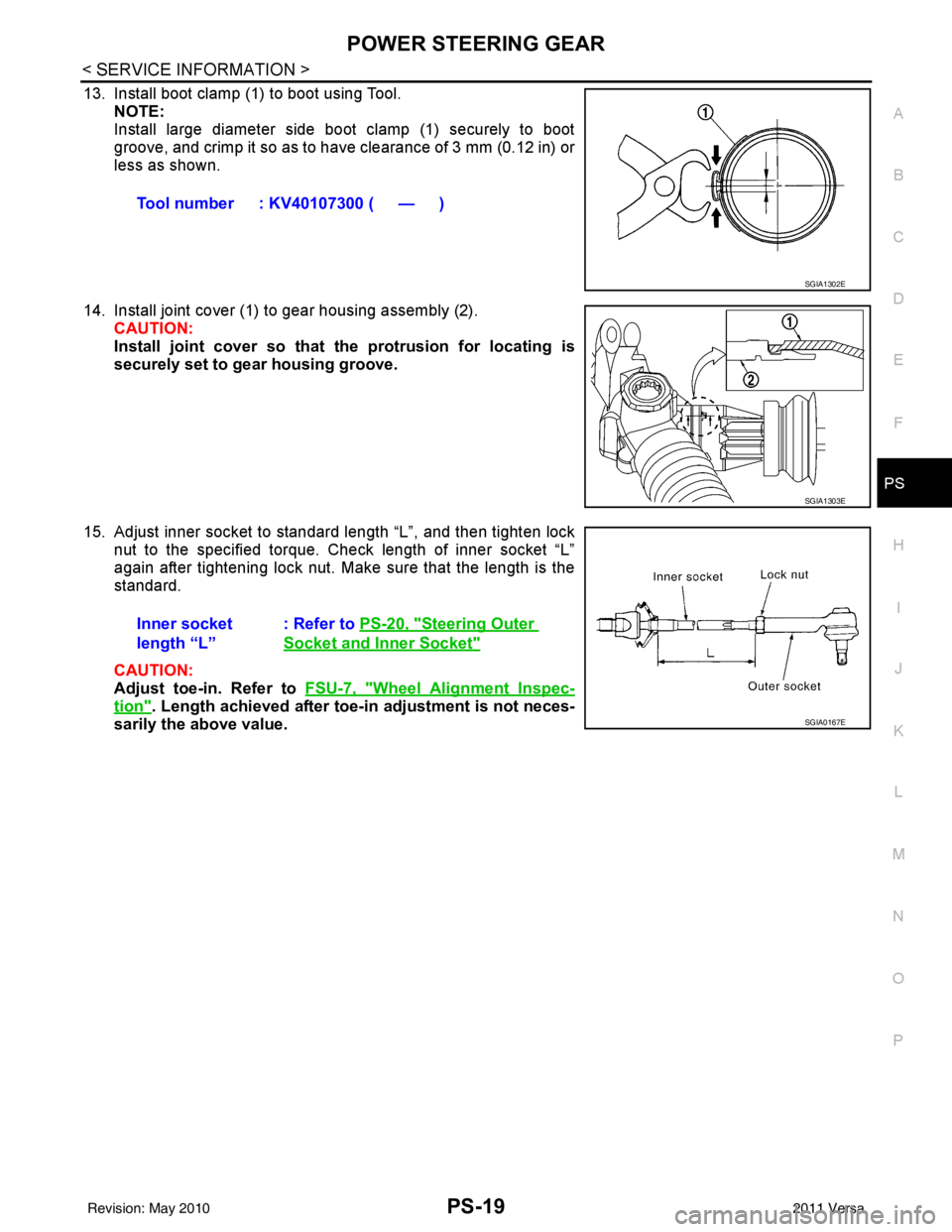
13. Install boot clamp (1) to boot using Tool. NOTE:
Install large diameter side boot clamp (1) securely to boot
groove, and crimp it so as to have clearance of 3 mm (0.12 in) or
less as shown.
14. Install joint cover (1) to gear housing assembly (2). CAUTION:
Install joint cover so that the protrusion for locating is
securely set to gear housing groove.
15. Adjust inner socket to standard length “L”, and then tighten lock nut to the specified torque. Check length of inner socket “L”
again after tightening lock nut. Make sure that the length is the
standard.
CAUTION:
Adjust toe-in. Refer to FSU-7, "
Wheel Alignment Inspec-
tion". Length achieved after toe-in adjustment is not neces-
sarily the above value. Tool number : KV40107300 ( — )
SGIA1302E
SGIA1303E
Inner socket
length “L”
: Refer to
PS-20, "Steering Outer
Socket and Inner Socket"
SGIA0167E
Revision: May 2010 2011 Versa
Page 3514 of 3787
PS-20
< SERVICE INFORMATION >
SERVICE DATA AND SPECIFICATIONS (SDS)
SERVICE DATA AND SPECIFICATIONS (SDS)
Steering WheelINFOID:0000000005929638
Steering AngleINFOID:0000000005929639
Steering ColumnINFOID:0000000005929640
Steering Outer Socket and Inner SocketINFOID:0000000005929641
Steering wheel axial end play0 mm (0 in)
Steering wheel play 0 - 35 mm (0 - 1.38 in)
Steering wheel turning force Less than 36 N (3.7 kg-f, 8.2 lb-f)
Inner wheel
Degree minute (Decimal degree)Minimum
35° 00 ′ (35.0 °)
Nominal 38° 00 ′ (38.0 °)
Maximum 39° 00 ′ (39.0 °)
Outer wheel
Degree minute (Decimal degree) 33
° 00 ′ (33.0 °)
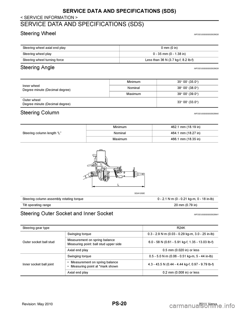
Steering column length “L” Minimum
462.1 mm (18.19 in)
Nominal 464.1 mm (18.27 in)
Maximum 466.1 mm (18.35 in)
Steering column assembly rotating torque 0 - 2.1 N·m (0 - 0.21 kg-m, 0 - 18 in-lb)
Tilt operating range 20 mm (0.79 in)
SGIA1293E
Steering gear type R24K
Outer socket ball stud Swinging torque
0.3 - 2.9 N·m (0.03 - 0.29 kg-m, 3.0 - 25 in-lb)
Measurement on spring balance
Measuring point: ball stud upper side 6.0 - 58 N (0.61 - 5.91 kg-f, 1.35 - 13.03 lb-f)
Axial end play 0.5 mm (0.020 in) or less
Inner socket ball joint Swinging torque
0.5 - 5.0 N·m (0.06 - 0.51 kg-m, 5 - 44 in-lb)
• Measurement on spring balance
• Measuring point at *mark shown 4.3 - 43.5 N (0.44 - 4.44 kg-f, 0.97 - 9.79 lb-f)
Axial end play 0.2 mm (0.008 in) or less
Revision: May 2010 2011 Versa
Page 3515 of 3787
SERVICE DATA AND SPECIFICATIONS (SDS)PS-21
< SERVICE INFORMATION >
C
DE
F
H I
J
K L
M A
B
PS
N
O P
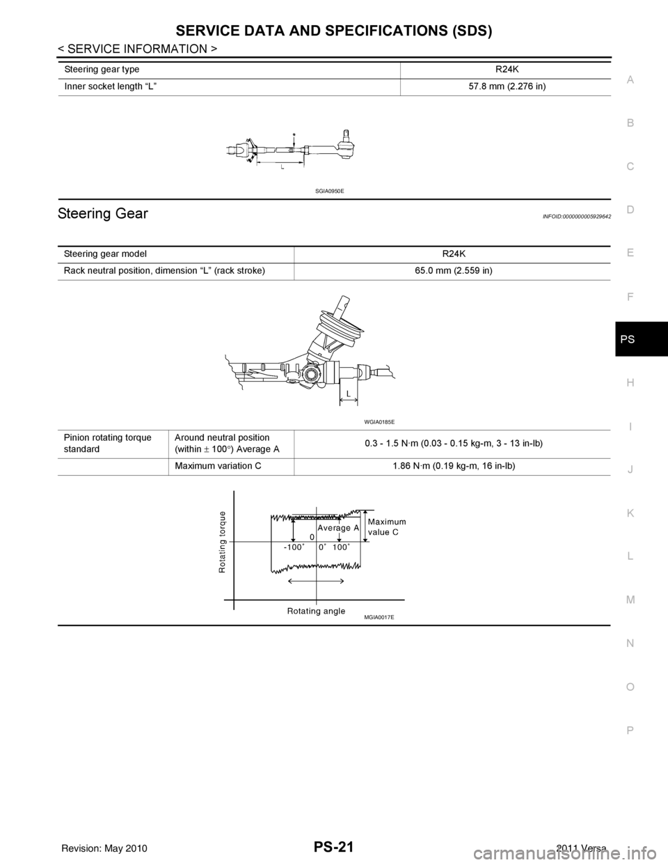
Steering GearINFOID:0000000005929642
Inner socket length “L” 57.8 mm (2.276 in)
Steering gear type
R24K
SGIA0950E
Steering gear modelR24K
Rack neutral position, dimension “L” (rack stroke) 65.0 mm (2.559 in)
Pinion rotating torque
standard Around neutral position
(within
± 100° ) Average A 0.3 - 1.5 N·m (0.03 - 0.
15 kg-m, 3 - 13 in-lb)
Maximum variation C 1.86 N·m (0.19 kg-m, 16 in-lb)
WGIA0185E
MGIA0017E
Revision: May 2010 2011 Versa
Page 3516 of 3787

RAX-1
DRIVELINE/AXLE
CEF
G H
I
J
K L
M
SECTION RAX
A
B
RAX
N
O P
CONTENTS
REAR AXLE
SERVICE INFORMATION .. ..........................2
PRECAUTIONS .............................................. .....2
Precaution for Supplemental Restraint System
(SRS) "AIR BAG" and "SEAT BELT PRE-TEN-
SIONER" ............................................................. ......
2
Precaution Necessary for Steering Wheel Rota-
tion After Battery Disconnect ............................... ......
2
PREPARATION ...................................................4
Commercial Service Tool .................................... ......4
NOISE, VIBRATION AND HARSHNESS
(NVH) TROUBLESHOOTING ............................
5
NVH Troubleshooting Chart ................................ .....5
WHEEL HUB ......................................................6
On-Vehicle Inspection and Service ..........................6
Removal and Installation ..........................................6
SERVICE DATA AND SPECIFICATIONS
(SDS) ..................................................................
8
Wheel Bearing ..........................................................8
Revision: May 2010 2011 Versa
Page 3517 of 3787

RAX-2
< SERVICE INFORMATION >
PRECAUTIONS
SERVICE INFORMATION
PRECAUTIONS
Precaution for Supplemental Restraint System (SRS) "AIR BAG" and "SEAT BELT
PRE-TENSIONER"
INFOID:0000000005928711
The Supplemental Restraint System such as “A IR BAG” and “SEAT BELT PRE-TENSIONER”, used along
with a front seat belt, helps to reduce the risk or severity of injury to the driver and front passenger for certain
types of collision. This system includes seat belt switch inputs and dual stage front air bag modules. The SRS
system uses the seat belt switches to determine the front air bag deployment, and may only deploy one front
air bag, depending on the severity of a collision and w hether the front occupants are belted or unbelted.
Information necessary to service the system safely is included in the SRS and SB section of this Service Man-
ual.
WARNING:
• To avoid rendering the SRS inopera tive, which could increase the risk of personal injury or death in
the event of a collision which would result in air bag inflation, all maintenance must be performed by
an authorized NISSAN/INFINITI dealer.
• Improper maintenance, including incorrect removal and installation of the SRS can lead to personal
injury caused by unintent ional activation of the system. For re moval of Spiral Cable and Air Bag
Module, see the SRS section.
• Do not use electrical test equipmen t on any circuit related to the SRS unless instructed to in this
Service Manual. SRS wiring harn esses can be identified by yellow and/or orange harnesses or har-
ness connectors.
PRECAUTIONS WHEN USING POWER TOOLS (AIR OR ELECTRIC) AND HAMMERS
WARNING:
• When working near the Airbag Diagnosis Sensor Unit or other Airbag System sensors with the Igni-
tion ON or engine running, DO NOT use air or electri c power tools or strike near the sensor(s) with a
hammer. Heavy vibration could activate the sensor( s) and deploy the air bag(s), possibly causing
serious injury.
• When using air or electric power tools or hammers , always switch the Ignition OFF, disconnect the
battery, and wait at least 3 minu tes before performing any service.
Precaution Necessary for Steering W heel Rotation After Battery Disconnect
INFOID:0000000005928712
NOTE:
• This Procedure is applied only to models with Intelligent Key system and NATS (NISSAN ANTI-THEFT SYS-
TEM).
• Remove and install all control units after disconnecting both battery cables with the ignition knob in the
″LOCK ″ position.
• Always use CONSULT-III to perform self-diagnosis as a part of each function inspection after finishing work.
If DTC is detected, perform trouble diagnosis according to self-diagnostic results.
For models equipped with the Intelligent Key system and NATS, an electrically controlled steering lock mech-
anism is adopted on the key cylinder.
For this reason, if the battery is disconnected or if the battery is discharged, the steering wheel will lock and
steering wheel rotation will become impossible.
If steering wheel rotation is required when battery pow er is interrupted, follow the procedure below before
starting the repair operation.
OPERATION PROCEDURE
1. Connect both battery cables. NOTE:
Supply power using jumper cables if battery is discharged.
2. Use the Intelligent Key or mechanical key to turn the ignition switch to the ″ACC ″ position. At this time, the
steering lock will be released.
3. Disconnect both battery cables. The steering lock will remain released and the steering wheel can be rotated.
4. Perform the necessary repair operation.
Revision: May 2010 2011 Versa
Page 3518 of 3787

PRECAUTIONSRAX-3
< SERVICE INFORMATION >
CEF
G H
I
J
K L
M A
B
RAX
N
O P
5. When the repair work is completed, return the ignition switch to the ″LOCK ″ position before connecting
the battery cables. (At this time, the steering lock mechanism will engage.)
6. Perform a self-diagnosis check of al l control units using CONSULT-III.
Revision: May 2010 2011 Versa
Page 3519 of 3787
RAX-4
< SERVICE INFORMATION >
PREPARATION
PREPARATION
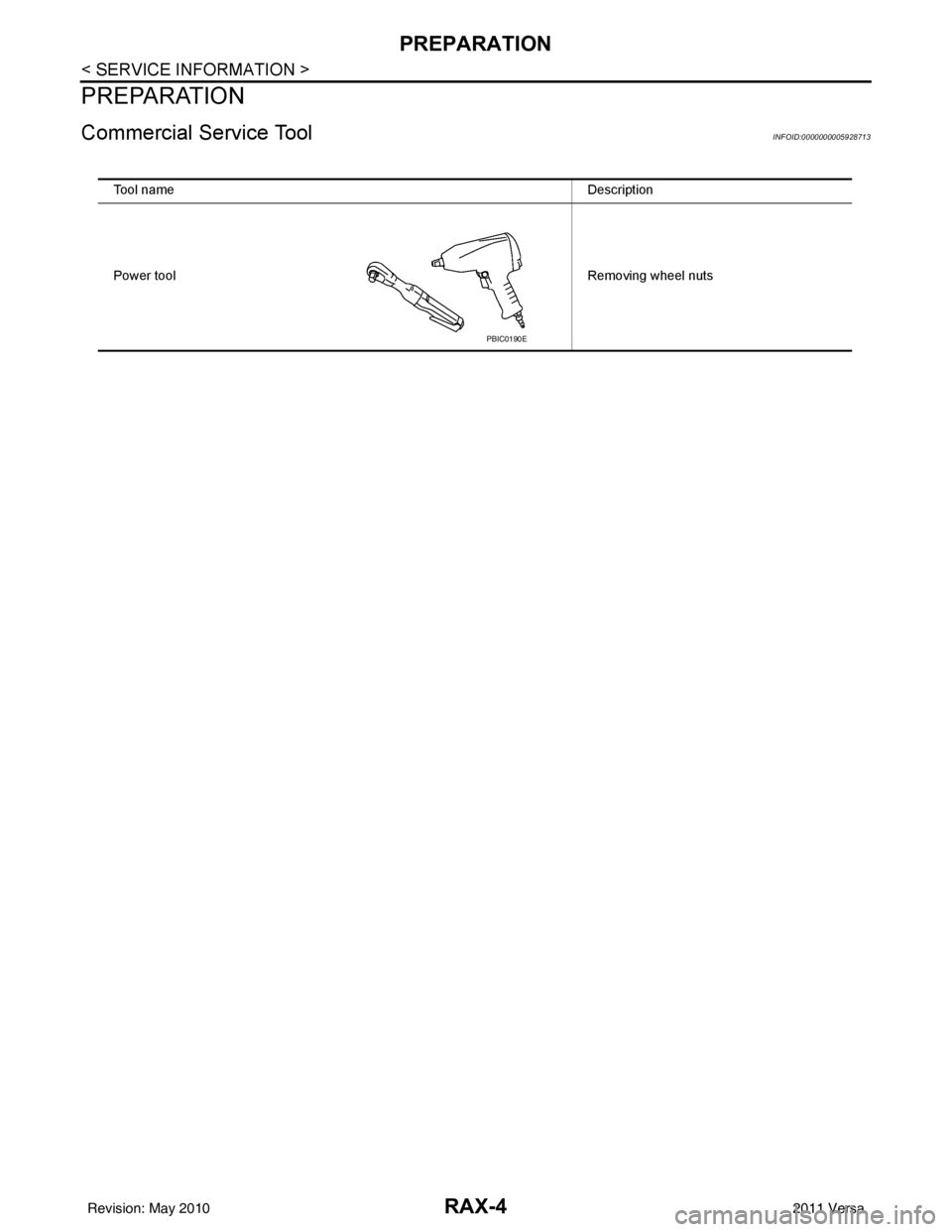
Commercial Service ToolINFOID:0000000005928713
Tool nameDescription
Power tool Removing wheel nuts
PBIC0190E
Revision: May 2010 2011 Versa
Page 3520 of 3787
NOISE, VIBRATION AND HARSHNESS (NVH) TROUBLESHOOTINGRAX-5
< SERVICE INFORMATION >
CEF
G H
I
J
K L
M A
B
RAX
N
O P
NOISE, VIBRATION AND HARSHN ESS (NVH) TROUBLESHOOTING
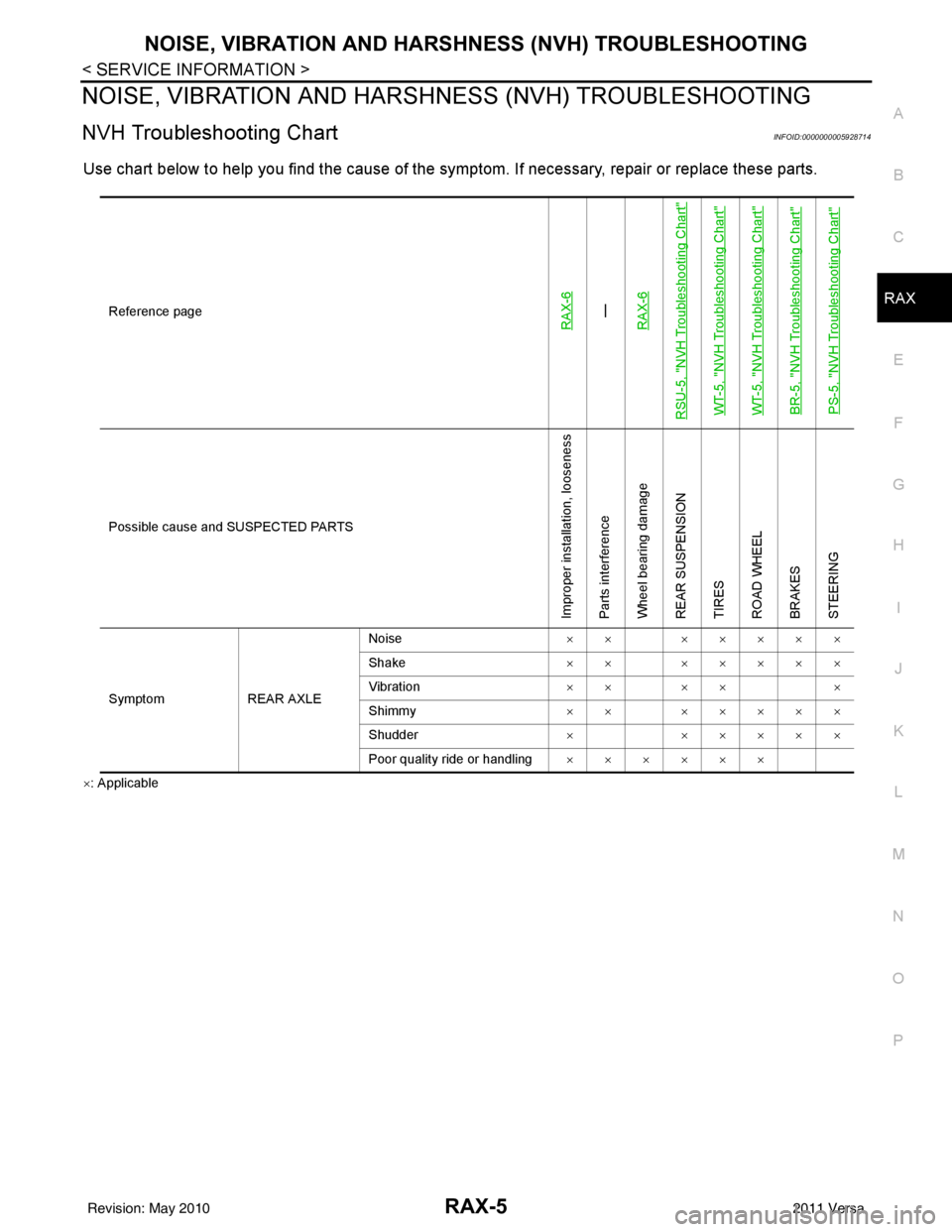
NVH Troubleshooting ChartINFOID:0000000005928714
Use chart below to help you find the cause of the symptom. If necessary, repair or replace these parts.
×: Applicable Reference page
RAX-6—
RAX-6
RSU-5, "
NVH Troubleshooting Chart
"
WT-5, "
NVH Troubleshooting Chart
"
WT-5, "
NVH Troubleshooting Chart
"
BR-5, "
NVH Troubleshooting Chart
"
PS-5, "
NVH Troubleshooting Chart
"
Possible cause and SUSPECTED PARTS
Improper installation, looseness
Parts interference
Wheel bearing damage
REAR SUSPENSION
TIRES
ROAD WHEEL
BRAKES
STEERING
Symptom REAR AXLENoise
×× ×××××
Shake ×× ×××××
Vibration ×× ×× ×
Shimmy ×× ×××××
Shudder ××××××
Poor quality ride or handling ××××××
Revision: May 2010 2011 Versa