headlamp NISSAN LATIO 2011 Service Owner's Guide
[x] Cancel search | Manufacturer: NISSAN, Model Year: 2011, Model line: LATIO, Model: NISSAN LATIO 2011Pages: 3787, PDF Size: 78.35 MB
Page 2858 of 3787
![NISSAN LATIO 2011 Service Owners Guide LAN-12
< SERVICE INFORMATION >[CAN FUNDAMENTAL]
TROUBLE DIAGNOSIS
NOTE:
• When data link connector branch line is open, transmission and reception of CAN communication signals
are not affected. Ther NISSAN LATIO 2011 Service Owners Guide LAN-12
< SERVICE INFORMATION >[CAN FUNDAMENTAL]
TROUBLE DIAGNOSIS
NOTE:
• When data link connector branch line is open, transmission and reception of CAN communication signals
are not affected. Ther](/img/5/57357/w960_57357-2857.png)
LAN-12
< SERVICE INFORMATION >[CAN FUNDAMENTAL]
TROUBLE DIAGNOSIS
NOTE:
• When data link connector branch line is open, transmission and reception of CAN communication signals
are not affected. Therefore, no symptoms occur. However, be sure to repair malfunctioning circuit.
• The model (all units on CAN communication system are Diag on CAN) cannot perform CAN diagnosis with
CONSULT-III if the following error occu rs. The error is judged by the symptom.
Example: Main Line Between Data Link Connector and ABS Actuator and Electric Un it (Control Unit) Open Circuit
Unit name Symptom
ECM
Normal operation.
BCM
EPS control unit
Combination meter
ABS actuator and electric unit (control unit)
TCM
IPDM E/R
Error Difference of symptom
Data link connector branch line open circuit Normal operation.
CAN-H, CAN-L harness short-circuit Most of the units which are connected to the CAN communication
system enter fail-safe mode or are deactivated.
SKIB8740E
Unit name
Symptom
ECM Engine torque limiting is affected, and shift harshness increases.
BCM • Reverse warning chime does not sound.
• The front wiper moves under continuous operation mode even though the front wip-
er switch being in the intermittent position.
EPS control unit The steering effort increases.
Combination meter • The shift position indicator and OD OFF indicator turn OFF.
• The speedometer is inoperative.
• The odo/trip meter stops.
ABS actuator and electric unit (control unit) Normal operation.
TCM No impact on operation.
IPDM E/R When the ignition switch is ON,
• The headlamps (Lo) turn ON.
• The cooling fan continues to rotate.
Revision: May 2010
2011 Versa
Page 2859 of 3787
![NISSAN LATIO 2011 Service Owners Guide TROUBLE DIAGNOSISLAN-13
< SERVICE INFORMATION > [CAN FUNDAMENTAL]
C
D
E
F
G H
I
J
L
M A
B
LAN
N
O P
Example: CAN-H, CAN-L Harness Short Circuit
CAN Diagnosis with CONSULT-IIIINFOID:0000000005928521
CA NISSAN LATIO 2011 Service Owners Guide TROUBLE DIAGNOSISLAN-13
< SERVICE INFORMATION > [CAN FUNDAMENTAL]
C
D
E
F
G H
I
J
L
M A
B
LAN
N
O P
Example: CAN-H, CAN-L Harness Short Circuit
CAN Diagnosis with CONSULT-IIIINFOID:0000000005928521
CA](/img/5/57357/w960_57357-2858.png)
TROUBLE DIAGNOSISLAN-13
< SERVICE INFORMATION > [CAN FUNDAMENTAL]
C
D
E
F
G H
I
J
L
M A
B
LAN
N
O P
Example: CAN-H, CAN-L Harness Short Circuit
CAN Diagnosis with CONSULT-IIIINFOID:0000000005928521
CAN diagnosis on CONSULT-III extracts the root
cause by receiving the following information.
• Response to the system call
• Control unit diagnosis information
• Self-diagnosis
• CAN diagnostic support monitor
SKIB8741E
Unit name Symptom
ECM • Engine torque limiting is affected, and shift harshness increases.
• Engine speed drops.
BCM • Reverse warning chime does not sound.
• The front wiper moves under continuous operation mode even though the front
wiper switch being in the intermittent position.
• The room lamp does not turn ON.
• The engine does not start (if an error or malfunction occurs while turning the igni- tion switch OFF.)
• The steering lock does not release (if an error or malfunction occurs while turning the ignition switch OFF.)
EPS control unit The steering effort increases.
Combination meter • The tachometer and the speedometer do not move.
• Warning lamps turn ON.
• Indicator lamps do not turn ON.
ABS actuator and electric unit (control unit) Normal operation.
TCM No impact on operation.
IPDM E/R When the ignition switch is ON,
• The headlamps (Lo) turn ON.
• The cooling fan continues to rotate.
Revision: May 2010
2011 Versa
Page 3033 of 3787

LT-1
ELECTRICAL
C
DE
F
G H
I
J
L
M
SECTION LT
A
B
LT
N
O P
CONTENTS
LIGHTING SYSTEM
SERVICE INFORMATION .. ..........................3
PRECAUTIONS .............................................. .....3
Precaution for Supplemental Restraint System
(SRS) "AIR BAG" and "SEAT BELT PRE-TEN-
SIONER" ............................................................. ......
3
Precaution Necessary for Steering Wheel Rota-
tion After Battery Disconnect ............................... ......
3
HEADLAMP (FOR USA) .....................................5
Component Parts and Harness Connector Loca-
tion ...................................................................... ......
5
System Description ...................................................5
CAN COMMUNICATION SYSTEM DESCRIP-
TION .................................................................... ......
6
Schematic .................................................................7
Wiring Diagram .........................................................8
Terminal and Reference Value for BCM .................11
Terminal and Reference Value for IPDM E/R .........11
How to Perform Trouble Diagnosis .........................12
Preliminary Check ...................................................12
CONSULT-III Function (BCM) .................................12
CONSULT-III Function (IPDM E/R) .........................13
Headlamp High Beam Does Not Illuminate (Both
Sides) .................................................................. ....
15
Headlamp High Beam Does Not Illuminate (One
Side) .................................................................... ....
17
High Beam Indicator Lamp Does Not Illuminate .....18
Headlamp Low Beam Does Not Illuminate (Both
Sides) .................................................................. ....
19
Headlamp Low Beam Does Not Illuminate (One
Side) .................................................................... ....
21
Headlamps Do Not Turn OFF .................................22
Aiming Adjustment ..................................................23
Bulb Replacement ...................................................24
Removal and Installation .........................................25
Disassembly and Assembly ................................ ....25
HEADLAMP (FOR CANADA) - DAYTIME
LIGHT SYSTEM - ........................................... ....
27
Component Parts and Harness Connector Loca-
tion ....................................................................... ....
27
System Description ..................................................27
CAN Communication System Description ...............29
Schematic ................................................................30
Wiring Diagram - DTRL - .........................................31
Terminal and Reference Value for BCM ..................34
Terminal and Reference Value for IPDM E/R ...... ....34
How to Perform Trouble Diagnosis ..........................35
Preliminary Check ...................................................35
CONSULT-III Function (BCM) .................................35
CONSULT-III Function (IPDM E/R) ..................... ....35
Daytime Light Control Does Not Operate Properly
(High Beam Headlamps Operate Properly) .............
35
Aiming Adjustment ...................................................37
Bulb Replacement ...................................................38
Removal and Installation .........................................39
Disassembly and Assembly .....................................39
FRONT FOG LAMP ..........................................41
Component Parts and Harness Connector Loca-
tion ...........................................................................
41
System Description ..................................................41
CAN Communication System Description ...............42
Wiring Diagram - F/FOG - .......................................43
Terminal and Reference Value for BCM ..................44
Terminal and Reference Value for IPDM E/R ...... ....44
How to Proceed with Trouble Diagnosis ..................45
Preliminary Check ............................................... ....45
CONSULT-III Function (BCM) .................................45
CONSULT-III Function (IPDM E/R) ..................... ....45
Front Fog lamps Do Not Illuminate (Both Sides) .....45
Front Fog Lamp Does Not Illuminate (One Side) ....47
Aiming Adjustment ...................................................48
Bulb Replacement ...................................................49
Removal and Installation .........................................49
TURN SIGNAL AND HAZARD WARNING
LAMPS ..............................................................
50
Component Parts and Harness Connector Loca-
tion ...........................................................................
50
Revision: May 2010 2011 Versa
Page 3034 of 3787

LT-2
System Description .................................................50
CAN Communication System Description ..............52
Schematic ............................................................ ...53
Wiring Diagram - TURN - ........................................54
Terminal and Reference Value for BCM .................57
How to Proceed with Trouble Diagnosis .................57
Preliminary Check ..................................................58
CONSULT-III Function (BCM) ................................58
Turn Signals Do Not Operate .................................58
Front Turn Signal Lamp Does Not Operate ............58
Rear Turn Signal Lamp Does Not Operate ............59
Hazard Warning Lamp Does Not Operate But
Turn Signal Lamp Operates ...................................
60
Turn Signal Indicator Lamp Does Not Operate ......61
Bulb Replacement for Front Turn Signal Lamp ......61
Bulb Replacement for Rear Turn Signal Lamp .......61
Removal and Installation of Front Turn Signal
Lamp .......................................................................
61
Removal and Installation of Rear Turn Signal
Lamp .......................................................................
61
LIGHTING AND TURN SIGNAL SWITCH .........62
Removal and Installation ..................................... ...62
HAZARD SWITCH .............................................63
Removal and Installation ..................................... ...63
COMBINATION SWITCH ..................................64
Wiring Diagram - COMBSW - .............................. ...64
Combination Switch Reading Function ...................64
Terminal and Reference Value for BCM .................65
CONSULT-III Function (BCM) ................................65
Combination Switch Inspection ..............................65
Removal and Installation ..................................... ...67
STOP LAMP ......................................................68
Wiring Diagram - STOP/L .................................... ...68
Wiring Diagram - STOP/L .......................................69
Bulb Replacement (High-Mounted Stop Lamp) ......69
Bulb Replacement (Rear Combination Lamp) ........70
Removal and Installation (High-Mounted Stop
Lamp) .....................................................................
70
Removal and Installation (Rear Combination
Lamp) .................................................................. ...
71
BACK-UP LAMP ................................................72
Wiring Diagram - BACK/L - .................................. ...72
Bulb Replacement ..................................................72
Removal and Installation ........................................73
PARKING, LICENSE PLATE AND TAIL
LAMPS ...............................................................
74
Component Parts and Harness Connector Loca-
tion ....................................................................... ...
74
System Description .................................................74
CAN Communication System Description ........... ...75
Schematic ...............................................................76
Wiring Diagram - TAIL/L - .......................................77
Terminal and Reference Value for BCM .............. ...80
Terminal and Reference Value for IPDM E/R .........80
How to Proceed with Trouble Diagnosis .................81
Preliminary Check ...................................................81
CONSULT-III Function (BCM) ............................. ...81
CONSULT-III Function (IPDM E/R) ........................81
Parking, License Plate and Tail Lamps Do Not Il-
luminate ..................................................................
81
Parking, License Plate and Tail Lamps Do Not
Turn OFF (After Approx. 10 Minutes) .....................
84
Bulb Replacement ................................................ ...84
Removal and Installation .........................................85
REAR COMBINATION LAMP ........................ ...87
Component .......................................................... ...87
Bulb Replacement ...................................................87
Removal and Installation .........................................88
Disassembly and Assembly ................................. ...88
INTERIOR LAMP ...............................................90
Map Lamp ............................................................ ...90
Luggage Room Lamp, Hatch Back .........................90
Trunk Room Lamp, Sedan ......................................91
Vanity Mirror Lamp ..................................................91
INTERIOR ROOM LAMP ...................................93
Component Parts and Harness Connector Loca-
tion ....................................................................... ...
93
System Description .................................................93
Schematic ...............................................................97
Wiring Diagram - INT/L - .........................................98
Terminal and Reference Value for BCM ...............102
How to Proceed with Trouble Diagnosis ...............102
Preliminary Check .................................................103
CONSULT-III Function (BCM) ............................. .103
Interior Room Lamp Control Does Not Operate
(With Map Lamp) ..................................................
104
Interior Room Lamp Control Does Not Operate
(Without Map Lamp) .............................................
106
Bulb Replacement .................................................107
Removal and Installation .......................................108
ILLUMINATION .............................................. ..109
System Description .............................................. .109
CAN Communication System Description ............110
Schematic .............................................................111
Wiring Diagram - ILL - ...........................................112
BULB SPECIFICATIONS ............................... ..116
Headlamp ............................................................. .116
Exterior Lamp ........................................................116
Interior Lamp/Illumination .....................................
Revision: May 2010 2011 Versa
Page 3037 of 3787
HEADLAMP (FOR USA)LT-5
< SERVICE INFORMATION >
C
DE
F
G H
I
J
L
M A
B
LT
N
O P
HEADLAMP (FOR USA)
Component Parts and Har ness Connector LocationINFOID:0000000005929028
System DescriptionINFOID:0000000005929029
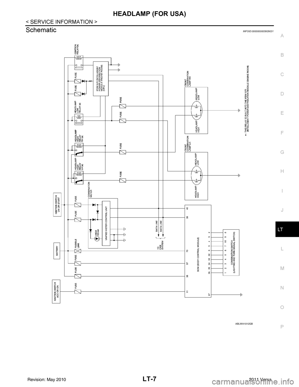
Headlamp operation is controlled by the BCM (body c ontrol module) based on inputs from the combination
switch (lighting and turn signal switch). When the light ing switch is placed in the 2ND position, the BCM
receives an input signal requesting the headlamps (and tail lamps) illuminate. The BCM sends a signal, via the
CAN communication lines, to the IPDM E/R (intelligent power distribution module engine room) requesting the
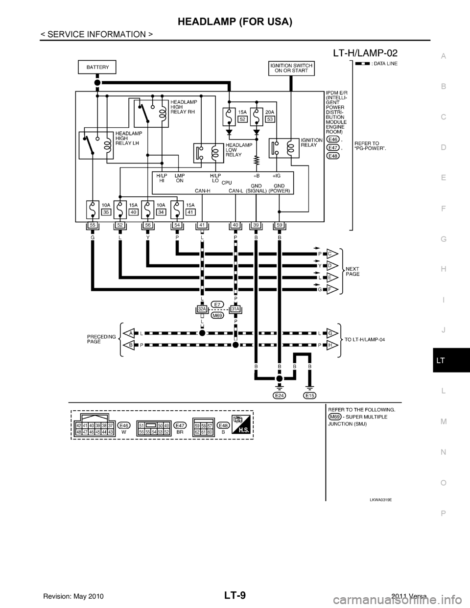
headlamps be turned ON. The CPU (centra l processing unit) located in the IPDM E/R controls ground for the
headlamp high and headlamp low relay coils. These relays direct power to the respective headlamps, which
then illuminate.
OUTLINE
Power is supplied at all times
• to headlamp high relay RH and LH (located in IPDM E/R),
• to headlamp low relay (located in IPDM E/R),
• to ignition relay (located in IPDM E/R),
• through 15A fuse (No. 52, located in IPDM E/R) and
• through 20A fuse (No. 53, located in IPDM E/R)
• to CPU located in IPDM E/R,
• through 40A fusible link (letter g , located in fuse and fusible link block)
• to BCM terminal 70,
• through 10A fuse [No. 8, located in fuse block (J/B)]
• to BCM terminal 57, and
• through 10A fuse [No. 13, located in fuse block (J/B)]
• to combination meter terminal 27.
With the ignition switch in the ON or START position, power is supplied
• to the ignition relay (located in IPDM E/R),
• through 10A fuse [No. 6, located in fuse block (J/B)]
• to BCM terminal 38,
• through 10A fuse [No. 3, located in fuse block (J/B)]
• to combination meter terminal 28.
With the ignition switch in the ACC or ON position, power is supplied
• through 10A fuse [No. 20, located in fuse block (J/B)]
• to BCM terminal 11.
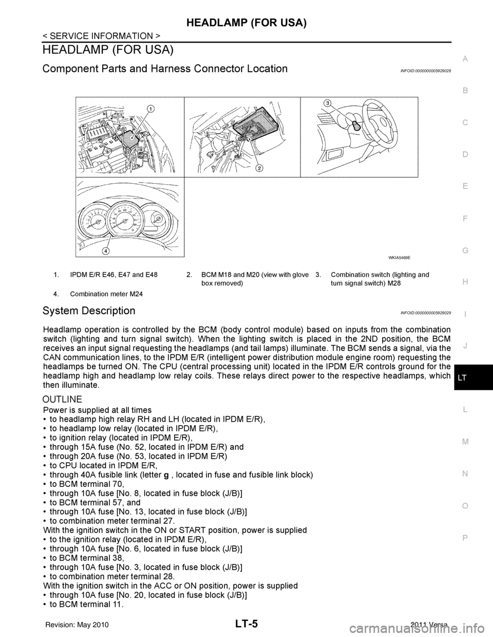
1. IPDM E/R E46, E47 and E48 2. BCM M18 and M20 (view with glove
box removed)3. Combination switch (lighting and
turn signal switch) M28
4. Combination meter M24
WKIA5469E
Revision: May 2010 2011 Versa
Page 3038 of 3787
LT-6
< SERVICE INFORMATION >
HEADLAMP (FOR USA)
Ground is supplied
• to BCM terminal 67
• to combination meter terminals 21, 22 and 23
• through grounds M57 and M61, and
• to IPDM E/R terminals 39 and 59
• through grounds E15 and E24.
HEADLAMP OPERATION
Low Beam Operation
With the lighting switch in 2ND position, the BCM receives an input signal requesting the headlamps to illumi-
nate. The BCM then sends a signal, via the CAN comm unication lines, to the IPDM E/R requesting the low
beam headlamps be turned ON. The CPU located in the IPDM E/R controls ground to the headlamp low relay
coil, which when energized, directs power
• through 15A fuse (No. 41, located in IPDM E/R)
• through IPDM E/R terminal 54
• to headlamp RH terminal 3, and
• through 15A fuse (No. 40, located in IPDM E/R)
• through IPDM E/R terminal 52
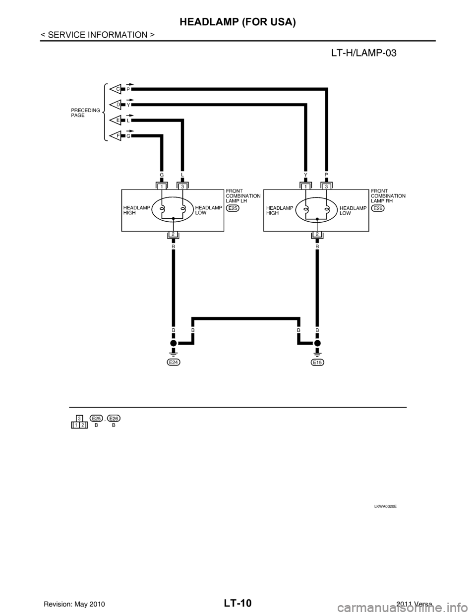
• to headlamp LH terminal 3.
Ground is supplied
• to headlamp RH and LH terminals 2
• through grounds E15 and E24.
With power and ground supplied, low beam headlamps illuminate.
High Beam Operation/Flash-to-Pass Operation
With the lighting switch in 2ND position and high beam swit ch in the HIGH position, the BCM receives an input
signal requesting the headlamp high beams to illuminate. T he flash to pass feature can be used any time and
also sends a signal to the BCM. This input signal is then communicated to the IPDM E/R and the combination
meter via the CAN communication. The CPU located in the IPDM E/R controls the headlamp high relays (LH
and RH), which when energized, directs power
• through 10A fuse (No. 34, located in IPDM E/R)
• through IPDM E/R terminal 56
• to headlamp RH terminal 1, and
• through 10A fuse (No. 35, located in IPDM E/R)
• through IPDM E/R terminal 55
• to headlamp LH terminal 1.
Ground is supplied
• to headlamp RH and LH terminal 2
• through grounds E15 and E24.
With power and ground supplied, the high beam headlamps illuminate.
The BCM sends a signal, via the CAN communication lines, to the combination meter requesting the high
beam indicator lamp be turned ON.
COMBINATION SWITCH READING FUNCTION
Refer to BCS-4, "System Description" .
EXTERIOR LAMP BATTERY SAVER CONTROL
Refer to LT-74, "System Description" .
CAN COMMUNICATION SYSTEM DESCRIPTIONINFOID:0000000005929030
Refer to LAN-7 .
Revision: May 2010 2011 Versa
Page 3039 of 3787
HEADLAMP (FOR USA)LT-7
< SERVICE INFORMATION >
C
DE
F
G H
I
J
L
M A
B
LT
N
O P
SchematicINFOID:0000000005929031
ABLWA1012GB
Revision: May 2010 2011 Versa
Page 3040 of 3787
LT-8
< SERVICE INFORMATION >
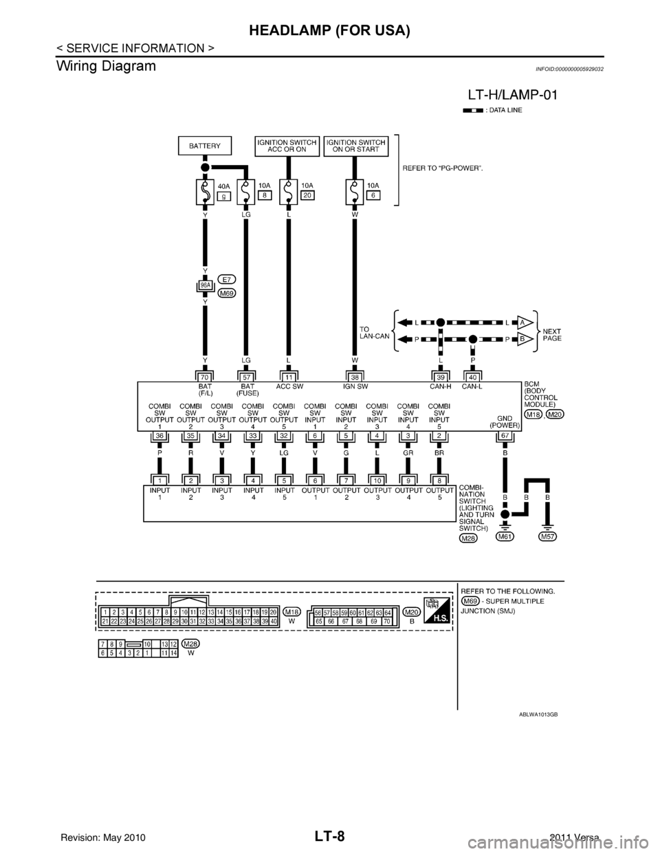
HEADLAMP (FOR USA)
Wiring Diagram
INFOID:0000000005929032
ABLWA1013GB
Revision: May 2010 2011 Versa
Page 3041 of 3787
HEADLAMP (FOR USA)LT-9
< SERVICE INFORMATION >
C
DE
F
G H
I
J
L
M A
B
LT
N
O P
LKWA0319E
Revision: May 2010 2011 Versa
Page 3042 of 3787
LT-10
< SERVICE INFORMATION >
HEADLAMP (FOR USA)
LKWA0320E
Revision: May 20102011 Versa