fuel filter NISSAN LATIO 2011 Service Workshop Manual
[x] Cancel search | Manufacturer: NISSAN, Model Year: 2011, Model line: LATIO, Model: NISSAN LATIO 2011Pages: 3787, PDF Size: 78.35 MB
Page 2539 of 3787
![NISSAN LATIO 2011 Service Workshop Manual OIL PANEM-149
< SERVICE INFORMATION > [MR18DE]
C
D
E
F
G H
I
J
K L
M A
EM
NP
O
9. Apply the sealant without breaks to the specified location using
Tool.
Use Genuine Silicone RTV Seal ant or equivalen](/img/5/57357/w960_57357-2538.png "NISSAN LATIO 2011 Service Workshop Manual OIL PANEM-149
< SERVICE INFORMATION > [MR18DE]
C
D
E
F
G H
I
J
K L
M A
EM
NP
O
9. Apply the sealant without breaks to the specified location using
Tool.
Use Genuine Silicone RTV Seal ant or equivalen")
OIL PANEM-149
< SERVICE INFORMATION > [MR18DE]
C
D
E
F
G H
I
J
K L
M A
EM
NP
O
9. Apply the sealant without breaks to the specified location using
Tool.
Use Genuine Silicone RTV Seal ant or equivalent. Refer to
GI-42, "
Recommended Chemical Product and Sealant".
10. Tighten bolts in numerical order as shown.
11. Install oil filter with the following procedure:
a. Remove foreign materials adhering to the oil filter installation surface.
b. Apply new engine oil to the oil seal contact surface of new oil fil- ter.
c. Screw oil filter manually until it touches the installation surface, then tighten it by 2/3 turn. Or tighten to specification.
12. Installation of the remaining components is in the reverse order of removal.
InspectionINFOID:0000000006413286
INSPECTION AFTER INSTALLATION
• Before starting engine, check oil/fluid levels incl uding engine coolant and engine oil. If less than required
quantity, fill to the specified level. Refer to MA-14, "
Fluids and Lubricants".
• Use procedure below to check for fuel leakage.
• Turn ignition switch ON (with engine stopped). With fuel pressure applied to fuel piping, check for fuel leak-
age at connection points.
• Start engine. With engine speed increased, check again for fuel leakage at connection points.
• Run engine to check for unusual noise and vibration. Tool number WS39930000 ( – )
1 : Oil pan (lower)
A : Liquid gasket
: Engine outside
PBIC4590E
: Engine front
PBIC3146J
Oil filter: : 17.7 N·m (1.8 kg-m, 13 ft-lb)
SMA229B
Revision: May 2010 2011 Versa
Page 2668 of 3787

FL-1
ENGINE
C
DE
F
G H
I
J
K L
M
SECTION FL
A
FL
N
O P
CONTENTS
FUEL SYSTEM
SERVICE INFORMATION .. ..........................2
PRECAUTIONS .............................................. .....2
Precaution for Supplemental Restraint System
(SRS) "AIR BAG" and "SEAT BELT PRE-TEN-
SIONER" ............................................................. ......
2
Precaution Necessary for Steering Wheel Rota-
tion After Battery Disconnect ............................... ......
2
PREPARATION ...................................................4
Special Service Tool ........................................... ......4
Commercial Service Tool ..........................................4
FUEL SYSTEM ....................................................5
Checking Fuel Line ............................................. ......5
General Precaution ...................................................5
FUEL LEVEL SENSOR UNIT, FUEL FILTER
AND FUEL PUMP ASSEMBLY .........................
6
Component .......................................................... .....6
Removal and Installation ..........................................6
FUEL TANK ......................................................10
Component .......................................................... ....10
Removal and Installation .........................................10
EVAPORATIVE EMISSION SYSTEM ...............15
Exploded View .........................................................15
Removal and Installation (HR16DE) ........................15
Exploded View .........................................................16
Removal and Installation (MR18DE) .......................16
SERVICE DATA AND SPECIFICATIONS
(SDS) .................................................................
18
Standard and Limit .............................................. ....18
Revision: May 2010 2011 Versa
Page 2673 of 3787
FL-6
< SERVICE INFORMATION >
FUEL LEVEL SENSOR UNIT, FUEL FILTER AND FUEL PUMP ASSEMBLY
FUEL LEVEL SENSOR UNIT, FUEL FILTER AND FUEL PUMP ASSEMBLY
ComponentINFOID:0000000005931057
Removal and InstallationINFOID:0000000005931058
REMOVAL
WARNING:
Be sure to read “General Precautions” be fore working on the fuel system. Refer to FL-5, "
General Pre-
caution".
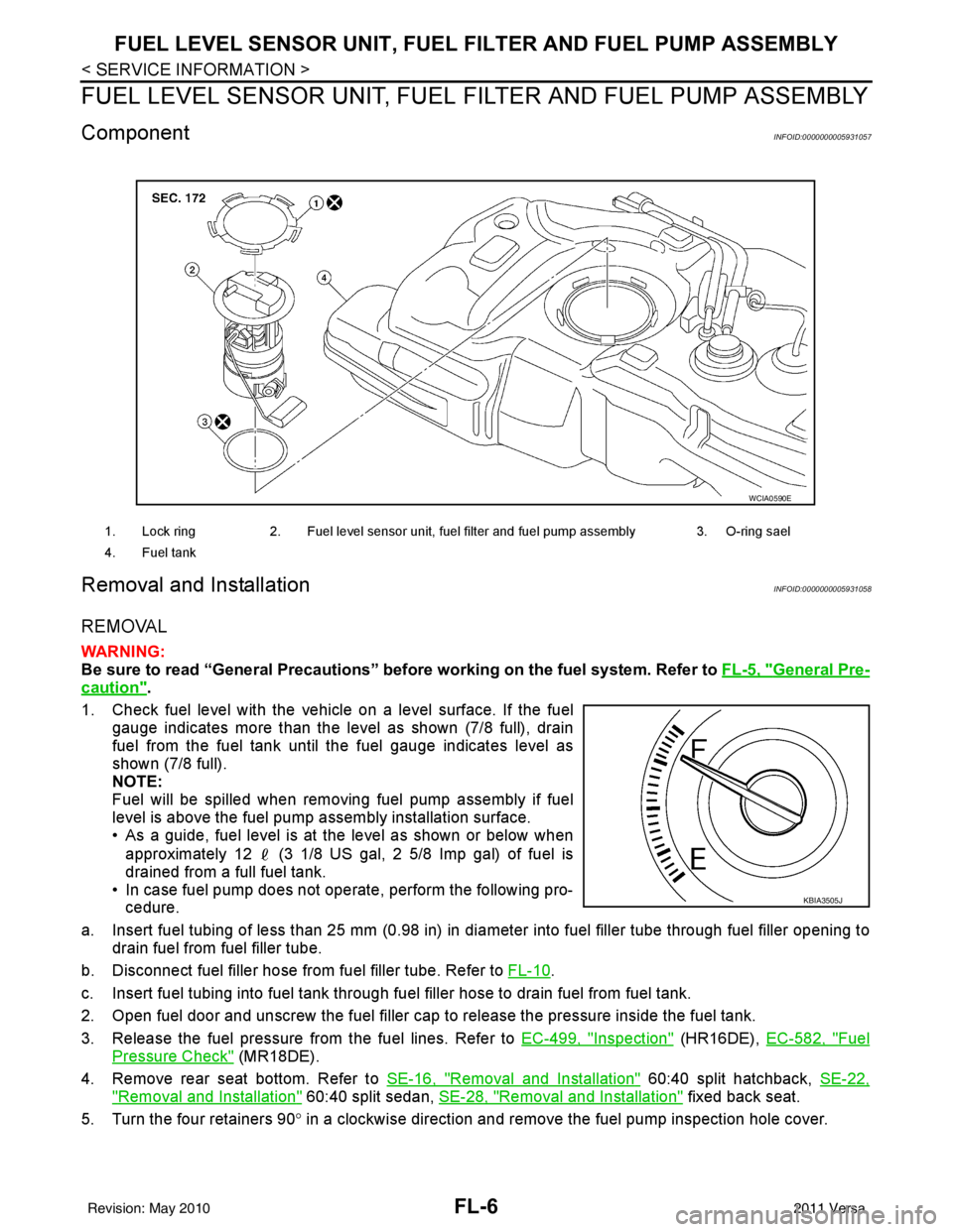
1. Check fuel level with the vehicle on a level surface. If the fuel gauge indicates more than the level as shown (7/8 full), drain
fuel from the fuel tank until the fuel gauge indicates level as
shown (7/8 full).
NOTE:
Fuel will be spilled when removing fuel pump assembly if fuel
level is above the fuel pump assembly installation surface.
• As a guide, fuel level is at the level as shown or below when
approximately 12 (3 1/8 US gal, 2 5/8 Imp gal) of fuel is
drained from a full fuel tank.
• In case fuel pump does not operate, perform the following pro- cedure.
a. Insert fuel tubing of less than 25 mm (0.98 in) in di ameter into fuel filler tube through fuel filler opening to
drain fuel from fuel filler tube.
b. Disconnect fuel filler hose from fuel filler tube. Refer to FL-10
.
c. Insert fuel tubing into fuel tank through f uel filler hose to drain fuel from fuel tank.
2. Open fuel door and unscrew the fuel filler cap to release the pressure inside the fuel tank.
3. Release the fuel pressure from the fuel lines. Refer to EC-499, "
Inspection" (HR16DE), EC-582, "Fuel
Pressure Check" (MR18DE).
4. Remove rear seat bottom. Refer to SE-16, "
Removal and Installation" 60:40 split hatchback, SE-22,
"Removal and Installation" 60:40 split sedan, SE-28, "Removal and Installation" fixed back seat.
5. Turn the four retainers 90 ° in a clockwise direction and remove the fuel pump inspection hole cover.
1. Lock ring 2. Fuel level sensor unit, fuel filter and fuel pump assembly 3. O-ring sael
4. Fuel tank
WCIA0590E
KBIA3505J
Revision: May 2010 2011 Versa
Page 2674 of 3787
FUEL LEVEL SENSOR UNIT, FUEL FILTER AND FUEL PUMP ASSEMBLYFL-7
< SERVICE INFORMATION >
C
DE
F
G H
I
J
K L
M A
FL
NP
O
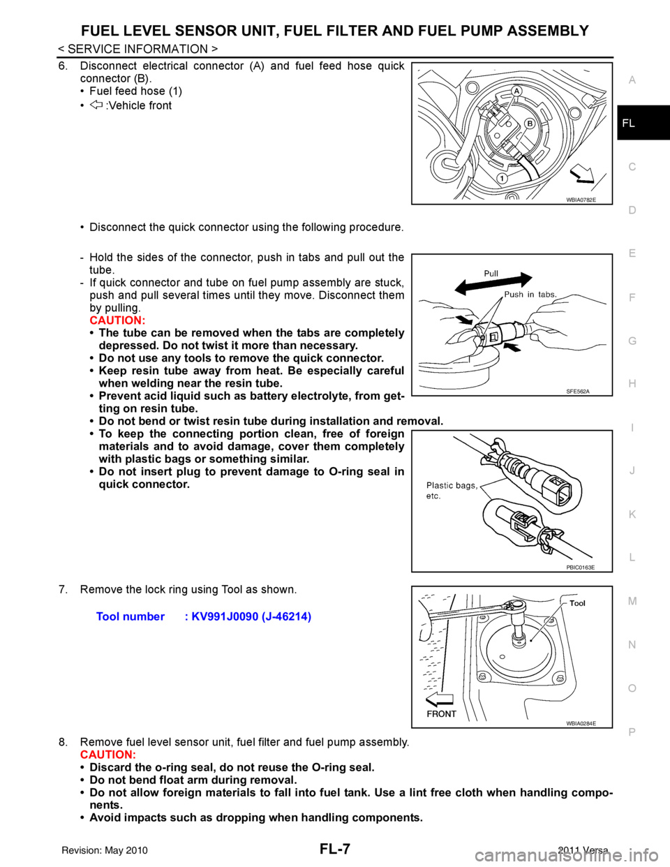
6. Disconnect electrical connector (A) and fuel feed hose quick
connector (B).
• Fuel feed hose (1)
• :Vehicle front
• Disconnect the quick connector using the following procedure.
- Hold the sides of the connector, push in tabs and pull out thetube.
- If quick connector and tube on fuel pump assembly are stuck, push and pull several times until they move. Disconnect them
by pulling.
CAUTION:
• The tube can be removed when the tabs are completely
depressed. Do not twist it more than necessary.
• Do not use any tools to remove the quick connector.
• Keep resin tube away from heat. Be especially careful
when welding near the resin tube.
• Prevent acid liquid such as battery electrolyte, from get- ting on resin tube.
• Do not bend or twist resin tube during installation and removal.
• To keep the connecting port ion clean, free of foreign
materials and to avoid damage, cover them completely
with plastic bags or something similar.
• Do not insert plug to prevent damage to O-ring seal in quick connector.
7. Remove the lock ring using Tool as shown.
8. Remove fuel level sensor unit, fuel filter and fuel pump assembly. CAUTION:
• Discard the o-ring seal, do not reuse the O-ring seal.
• Do not bend float arm during removal.
• Do not allow foreign materials to fall into fuel tank. Use a lint free cloth when handling compo-
nents.
• Avoid impacts such as droppin g when handling components.
WBIA0782E
SFE562A
PBIC0163E
Tool number : KV991J0090 (J-46214)
WBIA0284E
Revision: May 2010 2011 Versa
Page 2675 of 3787
FL-8
< SERVICE INFORMATION >
FUEL LEVEL SENSOR UNIT, FUEL FILTER AND FUEL PUMP ASSEMBLY
INSPECTION AFTER REMOVAL
Make sure that the fuel level sensor unit, fuel filter and fuel pump is free from defects and foreign materials.
INSTALLATION
Installation is in the reverse order of removal.
Fuel Level Sensor Unit, Fuel Filter and Fuel Pump Assembly
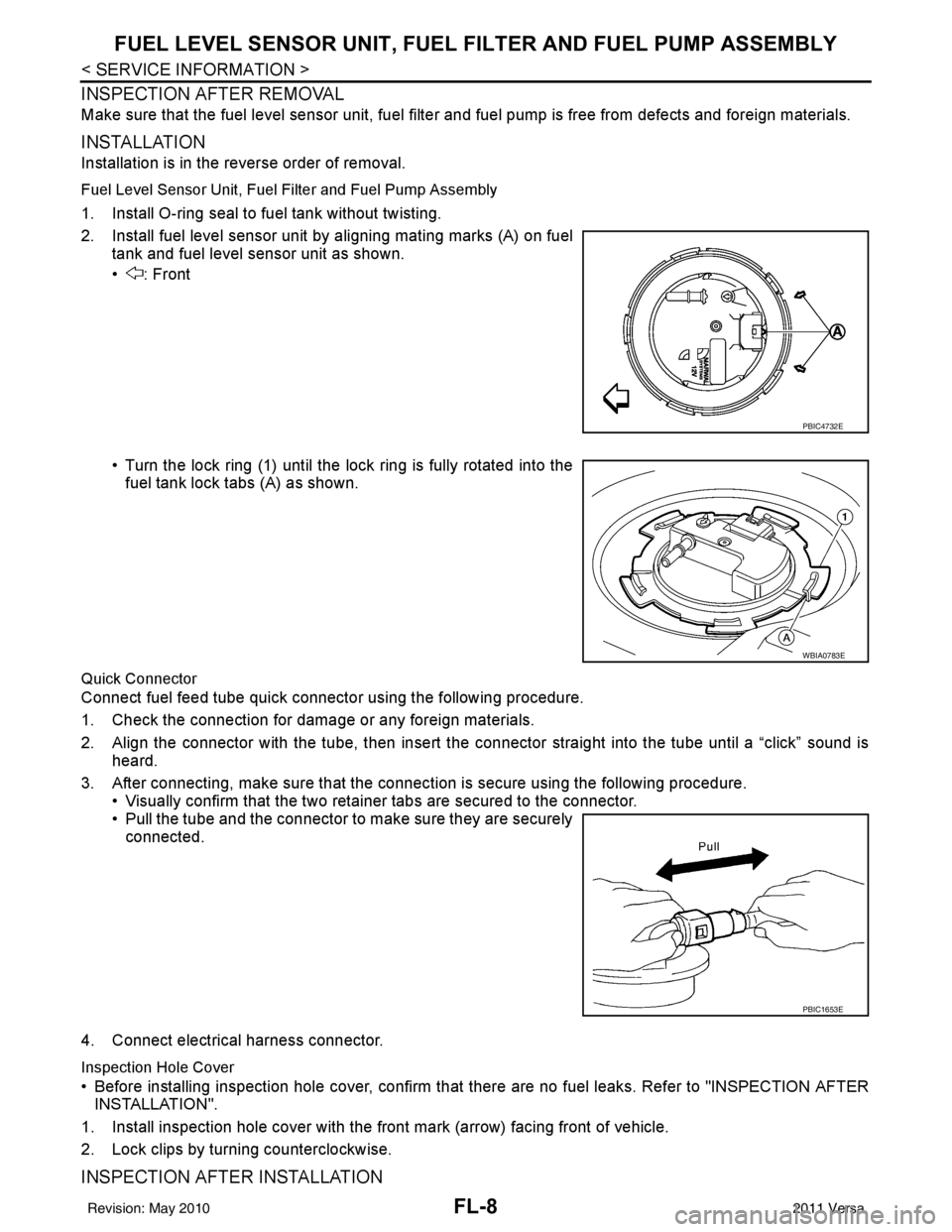
1. Install O-ring seal to fuel tank without twisting.
2. Install fuel level sensor unit by aligning mating marks (A) on fuel
tank and fuel level sensor unit as shown.
• : Front
• Turn the lock ring (1) until the lock ring is fully rotated into thefuel tank lock tabs (A) as shown.
Quick Connector
Connect fuel feed tube quick connector using the following procedure.
1. Check the connection for damage or any foreign materials.
2. Align the connector with the tube, then insert the connector straight into the tube until a “click” sound is heard.
3. After connecting, make sure that the connec tion is secure using the following procedure.
• Visually confirm that the two retainer tabs are secured to the connector.
• Pull the tube and the connector to make sure they are securely connected.
4. Connect electrical harness connector.
Inspection Hole Cover
• Before installing inspection hole cover, confirm that there are no fuel leaks. Refer to "INSPECTION AFTER
INSTALLATION".
1. Install inspection hole cover with the front mark (arrow) facing front of vehicle.
2. Lock clips by turning counterclockwise.
INSPECTION AFTER INSTALLATION
PBIC4732E
WBIA0783E
PBIC1653E
Revision: May 2010 2011 Versa
Page 2676 of 3787

FUEL LEVEL SENSOR UNIT, FUEL FILTER AND FUEL PUMP ASSEMBLYFL-9
< SERVICE INFORMATION >
C
DE
F
G H
I
J
K L
M A
FL
NP
O
Use the following procedure to check for fuel leaks.
1. Turn ignition switch “ON” (without starting the engi
ne), to check the connections for fuel leaks with the
electric fuel pump applying pressure to the fuel piping.
2. Start the engine and let it idle to check that ther e are no fuel leaks at the fuel system connections.
Revision: May 2010 2011 Versa
Page 3172 of 3787
MA-1
MAINTENANCE
C
DE
F
G H
I
J
K
M
SECTION MA
A
B
MA
N
O P
CONTENTS
MAINTENANCE
SERVICE INFORMATION .. ..........................3
PRECAUTIONS .............................................. .....3
Precaution for Supplemental Restraint System
(SRS) "AIR BAG" and "SEAT BELT PRE-TEN-
SIONER" ............................................................. ......
3
Precaution Necessary for Steering Wheel Rota-
tion After Battery Disconnect ............................... ......
3
PREPARATION ...................................................5
Special Service Tool ........................................... ......5
Commercial Service Tool ..........................................6
GENERAL MAINTENANCE ........................... .....7
Explanation of General Maintenance .................. ......7
General Maintenance ................................................7
PERIODIC MAINTENANCE ................................9
Introduction of Periodic Maintenance .................. ......9
Schedule 1 ................................................................9
Schedule 2 ..............................................................11
RECOMMENDED FLUIDS AND LUBRI-
CANTS ................................................................
14
Fluids and Lubricants .......................................... ....14
SAE Viscosity Number ............................................15
Anti-freeze Coolant Mixture Ratio ...........................15
ENGINE MAINTENANCE (HR16DE) .................16
DRIVE BELT .......................................................... ....16
DRIVE BELT : Checking .........................................16
DRIVE BELT : Tension Adjustment ........................16
ENGINE COOLANT ............................................... ....17
ENGINE COOLANT : Inspection .............................17
ENGINE COOLANT : Changing Engine Coolant ....17
FUEL LINES .......................................................... ....19
FUEL LINES : Checking Fuel Line ..........................19
AIR CLEANER FILTER ......................................... ....19
AIR CLEANER FILTER : Removal and Installation
....
20
ENGINE OIL ........................................................... ....20
ENGINE OIL : Inspection .........................................20
ENGINE OIL : Draining ............................................22
ENGINE OIL : Refilling ............................................22
OIL FILTER ............................................................ ....23
OIL FILTER : Removal and Installation ...................23
SPARK PLUG (HR16DE) ...................................... ....23
SPARK PLUG (HR16DE) : Exploded View .............24
SPARK PLUG (HR16DE) : Removal and Installa-
tion ....................................................................... ....
24
EVAP VAPOR LINES ............................................ ....25
EVAP VAPOR LINES : Checking EVAP Vapor
Line ..........................................................................
25
ENGINE MAINTENANCE (MR18DE) ...............26
DRIVE BELT .......................................................... ....26
DRIVE BELT : Component ......................................26
DRIVE BELT : Checking Drive Belts .......................26
DRIVE BELT : Tension Adjustment .........................26
ENGINE COOLANT ............................................... ....26
ENGINE COOLANT : Inspection .............................26
ENGINE COOLANT : Changing Engine Coolant ....27
FUEL LINES ........................................................... ....29
FUEL LINES : Checking Fuel Line ..........................29
AIR CLEANER FILTER ......................................... ....29
AIR CLEANER FILTER : Component ......................29
AIR CLEANER FILTER : Changing Air Cleaner
Filter .........................................................................
30
ENGINE OIL ........................................................... ....30
ENGINE OIL : Inspection .........................................30
ENGINE OIL : Changing Engine Oil ........................32
OIL FILTER ............................................................ ....33
Revision: May 2010 2011 Versa
Page 3180 of 3787
PERIODIC MAINTENANCEMA-9
< SERVICE INFORMATION >
C
DE
F
G H
I
J
K
M A
B
MA
N
O P
PERIODIC MAINTENANCE
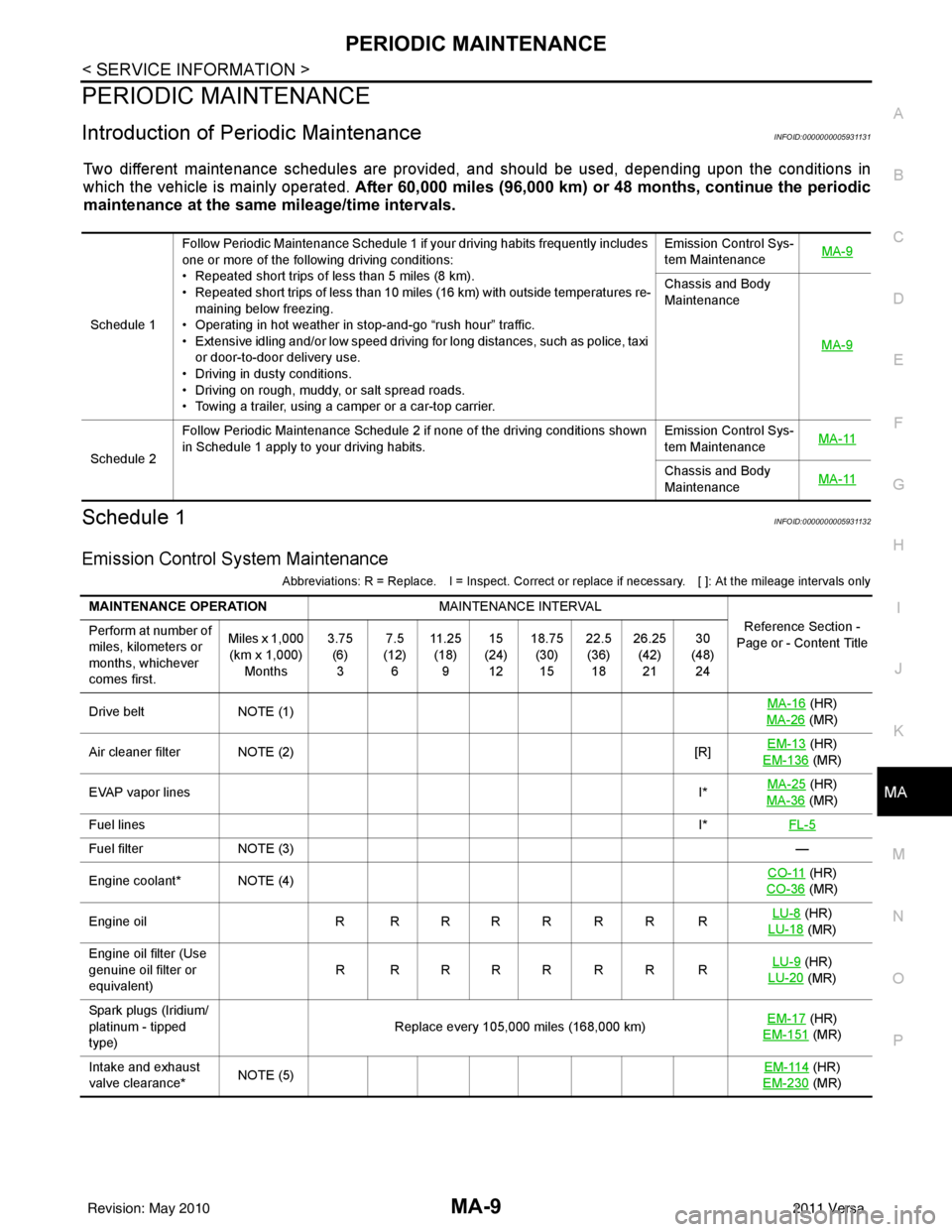
Introduction of Periodic MaintenanceINFOID:0000000005931131
Two different maintenance schedules are provi ded, and should be used, depending upon the conditions in
which the vehicle is mainly operated. After 60,000 miles (96,000 km) or 48 months, continue the periodic
maintenance at the same mileage/time intervals.
Schedule 1INFOID:0000000005931132
Emission Control System Maintenance
Abbreviations: R = Replace. I = Inspect. Correct or r eplace if necessary. [ ]: At the mileage intervals only
Schedule 1Follow Periodic Maintenance Schedule 1 if your driving habits frequently includes
one or more of the following driving conditions:
• Repeated short trips of less than 5 miles (8 km).
• Repeated short trips of less than 10 miles (16 km) with outside temperatures re-
maining below freezing.
• Operating in hot weather in stop-and-go “rush hour” traffic.
• Extensive idling and/or low speed driving for long distances, such as police, taxi
or door-to-door delivery use.
• Driving in dusty conditions.
• Driving on rough, muddy, or salt spread roads.
• Towing a trailer, using a camper or a car-top carrier. Emission Control Sys-
tem Maintenance
MA-9
Chassis and Body
Maintenance
MA-9
Schedule 2Follow Periodic Maintenance Schedule 2 if none of the driving conditions shown
in Schedule 1 apply to your driving habits.
Emission Control Sys-
tem Maintenance
MA-11Chassis and Body
Maintenance
MA-11
MAINTENANCE OPERATION
MAINTENANCE INTERVAL
Reference Section -
Page or - Content Title
Perform at number of
miles, kilometers or
months, whichever
comes first. Miles x 1,000
(km x 1,000) Months 3.75
(6)3 7.5
(12) 6 11 . 2 5
(18) 9 15
(24) 12 18.75
(30)15 22.5
(36) 18 26.25
(42)21 30
(48) 24
Drive belt NOTE (1) MA-16
(HR)
MA-26
(MR)
Air cleaner filter NOTE (2) [R]EM-13
(HR)
EM-136
(MR)
EVAP vapor lines I*MA-25
(HR)
MA-36
(MR)
Fuel lines I*FL-5
Fuel filter NOTE (3) —
Engine coolant* NOTE (4) CO-11
(HR)
CO-36
(MR)
Engine oil R R R R R R R R LU-8
(HR)
LU-18
(MR)
Engine oil filter (Use
genuine oil filter or
equivalent) RRRRRRRR
LU-9
(HR)
LU-20
(MR)
Spark plugs (Iridium/
platinum - tipped
type) Replace every 105,000 miles (168,000 km)
EM-17
(HR)
EM-151
(MR)
Intake and exhaust
valve clearance* NOTE (5) EM-114
(HR)
EM-230
(MR)
Revision: May 2010 2011 Versa
Page 3181 of 3787
![NISSAN LATIO 2011 Service Workshop Manual MA-10
< SERVICE INFORMATION >
PERIODIC MAINTENANCE
Abbreviations: R = Replace. I = Inspect. Correct or replace if necessary. [ ]: At the mileage intervals only
(1) After 60,000 miles (96,000 km) or 48](/img/5/57357/w960_57357-3180.png "NISSAN LATIO 2011 Service Workshop Manual MA-10
< SERVICE INFORMATION >
PERIODIC MAINTENANCE
Abbreviations: R = Replace. I = Inspect. Correct or replace if necessary. [ ]: At the mileage intervals only
(1) After 60,000 miles (96,000 km) or 48")
MA-10
< SERVICE INFORMATION >
PERIODIC MAINTENANCE
Abbreviations: R = Replace. I = Inspect. Correct or replace if necessary. [ ]: At the mileage intervals only
(1) After 60,000 miles (96,000 km) or 48 months, inspect every 15,000 miles (24,000 km) or 12 months. Replace the drive belts i f found
damaged.
(2) If operating mainly in dusty conditions, more frequent maintenance may be required.
(3) Maintenance-free item. For service procedures, refer to the FL section.
(4) First replacement interval is 105,000 miles (168,000 km) or 84 months. After first replacement, replace every 75,000 miles (120,000
km) or 60 months. Use only Genuine NISSAN long life Antifreeze/Coolant (blue) or equivalent with proper mixture ratio of 50% an ti-
freeze and 50% demineralized or distilled water. Mixing any other type of coolant or the use of non-distilled water will reduce the life
expectancy of the factory fill coolant.
(5) Periodic maintenance is not required. However, if valve noise increases, inspect valve clearance.
* Maintenance items and intervals with “*” are recommended by NISSAN for reliable vehicle operation. The owner need not perform
such maintenance in order to maintain the emission warranty or manufacturer recall liability. Other maintenance items and inter vals are
required.
Chassis and Body Maintenance
Abbreviations: R = Replace. I = Inspec t. Correct or replace if necessary.
MAINTENANCE OPERATION MAINTENANCE INTERVAL
Reference Section -
Page or - Content Title
Perform at number of
miles, kilometers or
months, whichever
comes first. Miles x
1,000
(km x
1,000)
Months 33.75
(54)27 37.5
(60) 30 41.25
(66)33 45
(72) 36 48.75
(78)39 52.5
(84) 42 56.25
(90)45 60
(96) 48
Drive belt NOTE
(1) I*EM-13
(HR)
EM-132
(MR)
Air cleaner filter NOTE
(2) [R]
EM-16
(HR)
EM-135
(MR)
EVAP vapor lines I*MA-25
(HR)
MA-36
(MR)
Fuel lines I*MA-19
, MA-29
Fuel filter NOTE
(3) —
Engine coolant* NOTE
(4) CO-11
(HR)
CO-36
(MR)
Engine oil R R R R R R R R LU-8
(HR)
LU-18
(MR)
Engine oil filter (Use
genuine oil filter or
equivalent) R R R R RRRR
LU-9
(HR)
LU-20
(MR)
Spark plugs (Iridium/
platinum - tipped type) Replace every 105,000 miles (168,000 km) EM-17
(HR)
EM-151
(MR)
Intake and exhaust
valve clearance* NOTE
(5) EM-114
(HR)
EM-230
(MR)
MAINTENANCE OPERATION MAINTENANCE INTERVAL
Reference Section -
Page or -
Content Title
Perform at number of
miles, kilometers or
months, whichever
comes first. Miles x
1,000
(km x
1,000)
Months 3.75
(6)3 7.5
(12) 6 11 . 2 5
(18) 9 15
(24) 12 18.75
(30)15 22.5
(36) 18 26.25
(42)21 30
(48) 24
Brake lines & cables IIMA-46
Brake pads, rotors,
drums & linings IIII MA-46
MA-46
Revision: May 2010
2011 Versa
Page 3183 of 3787
![NISSAN LATIO 2011 Service Workshop Manual MA-12
< SERVICE INFORMATION >
PERIODIC MAINTENANCE
Abbreviations: R = Replace. I = Inspect. Correct or replace if necessary. [ ]: At the mileage intervals only
(1) After 60,000 miles (96,000 km) or 48](/img/5/57357/w960_57357-3182.png "NISSAN LATIO 2011 Service Workshop Manual MA-12
< SERVICE INFORMATION >
PERIODIC MAINTENANCE
Abbreviations: R = Replace. I = Inspect. Correct or replace if necessary. [ ]: At the mileage intervals only
(1) After 60,000 miles (96,000 km) or 48")
MA-12
< SERVICE INFORMATION >
PERIODIC MAINTENANCE
Abbreviations: R = Replace. I = Inspect. Correct or replace if necessary. [ ]: At the mileage intervals only
(1) After 60,000 miles (96,000 km) or 48 months, inspect every 15,000 miles (24,000 km) or 12 months. Replace the drive belt if found
damaged or if the auto belt tensioner reading reaches the maximum limit.
(2) Maintenance-free item. For service procedures, refer to the FL section.
(3) First replacement interval is 105,000 miles (168,000 km) or 84 months. After first replacement, replace every 75,000 miles (120,000
km) or 60 months. Use only Genuine NISSAN long life Antifreeze/Coolant (blue) or equivalent with proper mixture ratio of 50% an ti-
freeze and 50% demineralized or distilled water. Mixing any other type of coolant or the use of non-distilled water will reduce the life
expectancy of the factory fill coolant.
(4) Periodic maintenance is not required. However, if valve noise increases, inspect valve clearance.
Maintenance items and intervals with “*” are recommended by NISSAN for reliab le vehicle operation. The owner need not perform such
maintenance in order to maintain the emission warranty or manufacturer recall liability. Other maintenance items and intervals are
required.
Chassis and Body Maintenance
Abbreviations: R = Replace. I = Inspec t. Correct or replace if necessary. .
MAINTENANCE OPERATION MAINTENANCE INTERVAL
Reference
Section - Page
or - Content Ti- tle
Perform at number of miles,
kilometers or months, which-
ever comes first. Miles x
1,000
(km x
1,000)
Months 7.5
(12) 6 15
(24) 12 22.5
(36) 18 30
(48) 24 37.5
(60) 30 45
(72) 36 52.5
(84) 42 60
(96) 48
Drive belt NOTE (1) I*EM-13
(HR)
EM-132
(MR)
Air cleaner filter [R][R]EM-16
(HR)
EM-136
(MR)
EVAP vapor lines I*I*MA-25
(HR)
MA-36
(MR)
Fuel lines I*I*FL-5
Fuel filter NOTE (2) —
Engine coolant* NOTE (3) CO-11
(HR)
CO-36
(MR)
Engine oil RR R RRRRR LU-8
(HR)
LU-18
(MR)
Engine oil filter (Use genuine
oil filter or equivalent.) RR R RRRRR LU-9
(HR)
LU-20
(MR)
Spark plugs (Iridium/plati-
num - tipped type) Replace every 105,000 miles (168,000 km) EM-17
(HR)
EM-151
(MR)
Intake and exhaust valve
clearance* NOTE (4)
EM-114
(HR)
EM-230
(MR)
MAINTENANCE OPERATION MAINTENANCE INTERVAL
Reference Sec-
tion - Page or -
Content Title
Perform at number of miles, kilo-
meters or months, whichever
comes first. Miles x 1,000
(km x 1,000)
Months 7.5
(12)
6 15
(24)
12 22.5
(36)
18 30
(48)
24 37.5
(60)
30 45
(72)
36 52.5
(84)
42 60
(96)
48
B ra ke lin e s & cab le s IIII MA-46
Brake pads, rotors, drums & lin-
ings IIII
MA-46
MA-46
Manual transaxle oil or automatic
transaxle fluid IIIIMT-11
(RS5F91R)
MT-54
(RS6F94R)
AT- 1 7
(A/T)
C VT flu id NO TE (1) IIII CVT-15
(RE0F08B)
Steering gear & linkage, axle &
suspension parts II
PS-15
, MA-47
Tire rotation NOTE (2) WT-7
Revision: May 2010 2011 Versa