NISSAN LEAF 2015 1.G Dismantling Guide
Manufacturer: NISSAN, Model Year: 2015, Model line: LEAF, Model: NISSAN LEAF 2015 1.GPages: 45, PDF Size: 1.63 MB
Page 1 of 45
2015 LEAF
Dismantling Guide
Page 2 of 45
Foreword
This
manual describes dismantling operations and related warnings for this vehicle.
This vehicle is an electrically driven car equipped with a high voltage battery pack. Failure to follow
recommended practices during dismantling will cause death or serious personal injury.
Please read this manual in advance in order to understand the features of this vehicle and to help you deal
with dismantling operations involving this vehicle. Follow the procedures in order to help assure a safe
and successful dismantling operation.
This manual is periodically updated. If you are not viewing this manual on the Nissan web site, we urge you
to go to www.nissanusa.com orwww.nissan-techinfo.com to make sure you have the most recent version of
this
manual.
NISSAN EMERGENCY CONTACT INFORMATION • Nissan EV Customer Support: 1-877-664-2738 (Hours of operation are Monday-Friday 7am -7pm, Saturday 8am - 4:30pm Central time zone)
• Nissan Consumer Affairs: 1-800-647-7261 (US) or 1-800-387-0122 (Canada) (Hours of operation are 8am - 5pm (Monday-Friday) Eastern, Central and Pacific time zones)
IMPORTANT INFORMATION ABOUT THIS MANUAL
You may see various symbols in this manual. They have the following meanings: This symbol is used to inform you of an operation which will result in death or serious personal injury if
instructions
are not followed.
Example: Touching high voltage components without using the appropriate protective equipment will result
in electrocution. This symbol is used to inform you of an operation which may cause death or serious personal injury if
instructions
are not followed.This symbol is used to inform you of an operation which may cause personal injury or component damage if
instructions
are not followed.
Please note that there may be differences between this manual and the vehicle specification due to
specification changes.
DG–2
Page 3 of 45
Table of Contents
FOREWORD
. . . . . . . . . . . . . . . . . . . . . . . . . . . . . . . . . . . . . . . . . . . . . . . . . . . . . . . . . . . . . . . . . . . . DG–2
NISSAN EMERGENCY CONTACT INFORMATION . . . . . . . . . . . . . . . . . . . . . . . . . . . . . . . . . . . DG–2
IMPORTANT INFORMATION ABOUT THIS MANUAL . . . . . . . . . . . . . . . . . . . . . . . . . . . . . . . . . . DG–2
1. ABOUT THE NISSAN LEAF® . . . . . . . . . . . . . . . . . . . . . . . . . . . . . . . . . . . . . . . . . . . . . . . . . . . . DG–5 1-1 LEAF IDENTIFICATION . . . . . . . . . . . . . . . . . . . . . . . . . . . . . . . . . . . . . . . . . . . . . . . . . . . . . DG–6 1-1.1 EXTERIOR . . . . . . . . . . . . . . . . . . . . . . . . . . . . . . . . . . . . . . . . . . . . . . . . . . . . . . . . . . DG–6
1-1.2 INTERIOR COMPONENT LOCATION . . . . . . . . . . . . . . . . . . . . . . . . . . . . . . . . . . . . . DG–7
1-2 VEHICLE IDENTIFICATION NUMBER (VIN) LAYOUT . . . . . . . . . . . . . . . . . . . . . . . . . . . . . . DG–8
1-3 WARNING AND INDICATOR LAMP INFORMATION . . . . . . . . . . . . . . . . . . . . . . . . . . . . . . DG–8
2. BASIC HIGH VOLTAGE INFORMATION . . . . . . . . . . . . . . . . . . . . . . . . . . . . . . . . . . . . . . . . . . . DG–9
2-1 HIGH VOLTAGE-RELATED AND 12V-RELATED COMPONENT LOCATIONS AND
DESCRIPTIONS . . . . . . . . . . . . . . . . . . . . . . . . . . . . . . . . . . . . . . . . . . . . . . . . . . . . . . . . . . . . . . DG–9 2-1.1 LI-ION BATTERY PACK SPECIFICATIONS . . . . . . . . . . . . . . . . . . . . . . . . . . . . . . . . DG–11
2-2 HIGH VOLTAGE SAFETY MEASURES . . . . . . . . . . . . . . . . . . . . . . . . . . . . . . . . . . . . . . . . DG–11 2-2.1 WARNING LABEL . . . . . . . . . . . . . . . . . . . . . . . . . . . . . . . . . . . . . . . . . . . . . . . . . . . DG–11
2-3 HIGH VOLTAGE CIRCUIT SHUT-OFF SYSTEM . . . . . . . . . . . . . . . . . . . . . . . . . . . . . . . . . DG–12
2-4 PREVENTING ELECTRICAL SHOCK . . . . . . . . . . . . . . . . . . . . . . . . . . . . . . . . . . . . . . . . . DG–12
3. PREPARATION FOR DISMANTLING . . . . . . . . . . . . . . . . . . . . . . . . . . . . . . . . . . . . . . . . . . . . . . DG–13
3-1 DISCHARGING PROCEDURES . . . . . . . . . . . . . . . . . . . . . . . . . . . . . . . . . . . . . . . . . . . . . DG–13
3-2 PREPARATION ITEMS . . . . . . . . . . . . . . . . . . . . . . . . . . . . . . . . . . . . . . . . . . . . . . . . . . . . DG–15
3-3 PERSONAL PROTECTIVE EQUIPMENT (PPE) AND INSULATED TOOLS . . . . . . . . . . . . . DG–163-3.1 PERSONAL PROTECTIVE EQUIPMENT (PPE) PROTECTIVE WEAR CONTROL . . DG–16
3-3.2 DAILY INSPECTION . . . . . . . . . . . . . . . . . . . . . . . . . . . . . . . . . . . . . . . . . . . . . . . . . DG–16
3-3.3 INSULATED TOOLS . . . . . . . . . . . . . . . . . . . . . . . . . . . . . . . . . . . . . . . . . . . . . . . . . DG–16
3-4 HIGH VOLTAGE SYSTEM SHUT-DOWN PROCEDURES . . . . . . . . . . . . . . . . . . . . . . . . . DG–16 3-4.1 REMOVING THE CHARGE CONNECTOR . . . . . . . . . . . . . . . . . . . . . . . . . . . . . . . . DG–18
3-4.2 INDICATIONS THE HIGH VOLTAGE SYSTEM IS ON . . . . . . . . . . . . . . . . . . . . . . . . DG–20
3-4.3 POWERING DOWN THE HIGH VOLTAGE SYSTEM . . . . . . . . . . . . . . . . . . . . . . . . DG–20
3-4.4 PRIMARY PROCEDURE . . . . . . . . . . . . . . . . . . . . . . . . . . . . . . . . . . . . . . . . . . . . . . DG–20
3-4.5 ALTERNATE PROCEDURE 1 (REMOVE FUSES) . . . . . . . . . . . . . . . . . . . . . . . . . . . DG–21
3-4.6 ALTERNATE PROCEDURE 2 (REMOVE SERVICE PLUG) . . . . . . . . . . . . . . . . . . . . DG–24
3-5 CUTTING THE VEHICLE BODY . . . . . . . . . . . . . . . . . . . . . . . . . . . . . . . . . . . . . . . . . . . . . DG–26 3-5.1 SRS AIR BAG SYSTEM COMPONENTS LOCATION . . . . . . . . . . . . . . . . . . . . . . . . DG–27
3-5.2 VEHICLE CUT SHEET . . . . . . . . . . . . . . . . . . . . . . . . . . . . . . . . . . . . . . . . . . . . . . . . DG–28
3-5.3 WATER SUBMERSION . . . . . . . . . . . . . . . . . . . . . . . . . . . . . . . . . . . . . . . . . . . . . . . DG–29
DG–3
Page 4 of 45
3-5.4 VEHICLE FIRE . . . . . . . . . . . . . . . . . . . . . . . . . . . . . . . . . . . . . . . . . . . . . . . . .
. . . . . DG–29
3-6 LI-ION BATTERY DAMAGE AND FLUID LEAKS . . . . . . . . . . . . . . . . . . . . . . . . . . . . . . . . . DG–30
4. JUMP STARTING . . . . . . . . . . . . . . . . . . . . . . . . . . . . . . . . . . . . . . . . . . . . . . . . . . . . . . . . . . . . . DG–31
4-1 JUMP STARTING PROCEDURES . . . . . . . . . . . . . . . . . . . . . . . . . . . . . . . . . . . . . . . . . . . . DG–32
4-2 P (PARK) POSITION RELEASE PROCEDURE . . . . . . . . . . . . . . . . . . . . . . . . . . . . . . . . . . DG–334-2.1 RESET PROCEDURE . . . . . . . . . . . . . . . . . . . . . . . . . . . . . . . . . . . . . . . . . . . . . . . . DG–35
4-3 STORING THE VEHICLE . . . . . . . . . . . . . . . . . . . . . . . . . . . . . . . . . . . . . . . . . . . . . . . . . . DG–35
5. DISMANTLING INFORMATION . . . . . . . . . . . . . . . . . . . . . . . . . . . . . . . . . . . . . . . . . . . . . . . . . . DG–37 5-1 PRECAUTIONS FOR HANDLING HIGH VOLTAGE LITHIUM ION (LI-ION) BATTERY . . . . DG–37
5-2 LITHIUM-ION (LI-ION) BATTERY PACK REMOVAL . . . . . . . . . . . . . . . . . . . . . . . . . . . . . . DG–395-2.1 EXPLODED VIEW . . . . . . . . . . . . . . . . . . . . . . . . . . . . . . . . . . . . . . . . . . . . . . . . . . . DG–39
5-2.2 REMOVAL PROCEDURE . . . . . . . . . . . . . . . . . . . . . . . . . . . . . . . . . . . . . . . . . . . . . DG–40
5-3 RECOVERY/RECYCLING OF THE LI-ION HIGH VOLTAGE BATTERY . . . . . . . . . . . . . . . DG–44
DG–4
Page 5 of 45
1. About The Nissan LEAF®
This
vehicle uses two types of batteries. One is a 12V battery that is the same as the battery in vehicles
powered by internal combustion engines, and the other is the Lithium-ion (Li-ion) battery (high voltage) for
the traction motor which propels the vehicle. The Li-ion battery is encased in steel and mounted underneath
the vehicle.
The vehicle must be plugged-in in order for the Li-ion battery to be recharged. Additionally, the vehicle
system can recharge the Li-ion battery by converting driving force into electricity while the vehicle is
decelerating or being driven downhill. This is called regenerative charging. This vehicle is considered to be
an environmentally friendly vehicle because it does not emit exhaust gases.
DG–5
Page 6 of 45
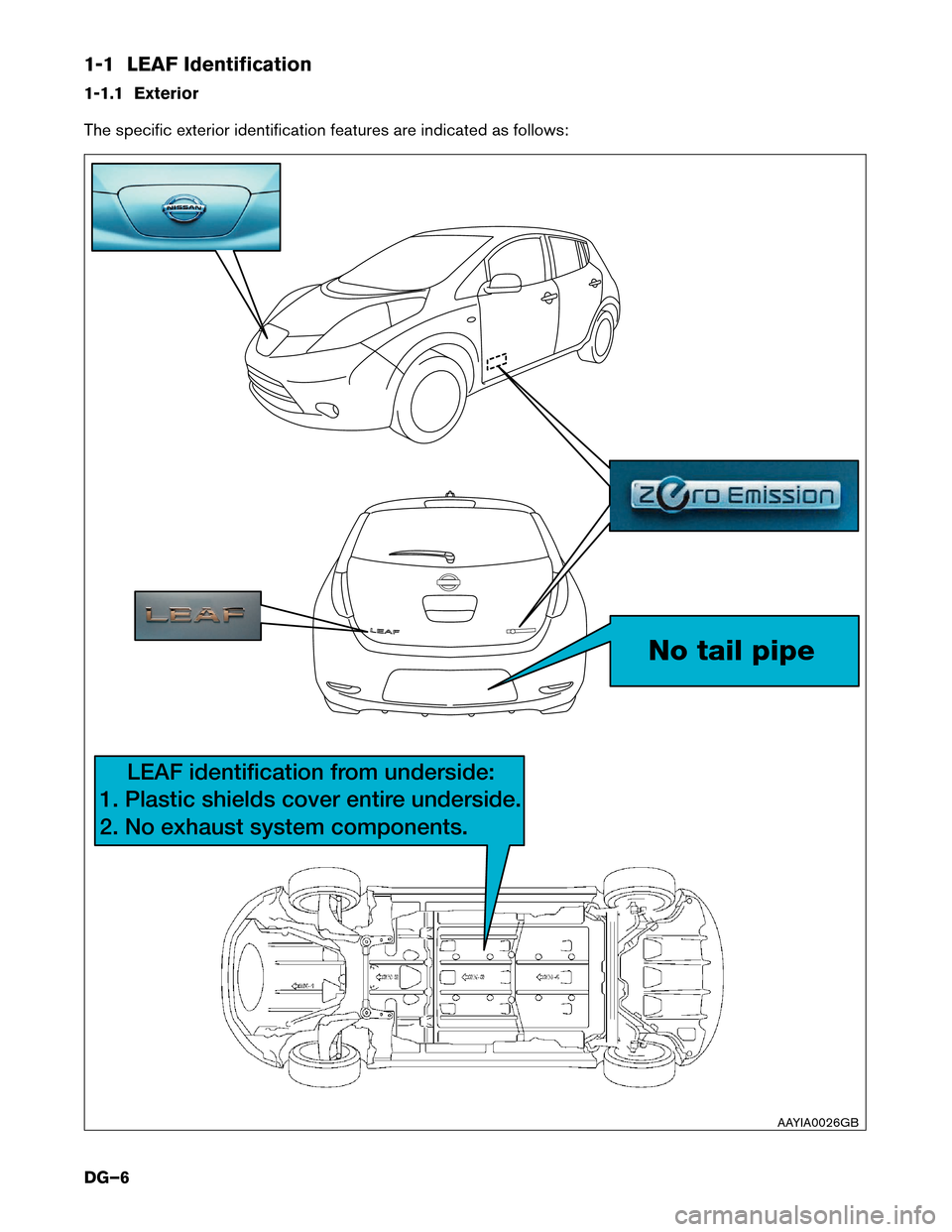
1-1 LEAF Identification
1-1.1
Exterior
The specific exterior identification features are indicated as follows: No tail pipe
LEAF identification from underside:
1. Plastic shields cover entir
e underside.
2. No exhaust system components.
AAYIA0026GB
DG–6
Page 7 of 45
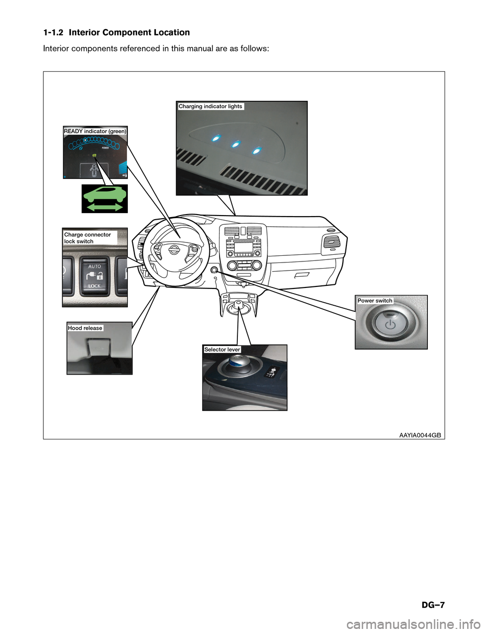
1-1.2 Interior Component Location
Interior
components referenced in this manual are as follows: Charging indicator lights
Power switch
Hood r
elease Selector lever
READY indicator (green)
Charge connector
lock switch
AAYIA0044GBDG–7
Page 8 of 45
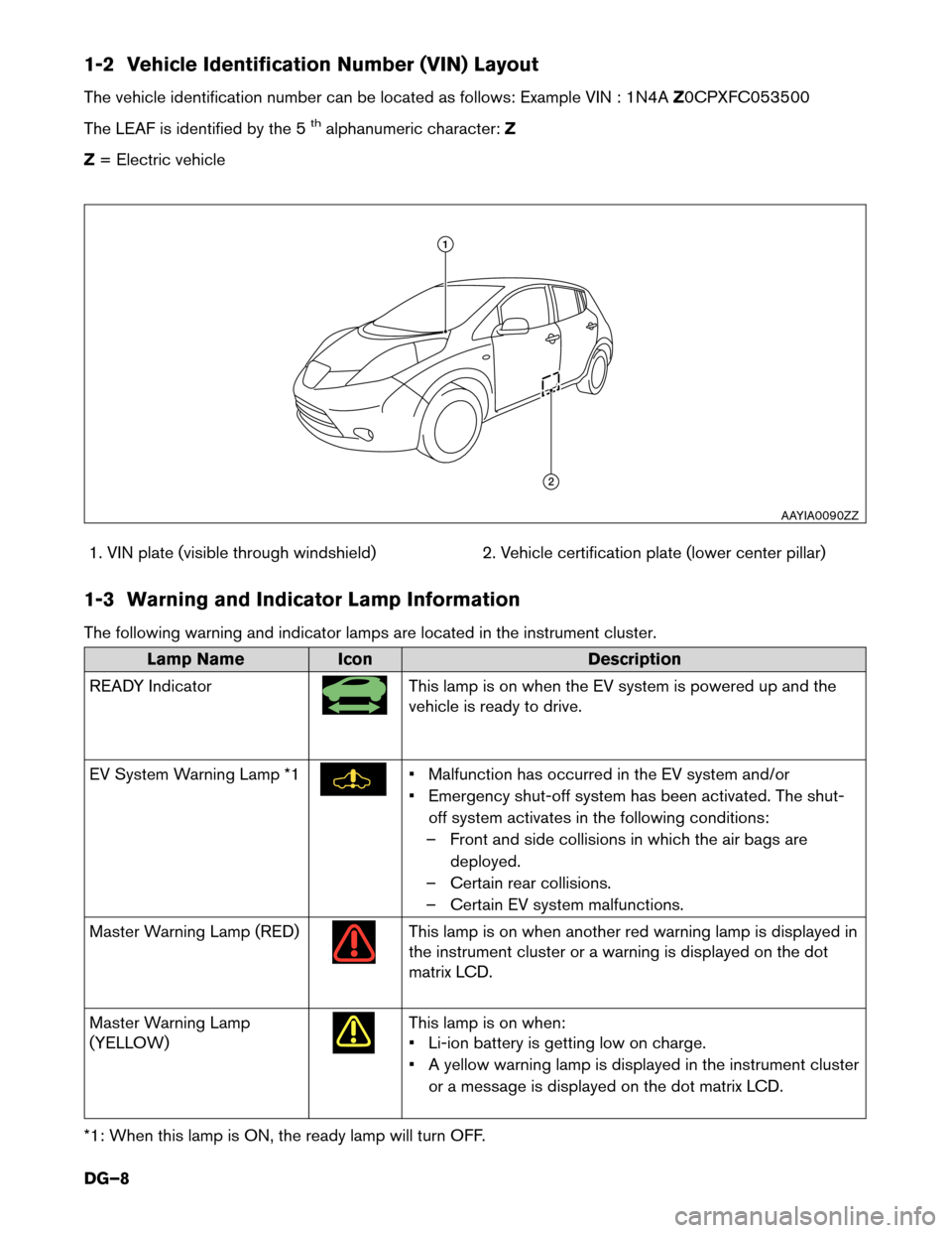
1-2 Vehicle Identification Number (VIN) Layout
The
vehicle identification number can be located as follows: Example VIN : 1N4A Z0CPXFC053500
The LEAF is identified by the 5
thalphanumeric character: Z
Z = Electric vehicle
1. VIN plate (visible through windshield) 2. Vehicle certification plate (lower center pillar)
1-3 Warning and Indicator Lamp Information
The following warning and indicator lamps are located in the instrument cluster. Lamp Name
Icon Description
READ
Y Indicator This lamp is on when the EV system is powered up and the
vehicle
is ready to drive.
EV System Warning Lamp *1 • Malfunction has occurred in the EV system and/or
•
Emergency shut-off system has been activated. The shut-
off system activates in the following conditions:
– Front and side collisions in which the air bags are deployed.
– Certain rear collisions.
– Certain EV system malfunctions.
Master Warning Lamp (RED) This lamp is on when another red warning lamp is displayed in
the
instrument cluster or a warning is displayed on the dot
matrix LCD.
Master Warning Lamp
(YELLOW) This lamp is on when:
•
Li-ion battery is getting low on charge.
• A yellow warning lamp is displayed in the instrument cluster or a message is displayed on the dot matrix LCD.
*1: When this lamp is ON, the ready lamp will turn OFF. 1
2
AAYIA0090ZZ
DG–8
Page 9 of 45
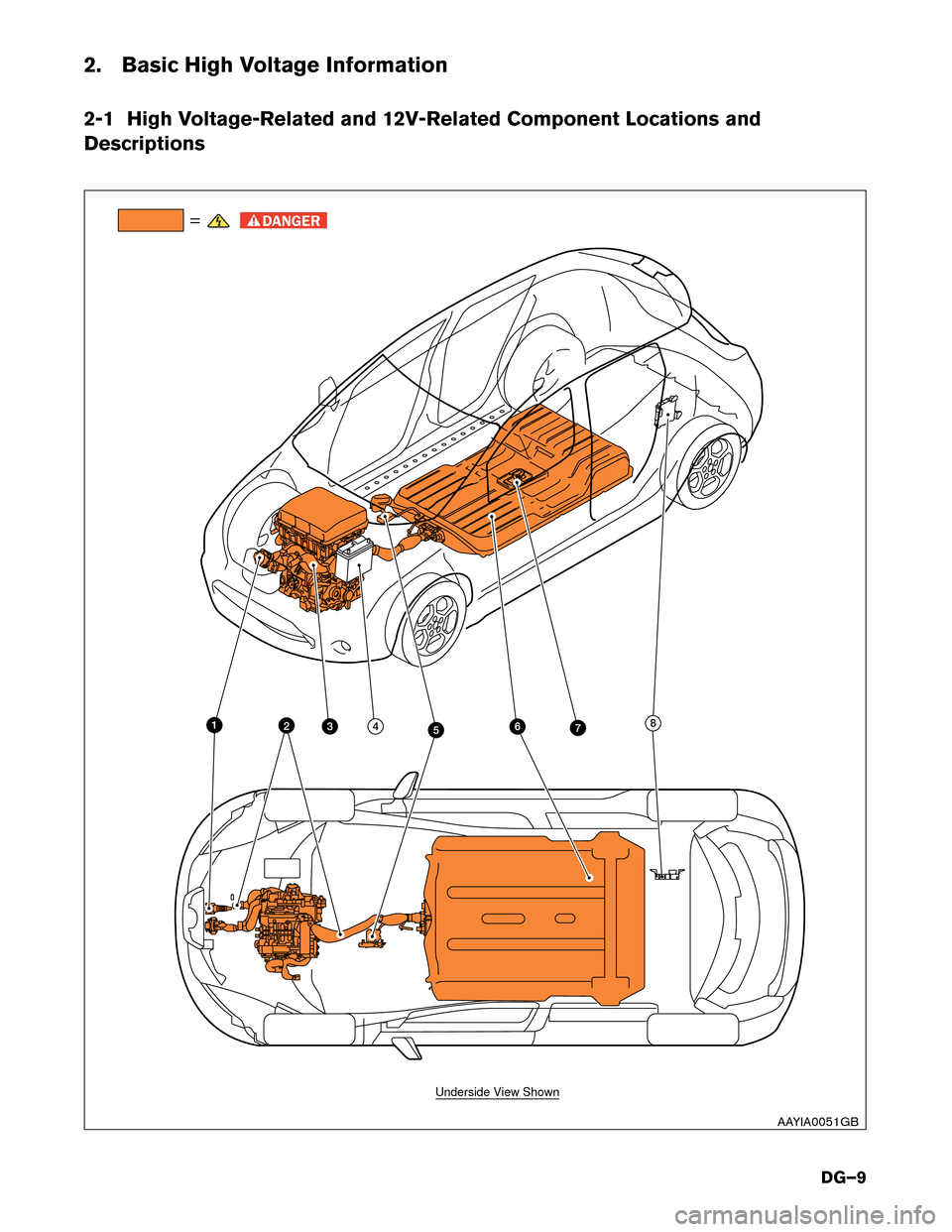
2. Basic High Voltage Information
2-1
High Voltage-Related and 12V-Related Component Locations and
Descriptions =
76
342 8
5 1
Underside View Shown
AAYIA0051GB
DG–9
Page 10 of 45
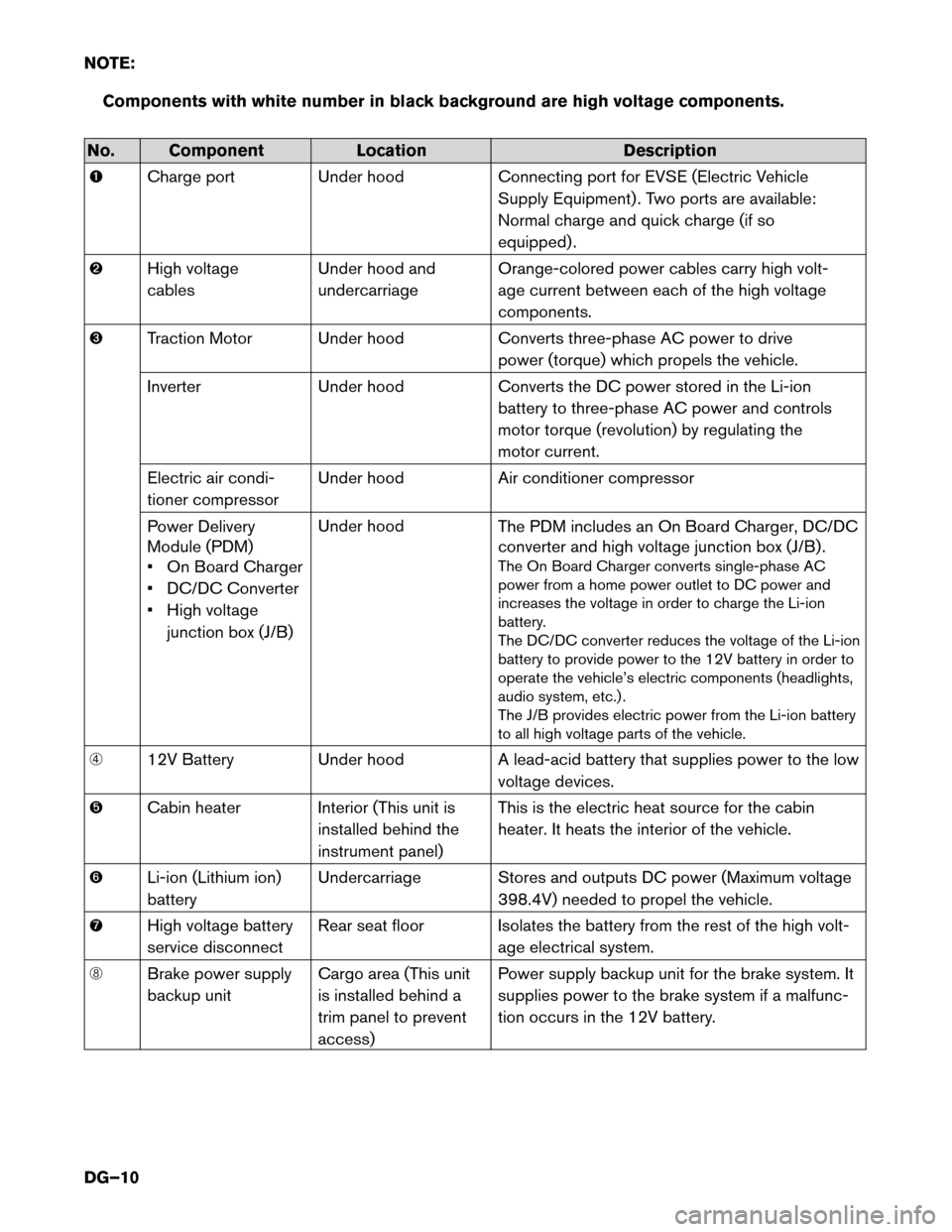
NOTE:
Components with white number in black background are high voltage components.No. Component
LocationDescription
� Charge
port Under hood Connecting port for EVSE (Electric Vehicle
Supply Equipment) . Two ports are available:
Normal charge and quick charge (if so
equipped) .
� High voltage
cables Under hood and
undercarriage Orange-colored power cables carry high volt-
age current between each of the high voltage
components.
� Traction Motor Under hood Converts three-phase AC power to drive
power (torque) which propels the vehicle.
Inverter Under hood Converts the DC power stored in the Li-ion
battery to three-phase AC power and controls
motor torque (revolution) by regulating the
motor current.
Electric air condi-
tioner compressor Under hood
Air conditioner compressor
Power Delivery
Module (PDM)
• On Board Charger
• DC/DC Converter
• High voltage junction box (J/B) Under hood
The PDM includes an On Board Charger, DC/DC
converter and high voltage junction box (J/B) .
The On Board Charger converts single-phase AC
power from a home power outlet to DC power and
increases the voltage in order to charge the Li-ion
battery.
The DC/DC converter reduces the voltage of the Li-ion
battery to provide power to the 12V battery in order to
operate the vehicle’s electric components (headlights,
audio system, etc.) .
The J/B provides electric power from the Li-ion battery
to all high voltage parts of the vehicle.
� 12V Battery Under hood A lead-acid battery that supplies power to the low
voltage devices.
� Cabin heater Interior (This unit is
installed behind the
instrument panel) This is the electric heat source for the cabin
heater. It heats the interior of the vehicle.
� Li-ion (Lithium ion)
battery Undercarriage Stores and outputs DC power (Maximum voltage
398.4V) needed to propel the vehicle.
� High voltage battery
service disconnect Rear seat floor Isolates the battery from the rest of the high volt-
age electrical system.
� Brake power supply
backup unit Cargo area (This unit
is installed behind a
trim panel to prevent
access) Power supply backup unit for the brake system. It
supplies power to the brake system if a malfunc-
tion occurs in the 12V battery.
DG–10