fuse NISSAN LEAF 2015 1.G Dismantling Guide
[x] Cancel search | Manufacturer: NISSAN, Model Year: 2015, Model line: LEAF, Model: NISSAN LEAF 2015 1.GPages: 45, PDF Size: 1.63 MB
Page 3 of 45
Table of Contents
FOREWORD
. . . . . . . . . . . . . . . . . . . . . . . . . . . . . . . . . . . . . . . . . . . . . . . . . . . . . . . . . . . . . . . . . . . . DG–2
NISSAN EMERGENCY CONTACT INFORMATION . . . . . . . . . . . . . . . . . . . . . . . . . . . . . . . . . . . DG–2
IMPORTANT INFORMATION ABOUT THIS MANUAL . . . . . . . . . . . . . . . . . . . . . . . . . . . . . . . . . . DG–2
1. ABOUT THE NISSAN LEAF® . . . . . . . . . . . . . . . . . . . . . . . . . . . . . . . . . . . . . . . . . . . . . . . . . . . . DG–5 1-1 LEAF IDENTIFICATION . . . . . . . . . . . . . . . . . . . . . . . . . . . . . . . . . . . . . . . . . . . . . . . . . . . . . DG–6 1-1.1 EXTERIOR . . . . . . . . . . . . . . . . . . . . . . . . . . . . . . . . . . . . . . . . . . . . . . . . . . . . . . . . . . DG–6
1-1.2 INTERIOR COMPONENT LOCATION . . . . . . . . . . . . . . . . . . . . . . . . . . . . . . . . . . . . . DG–7
1-2 VEHICLE IDENTIFICATION NUMBER (VIN) LAYOUT . . . . . . . . . . . . . . . . . . . . . . . . . . . . . . DG–8
1-3 WARNING AND INDICATOR LAMP INFORMATION . . . . . . . . . . . . . . . . . . . . . . . . . . . . . . DG–8
2. BASIC HIGH VOLTAGE INFORMATION . . . . . . . . . . . . . . . . . . . . . . . . . . . . . . . . . . . . . . . . . . . DG–9
2-1 HIGH VOLTAGE-RELATED AND 12V-RELATED COMPONENT LOCATIONS AND
DESCRIPTIONS . . . . . . . . . . . . . . . . . . . . . . . . . . . . . . . . . . . . . . . . . . . . . . . . . . . . . . . . . . . . . . DG–9 2-1.1 LI-ION BATTERY PACK SPECIFICATIONS . . . . . . . . . . . . . . . . . . . . . . . . . . . . . . . . DG–11
2-2 HIGH VOLTAGE SAFETY MEASURES . . . . . . . . . . . . . . . . . . . . . . . . . . . . . . . . . . . . . . . . DG–11 2-2.1 WARNING LABEL . . . . . . . . . . . . . . . . . . . . . . . . . . . . . . . . . . . . . . . . . . . . . . . . . . . DG–11
2-3 HIGH VOLTAGE CIRCUIT SHUT-OFF SYSTEM . . . . . . . . . . . . . . . . . . . . . . . . . . . . . . . . . DG–12
2-4 PREVENTING ELECTRICAL SHOCK . . . . . . . . . . . . . . . . . . . . . . . . . . . . . . . . . . . . . . . . . DG–12
3. PREPARATION FOR DISMANTLING . . . . . . . . . . . . . . . . . . . . . . . . . . . . . . . . . . . . . . . . . . . . . . DG–13
3-1 DISCHARGING PROCEDURES . . . . . . . . . . . . . . . . . . . . . . . . . . . . . . . . . . . . . . . . . . . . . DG–13
3-2 PREPARATION ITEMS . . . . . . . . . . . . . . . . . . . . . . . . . . . . . . . . . . . . . . . . . . . . . . . . . . . . DG–15
3-3 PERSONAL PROTECTIVE EQUIPMENT (PPE) AND INSULATED TOOLS . . . . . . . . . . . . . DG–163-3.1 PERSONAL PROTECTIVE EQUIPMENT (PPE) PROTECTIVE WEAR CONTROL . . DG–16
3-3.2 DAILY INSPECTION . . . . . . . . . . . . . . . . . . . . . . . . . . . . . . . . . . . . . . . . . . . . . . . . . DG–16
3-3.3 INSULATED TOOLS . . . . . . . . . . . . . . . . . . . . . . . . . . . . . . . . . . . . . . . . . . . . . . . . . DG–16
3-4 HIGH VOLTAGE SYSTEM SHUT-DOWN PROCEDURES . . . . . . . . . . . . . . . . . . . . . . . . . DG–16 3-4.1 REMOVING THE CHARGE CONNECTOR . . . . . . . . . . . . . . . . . . . . . . . . . . . . . . . . DG–18
3-4.2 INDICATIONS THE HIGH VOLTAGE SYSTEM IS ON . . . . . . . . . . . . . . . . . . . . . . . . DG–20
3-4.3 POWERING DOWN THE HIGH VOLTAGE SYSTEM . . . . . . . . . . . . . . . . . . . . . . . . DG–20
3-4.4 PRIMARY PROCEDURE . . . . . . . . . . . . . . . . . . . . . . . . . . . . . . . . . . . . . . . . . . . . . . DG–20
3-4.5 ALTERNATE PROCEDURE 1 (REMOVE FUSES) . . . . . . . . . . . . . . . . . . . . . . . . . . . DG–21
3-4.6 ALTERNATE PROCEDURE 2 (REMOVE SERVICE PLUG) . . . . . . . . . . . . . . . . . . . . DG–24
3-5 CUTTING THE VEHICLE BODY . . . . . . . . . . . . . . . . . . . . . . . . . . . . . . . . . . . . . . . . . . . . . DG–26 3-5.1 SRS AIR BAG SYSTEM COMPONENTS LOCATION . . . . . . . . . . . . . . . . . . . . . . . . DG–27
3-5.2 VEHICLE CUT SHEET . . . . . . . . . . . . . . . . . . . . . . . . . . . . . . . . . . . . . . . . . . . . . . . . DG–28
3-5.3 WATER SUBMERSION . . . . . . . . . . . . . . . . . . . . . . . . . . . . . . . . . . . . . . . . . . . . . . . DG–29
DG–3
Page 20 of 45
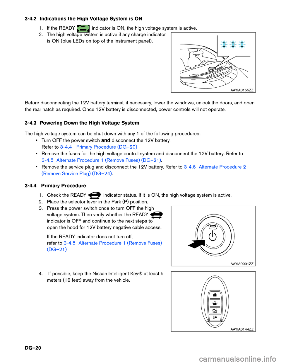
3-4.2 Indications the High Voltage System is ON
1. If the READY indicator is ON, the high voltage system is active.
2.
The high voltage system is active if any charge indicator
is ON (blue LEDs on top of the instrument panel) .
Before disconnecting the 12V battery terminal, if necessary, lower the windows, unlock the doors, and open
the rear hatch as required. Once 12V battery is disconnected, power controls will not operate.
3-4.3 Powering Down the High Voltage System
The high voltage system can be shut down with any 1 of the following procedures: • Turn OFF the power switch anddisconnect the 12V battery.
Refer to 3-4.4 Primary Procedure (DG–20) .
•
Remove the fuses for the high voltage control system and disconnect the 12V battery. Refer to
3-4.5 Alternate Procedure 1 (Remove Fuses) (DG–21).
•
Remove the service plug and disconnect the 12V battery. Refer to 3-4.6 Alternate Procedure 2
(Remove
Service Plug) (DG–24) .
3-4.4
Primary Procedure
1. Check the READY indicator status. If it is ON, the high voltage system is active.
2.
Place the selector lever in the Park (P) position.
3. Press the power switch once to turn OFF the high voltage system. Then verify whether the READY indicator is OFF and continue to the next steps to
open
the hood for 12V battery negative cable access.
If the READY indicator does not turn off,
refer to 3-4.5 Alternate Procedure 1 (Remove Fuses)
(DG–21)
4. If possible, keep the Nissan Intelligent Key® at least 5 meters
(16 feet) away from the vehicle. AAYIA0155ZZ
AAYIA0091ZZ
HOLD
AAYIA0144ZZ
DG–20
Page 21 of 45
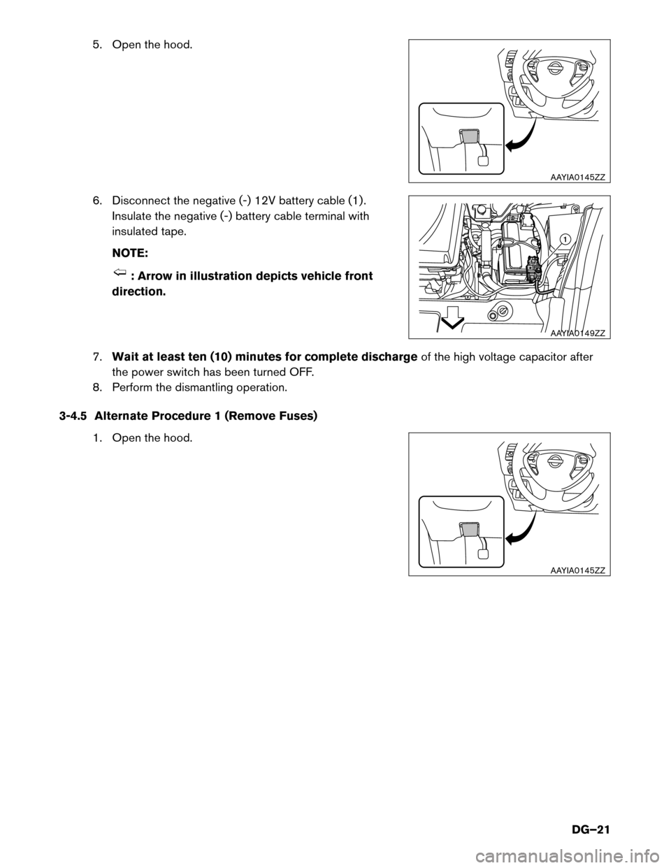
5. Open the hood.
6.
Disconnect the negative (-) 12V battery cable (1) .
Insulate the negative (-) battery cable terminal with
insulated tape.
NOTE: : Arrow in illustration depicts vehicle front
direction.
7. Wait
at least ten (10) minutes for complete discharge of the high voltage capacitor after
the power switch has been turned OFF.
8. Perform the dismantling operation.
3-4.5 Alternate Procedure 1 (Remove Fuses) 1. Open the hood. AAYIA0145ZZ
1
AAYIA0149ZZ AAYIA0145ZZ
DG–21
Page 22 of 45
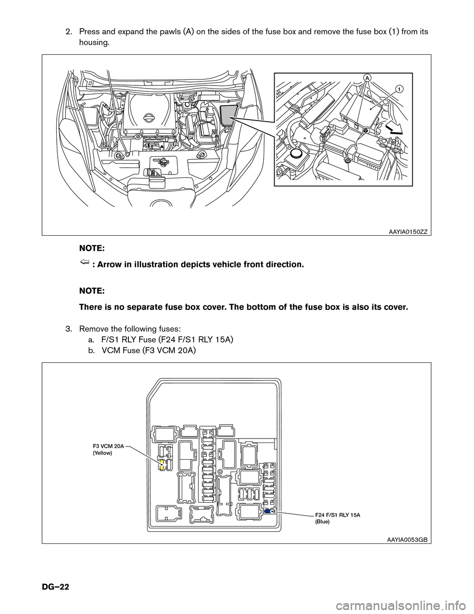
2. Press and expand the pawls (A) on the sides of the fuse box and remove the fuse box (1) from its
housing.
NO
TE: : Arrow in illustration depicts vehicle front direction.
NO
TE:
There is no separate fuse box cover. The bottom of the fuse box is also its cover.
3. Remove the following fuses: a. F/S1 RLY Fuse (F24 F/S1 RLY 15A)
b. VCM Fuse (F3 VCM 20A) 1A
AAYIA0150ZZ
F24 F/S1 RLY 15A
(Blue)F3 VCM 20A
(Y
ellow)
AAYIA0053GB
DG–22
Page 23 of 45
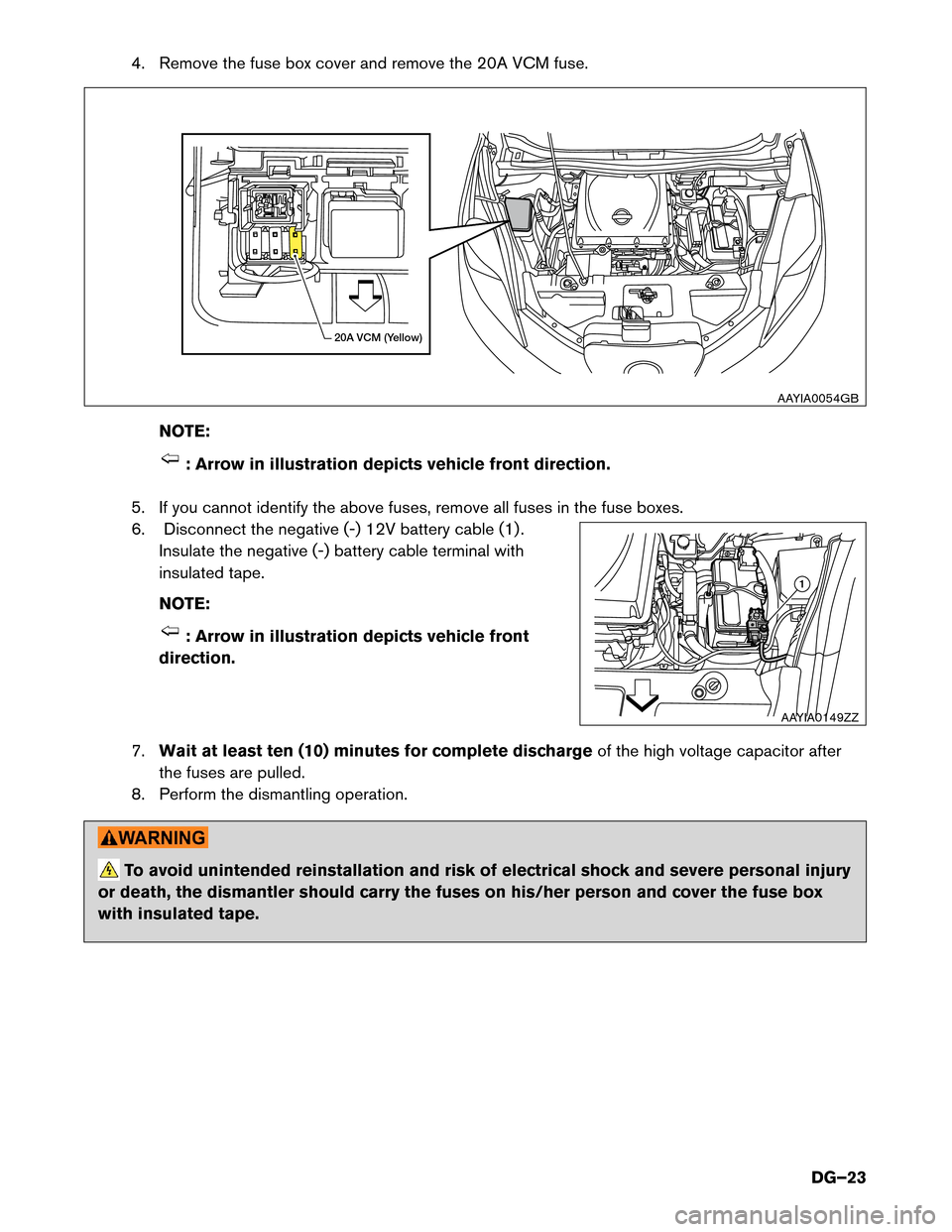
4. Remove the fuse box cover and remove the 20A VCM fuse.
NO TE: : Arrow in illustration depicts vehicle front direction.
5.
If you cannot identify the above fuses, remove all fuses in the fuse boxes.
6. Disconnect the negative (-) 12V battery cable (1) . Insulate the negative (-) battery cable terminal with
insulated tape.
NOTE: : Arrow in illustration depicts vehicle front
direction.
7. Wait
at least ten (10) minutes for complete discharge of the high voltage capacitor after
the fuses are pulled.
8. Perform the dismantling operation. To avoid unintended reinstallation and risk of electrical shock and severe personal injury
or
death, the dismantler should carry the fuses on his/her person and cover the fuse box
with insulated tape. 20A VCM (Yellow)
AAYIA0054GB 1
AAYIA0149ZZ
DG–23
Page 26 of 45
3-5 Cutting the Vehicle Body
• Do not cut into high voltage related areas to avoid severe personal injury or death.
• Do not cut into the Li-ion battery to avoid severe personal injury or death.
• When removing parts, NEVER touch the high voltage parts or the insides of the
exposed orange-colored high voltage cables to avoid severe personal injury or death.
Personal Protective Equipment (PPE) must always be worn when touching or
working on high voltage components. • To avoid unintended reinstallation and risk of electrical shock and severe personal injury
or
death, the dismantler should carry the fuses or service plug on his/her person while
work is in progress.
• Do not cut air bag parts to avoid unintended deployment of the air bags and the risk of severe personal injury or death.
If at least ten (10) minutes have passed since the dismantler shut down the high voltage system (refer to
3-4 High Voltage System Shut-Down Procedures (DG–16)) , then the dismantler can cut the vehicle
except
for the Li-ion battery. DO NOT cut the Li-ion battery due to possible electrocution risk and electrolyte solution
leakage.
DG–26
Page 33 of 45
12. If necessary, connect the vehicle to a charging station or EVSE (Electric Vehicle Supply
Equipment) to charge the Li-ion battery. The vehicle cannot be driven unless the Li-ion battery is
charged.
NOTE:
If it is not possible to turn the LEAF system ON by following this procedure, contact a
NISSAN certified LEAF dealer immediately.
4-2 P (Park) Position Release Procedure
If you need to release the vehicle from the P (Park) position, proceed as follows. When power switch is
turned OFF or 12V battery is low, LEAF automatically shifts to P position.
NOTE: This procedure requires two (2) people.
1. To start the EV system with a booster battery, refer to 4. Jump Starting (DG–31).
2.
Turn power switch ON by pushing the power switch 2 times without pressing brake pedal.
3. Confirm parking brake is applied.
4. Close all doors and press and hold the brake pedal.
5. Place the selector lever in the N (Neutral) position.
6. Remove the following 2 fuses:
• F/L 40A PBW MTR (under hood fuse and relay box)
• METER 1 10A (in the cabin fuse box)
DG–33
Page 34 of 45
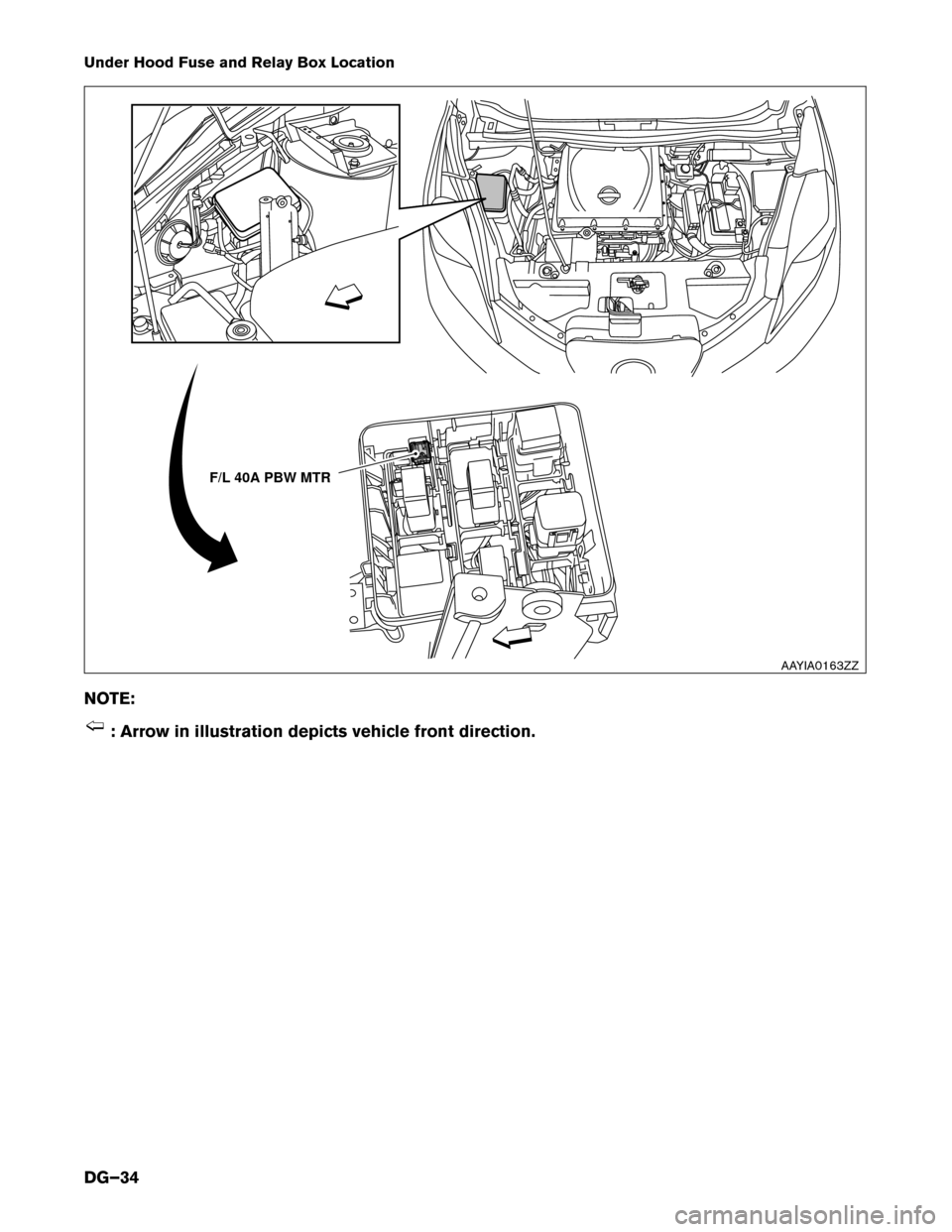
Under Hood Fuse and Relay Box Location
NO
TE: : Arrow in illustration depicts vehicle front direction. F/L 40A PBW MTR
AAYIA0163ZZ
DG–34
Page 35 of 45
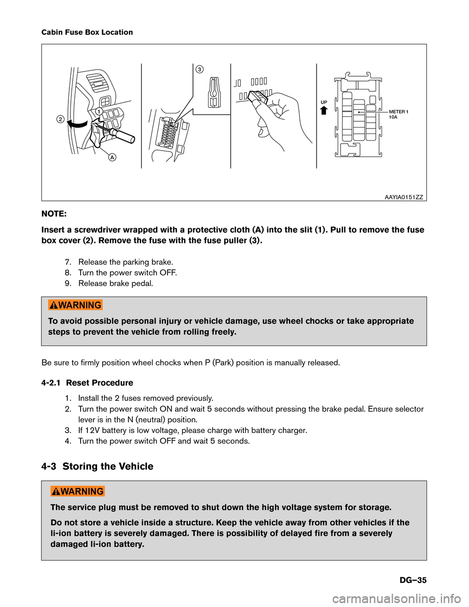
Cabin Fuse Box Location
NO
TE:
Insert a screwdriver wrapped with a protective cloth (A) into the slit (1) . Pull to remove the fuse
box cover (2) . Remove the fuse with the fuse puller (3) .
7. Release the parking brake.
8. Turn the power switch OFF.
9. Release brake pedal. To avoid possible personal injury or vehicle damage, use wheel chocks or take appropriate
steps
to prevent the vehicle from rolling freely.
Be sure to firmly position wheel chocks when P (Park) position is manually released.
4-2.1 Reset Procedure 1. Install the 2 fuses removed previously.
2. Turn the power switch ON and wait 5 seconds without pressing the brake pedal. Ensure selectorlever is in the N (neutral) position.
3. If 12V battery is low voltage, please charge with battery charger.
4. Turn the power switch OFF and wait 5 seconds.
4-3 Storing the Vehicle The service plug must be removed to shut down the high voltage system for storage.
Do
not store a vehicle inside a structure. Keep the vehicle away from other vehicles if the
li-ion battery is severely damaged. There is possibility of delayed fire from a severely
damaged li-ion battery. UP
METER 1
10A
11 3
2
A
AAYIA0151ZZ
DG–35