warning NISSAN LEAF 2015 1.G Roadside Assistance Guide
[x] Cancel search | Manufacturer: NISSAN, Model Year: 2015, Model line: LEAF, Model: NISSAN LEAF 2015 1.GPages: 39, PDF Size: 1.16 MB
Page 2 of 39
Foreword
This
manual describes roadside assistance operations and related warnings for this vehicle.
This vehicle is an electrically driven car equipped with a high voltage battery pack. Failure to follow
recommended practices during emergency responses will cause death or serious personal
injury.
Please read this manual in advance in order to understand the features of this vehicle and to help you deal
with roadside assistance operations involving this vehicle. Follow the procedures in order to help assure
a safe and successful roadside assistance operation.
This manual is periodically updated. If you are not viewing this manual on the Nissan web site, we urge you
to go to www.nissanusa.com orwww.nissan-techinfo.com to make sure you have the most recent version of
this
manual.
NISSAN EMERGENCY CONTACT INFORMATION • Nissan EV Customer Support: 1-877-664-2738 (Hours of operation are Monday-Friday 7am -7pm, Saturday 8am - 4:30pm Central time zone)
• Nissan Consumer Affairs: 1-800-647-7261 (US) or 1-800-387-0122 (Canada) (Hours of operation are 8am - 5pm (Monday-Friday) Eastern, Central and Pacific time zones)
IMPORTANT INFORMATION ABOUT THIS MANUAL
You may see various symbols in this manual. They have the following meanings: This symbol is used to inform you of an operation which will result in death or serious personal injury if
instructions
are not followed.
Example: Touching high voltage components without using the appropriate protective equipment will result
in electrocution. This symbol is used to inform you of an operation which may cause death or serious personal injury if
instructions
are not followed.This symbol is used to inform you of an operation which may cause personal injury or component damage if
instructions
are not followed.
Please note that there may be differences between this manual and the vehicle specification due to
specification changes.
RAG–2
Page 3 of 39
Table of Contents
FOREWORD
. . . . . . . . . . . . . . . . . . . . . . . . . . . . . . . . . . . . . . . . . . . . . . . . . . . . . . . . . . . . . . . . . . RAG–2
NISSAN EMERGENCY CONTACT INFORMATION . . . . . . . . . . . . . . . . . . . . . . . . . . . . . . . . . . RAG–2
IMPORTANT INFORMATION ABOUT THIS MANUAL . . . . . . . . . . . . . . . . . . . . . . . . . . . . . . . . RAG–2
1. ABOUT THE NISSAN LEAF® . . . . . . . . . . . . . . . . . . . . . . . . . . . . . . . . . . . . . . . . . . . . . . . . . . . RAG–5
1-1 LEAF IDENTIFICATION . . . . . . . . . . . . . . . . . . . . . . . . . . . . . . . . . . . . . . . . . . . . . . . . . . . . RAG–6 1-1.1 EXTERIOR . . . . . . . . . . . . . . . . . . . . . . . . . . . . . . . . . . . . . . . . . . . . . . . . . . . . . . . . . RAG–6
1-1.2 INTERIOR COMPONENT LOCATION . . . . . . . . . . . . . . . . . . . . . . . . . . . . . . . . . . . RAG–7
1-1.3 VEHICLE IDENTIFICATION NUMBER (VIN) LAYOUT . . . . . . . . . . . . . . . . . . . . . . . . RAG–8
1-1.4 WARNING AND INDICATOR LAMP INFORMATION . . . . . . . . . . . . . . . . . . . . . . . . RAG–8
2. BASIC HIGH VOLTAGE INFORMATION . . . . . . . . . . . . . . . . . . . . . . . . . . . . . . . . . . . . . . . . . . RAG–9 2-1 HIGH VOLTAGE-RELATED AND 12V-RELATED COMPONENT LOCATIONS AND
DESCRIPTIONS . . . . . . . . . . . . . . . . . . . . . . . . . . . . . . . . . . . . . . . . . . . . . . . . . . . . . . . . . . . . . RAG–9 2-1.1 LI-ION BATTERY PACK SPECIFICATIONS . . . . . . . . . . . . . . . . . . . . . . . . . . . . . . RAG–11
2-2 HIGH VOLTAGE SAFETY MEASURES . . . . . . . . . . . . . . . . . . . . . . . . . . . . . . . . . . . . . . . RAG–11 2-2.1 WARNING LABEL . . . . . . . . . . . . . . . . . . . . . . . . . . . . . . . . . . . . . . . . . . . . . . . . . . RAG–11
3. ROADSIDE ASSISTANCE RESPONSE STEPS . . . . . . . . . . . . . . . . . . . . . . . . . . . . . . . . . . . . RAG–12
3-1 INDICATIONS THE HIGH VOLTAGE SYSTEM IS ON . . . . . . . . . . . . . . . . . . . . . . . . . . . RAG–12
3-2 VEHICLE IMMOBILIZATION AND STABILIZATION . . . . . . . . . . . . . . . . . . . . . . . . . . . . . . RAG–13
3-3 TURNING OFF THE POWER SWITCH . . . . . . . . . . . . . . . . . . . . . . . . . . . . . . . . . . . . . . RAG–14
3-4 WATER SUBMERSION . . . . . . . . . . . . . . . . . . . . . . . . . . . . . . . . . . . . . . . . . . . . . . . . . . . RAG–14
3-5 VEHICLE FIRE . . . . . . . . . . . . . . . . . . . . . . . . . . . . . . . . . . . . . . . . . . . . . . . . . . . . . . . . . . RAG–15
3-6 LI-ION BATTERY DAMAGE AND FLUID LEAKS . . . . . . . . . . . . . . . . . . . . . . . . . . . . . . . . RAG–16
4. ROADSIDE ASSISTANCE . . . . . . . . . . . . . . . . . . . . . . . . . . . . . . . . . . . . . . . . . . . . . . . . . . . . . RAG–17 4-1 JUMP STARTING . . . . . . . . . . . . . . . . . . . . . . . . . . . . . . . . . . . . . . . . . . . . . . . . . . . . . . . RAG–174-1.1 JUMP STARTING PROCEDURES . . . . . . . . . . . . . . . . . . . . . . . . . . . . . . . . . . . . . RAG–18
4-2 P (PARK) POSITION RELEASE PROCEDURE . . . . . . . . . . . . . . . . . . . . . . . . . . . . . . . . . RAG–19 4-2.1 RESET PROCEDURE . . . . . . . . . . . . . . . . . . . . . . . . . . . . . . . . . . . . . . . . . . . . . . . RAG–21
4-3 TOWING . . . . . . . . . . . . . . . . . . . . . . . . . . . . . . . . . . . . . . . . . . . . . . . . . . . . . . . . . . . . . . RAG–22 4-3.1 VEHICLE SPECIFICATIONS . . . . . . . . . . . . . . . . . . . . . . . . . . . . . . . . . . . . . . . . . . RAG–22
4-3.2 TOWING GUIDELINES . . . . . . . . . . . . . . . . . . . . . . . . . . . . . . . . . . . . . . . . . . . . . . RAG–22
4-3.3 USE OF VEHICLE EQUIPPED HOOKS FOR RECOVERY OPERATIONS . . . . . . . RAG–24
4-4 STORING THE VEHICLE . . . . . . . . . . . . . . . . . . . . . . . . . . . . . . . . . . . . . . . . . . . . . . . . . RAG–26
4-5 JACKING UP THE VEHICLE AND CHANGING A TIRE . . . . . . . . . . . . . . . . . . . . . . . . . . RAG–26
RAG–3
Page 8 of 39
1-1.3 Vehicle Identification Number (VIN) Layout
The
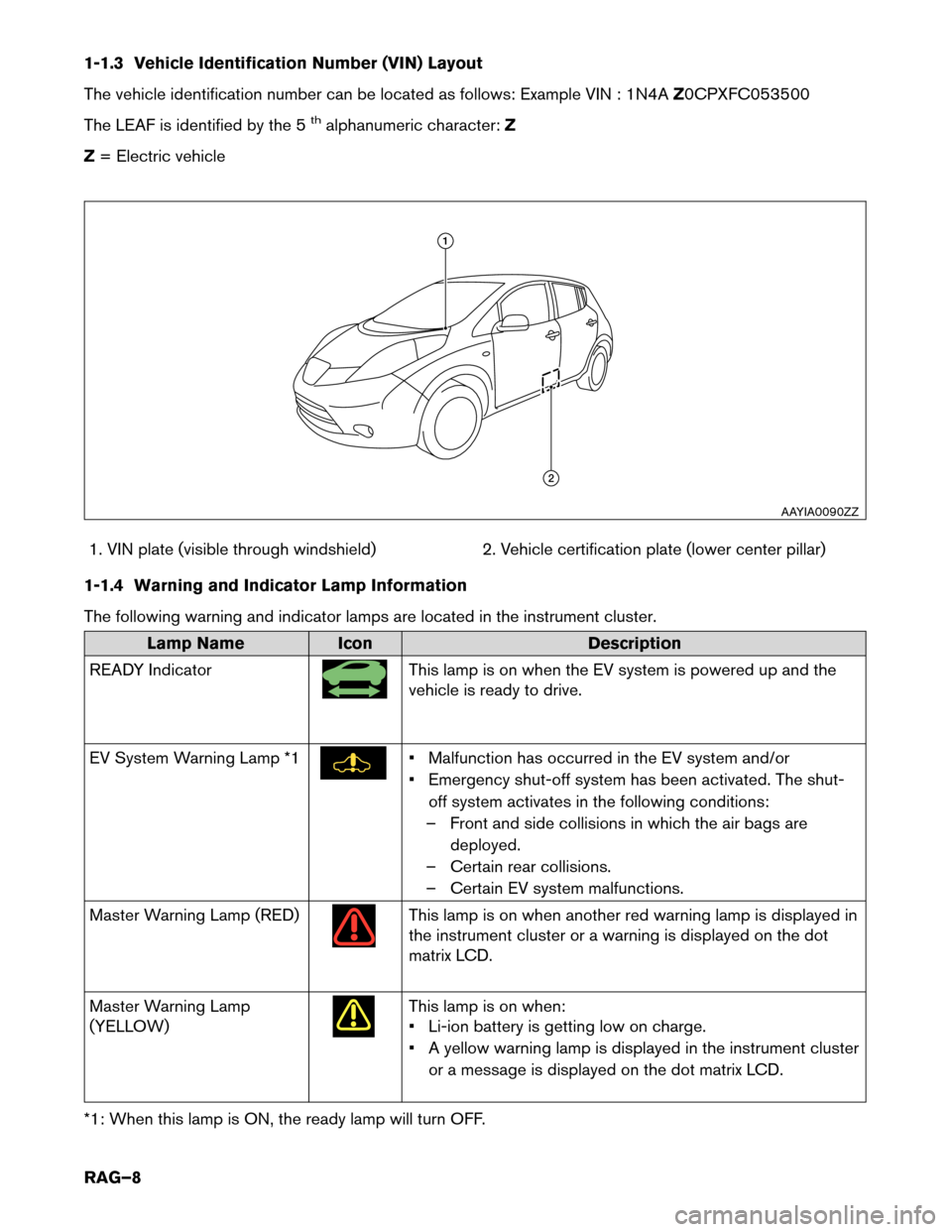
vehicle identification number can be located as follows: Example VIN : 1N4A Z0CPXFC053500
The LEAF is identified by the 5
thalphanumeric character: Z
Z = Electric vehicle
1. VIN plate (visible through windshield) 2. Vehicle certification plate (lower center pillar)
1-1.4 Warning and Indicator Lamp Information
The following warning and indicator lamps are located in the instrument cluster. Lamp Name
Icon Description
READ
Y Indicator This lamp is on when the EV system is powered up and the
vehicle
is ready to drive.
EV System Warning Lamp *1 • Malfunction has occurred in the EV system and/or
•
Emergency shut-off system has been activated. The shut-
off system activates in the following conditions:
– Front and side collisions in which the air bags are deployed.
– Certain rear collisions.
– Certain EV system malfunctions.
Master Warning Lamp (RED) This lamp is on when another red warning lamp is displayed in
the
instrument cluster or a warning is displayed on the dot
matrix LCD.
Master Warning Lamp
(YELLOW) This lamp is on when:
•
Li-ion battery is getting low on charge.
• A yellow warning lamp is displayed in the instrument cluster or a message is displayed on the dot matrix LCD.
*1: When this lamp is ON, the ready lamp will turn OFF. 1
2
AAYIA0090ZZ
RAG–8
Page 11 of 39
2-1.1 Li-ion Battery Pack Specifications
Li-ion battery voltage
360V nominal
(240V - 398.4V usable range)
Number of Li-ion battery modules in the pack 48
Li-ion battery dimensions 60.91 x 46.77 x 10.39 in. (1547 x 1188 x 264 mm)
Li-ion battery weight 606 lbs (275 kg)
2-2 High Voltage Safety Measures Circuit insulation
The high voltage positive (+) and negative (-) circuits are insulated
from
the metal chassis.
Reducing the risk of electrocution The high voltage components and harnesses have insulated cases or orange-colored coverings which provide insulation and easy
identification.
The high voltage battery case is electrically connected to the vehicle ground.
This connection helps protect the vehicle occupants and emergency
responders from high voltage electrical shock.
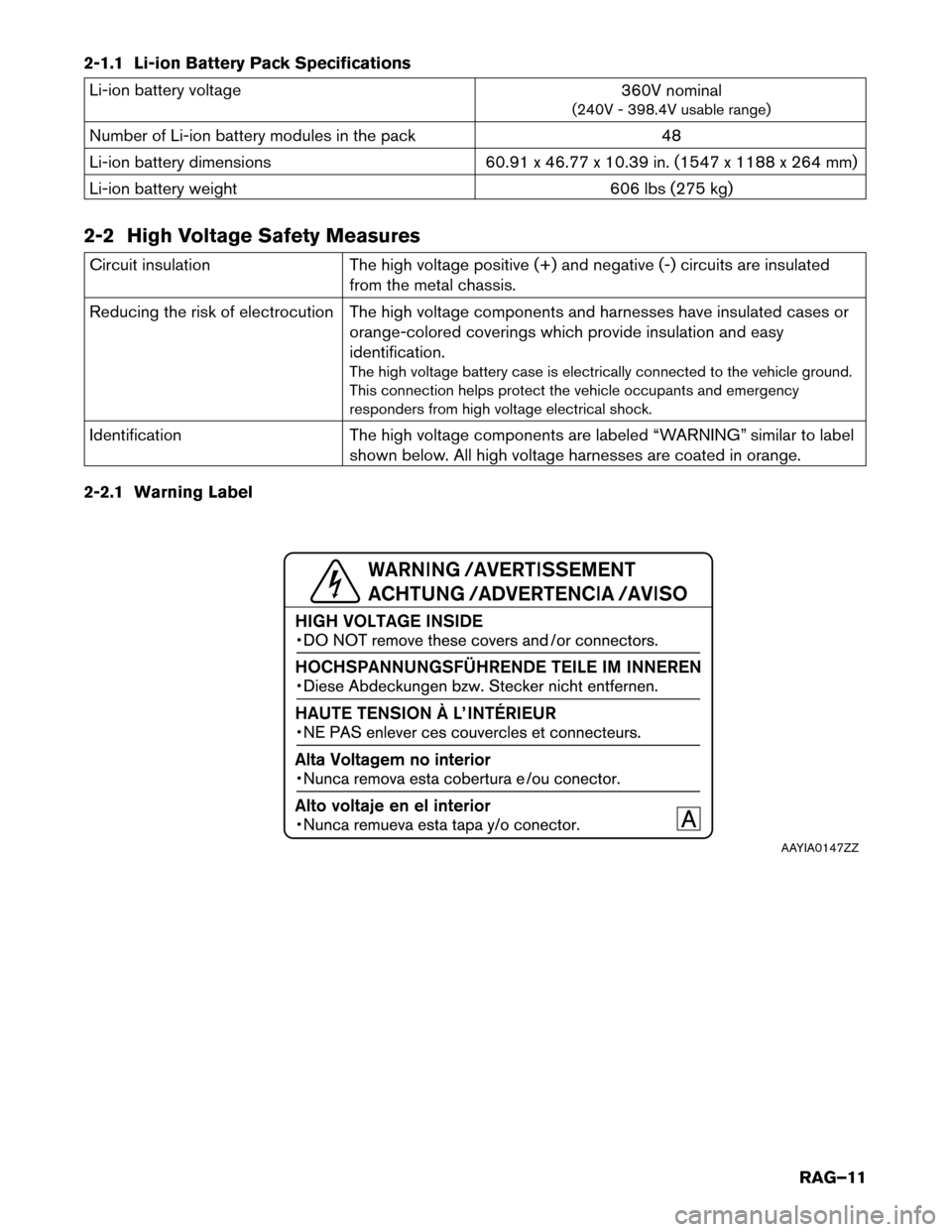
Identification The high voltage components are labeled “WARNING” similar to label
shown below. All high voltage harnesses are coated in orange.
2-2.1 Warning Label AAYIA0147ZZ
RAG–11
Page 28 of 39
4-6 Repairing a Flat Tire with Nissan Emergency Tire Puncture Repair Kit
LEAF
is equipped with a tire repair kit as standard equipment. It is intended to be used to temporarily repair
minor tire punctures. • After using the Emergency Tire Sealant to repair a minor tire puncture, do not drive the
vehicle
at speeds faster than 50 MPH (80 km/h) .
• Immediately after using the Emergency Tire Sealant to repair a minor tire puncture, take the vehicle to a NISSAN certified LEAF dealer to inspect, and repair or replace the tire.
The Emergency Tire Sealant cannot permanently seal a punctured tire. Continuing
operation of the vehicle without a permanent tire repair can lead to a crash.
• If you used the Emergency Tire Sealant to repair a minor tire puncture, a NISSAN certified LEAF dealer will also need to replace the TPMS sensor in addition to repairing or
replacing the tire.
• Nissan recommends using only NISSAN Genuine Emergency Tire Sealant provided with the vehicle. Other tire sealants may damage the valve stem seal which can cause the
tire to lose air pressure.
• Make sure the parking brake is applied.
• Turn the power switch OFF while using the Emergency Tire Sealant to repair a flat tire.
• Have all passengers get out of the vehicle and stand in a safe place away from traffic and clear of the vehicle.
• Make sure the vehicle is located safely away from oncoming traffic and other hazards.
• Observe the following precautions when using the tire repair compound:
– Swallowing the compound is dangerous. Immediately drink as much water as possible and seek prompt medical assistance.
– Rinse well with lots of water if the compound comes into contact with skin or eyes. If irritation persists, seek prompt medical attention.
– Keep the repair compound out of the reach of children.
– The emergency repair compound may cause a malfunction of the tire pressure sensors and cause the low tire pressure warning light to illuminate. Have the tire pressure
sensor replaced as soon as possible.
RAG–28
Page 30 of 39
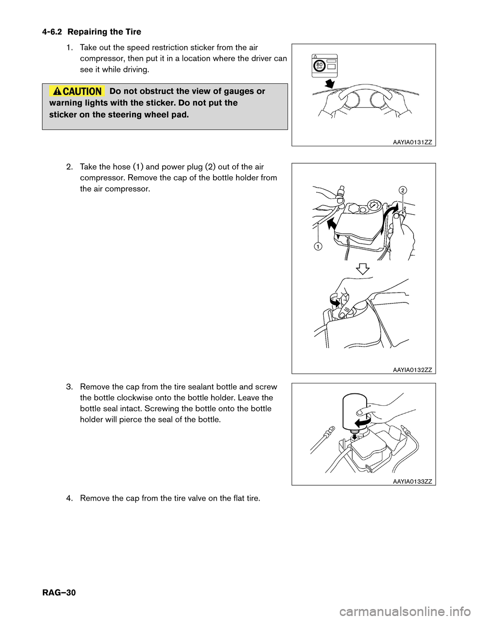
4-6.2 Repairing the Tire
1. Take out the speed restriction sticker from the air
compressor, then put it in a location where the driver can
see it while driving. Do not obstruct the view of gauges or
warning
lights with the sticker. Do not put the
sticker on the steering wheel pad.
2. Take the hose (1) and power plug (2) out of the aircompressor. Remove the cap of the bottle holder from
the air compressor.
3. Remove the cap from the tire sealant bottle and screw the bottle clockwise onto the bottle holder. Leave the
bottle seal intact. Screwing the bottle onto the bottle
holder will pierce the seal of the bottle.
4. Remove the cap from the tire valve on the flat tire. AAYIA0131ZZ
2
1
AAYIA0132ZZ AAYIA0133ZZ
RAG–30