ABS NISSAN MAXIMA 2005 A34 / 6.G Owners Manual
[x] Cancel search | Manufacturer: NISSAN, Model Year: 2005, Model line: MAXIMA, Model: NISSAN MAXIMA 2005 A34 / 6.GPages: 288, PDF Size: 4.71 MB
Page 25 of 288

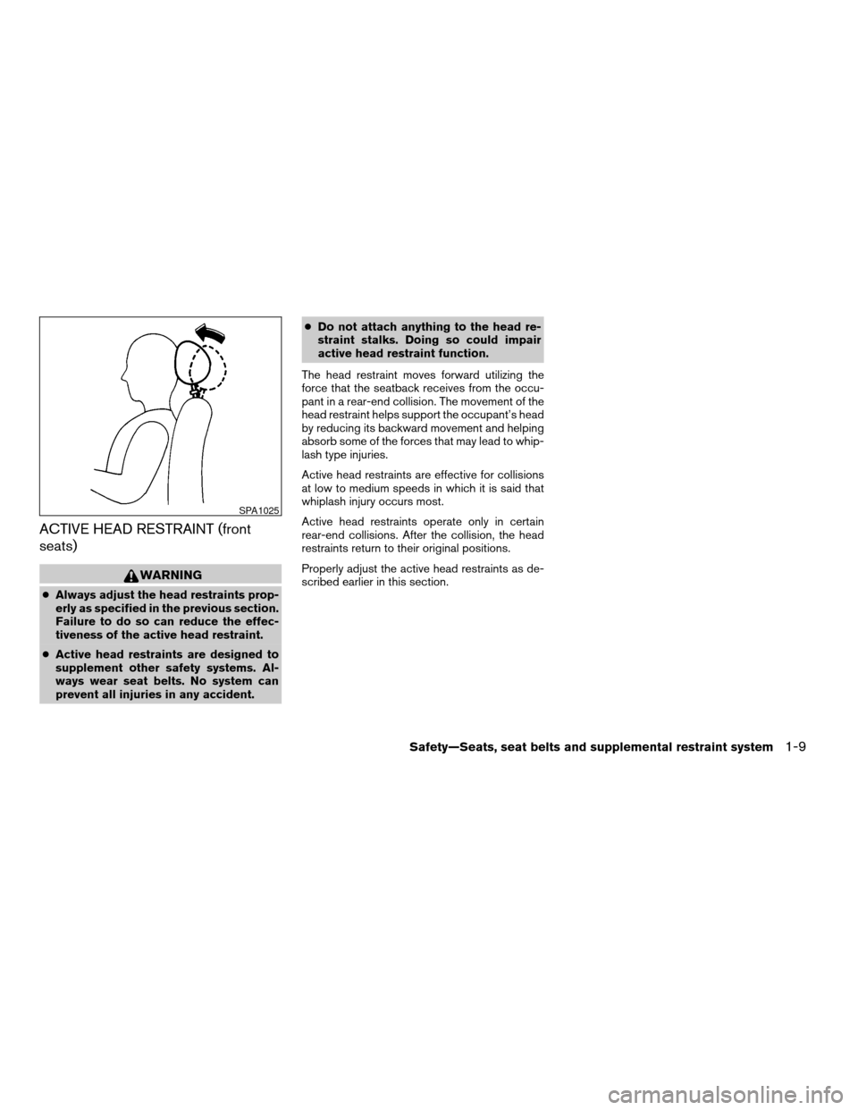
ACTIVE HEAD RESTRAINT (front
seats)
WARNING
cAlways adjust the head restraints prop-
erly as specified in the previous section.
Failure to do so can reduce the effec-
tiveness of the active head restraint.
cActive head restraints are designed to
supplement other safety systems. Al-
ways wear seat belts. No system can
prevent all injuries in any accident.cDo not attach anything to the head re-
straint stalks. Doing so could impair
active head restraint function.
The head restraint moves forward utilizing the
force that the seatback receives from the occu-
pant in a rear-end collision. The movement of the
head restraint helps support the occupant’s head
by reducing its backward movement and helping
absorb some of the forces that may lead to whip-
lash type injuries.
Active head restraints are effective for collisions
at low to medium speeds in which it is said that
whiplash injury occurs most.
Active head restraints operate only in certain
rear-end collisions. After the collision, the head
restraints return to their original positions.
Properly adjust the active head restraints as de-
scribed earlier in this section.
SPA1025
Safety—Seats, seat belts and supplemental restraint system1-9
ZREVIEW COPYÐ2005 Maxima(max)
Owners ManualÐUSA_English(nna)
09/01/04Ðtbrooks
X
Page 171 of 288

5 Starting and driving
Precautions when starting and driving................5-2
Exhaust gas (carbon monoxide)..................5-2
Three-way catalyst..............................5-2
Avoiding collision and rollover....................5-3
Drinking alcohol/drugs and driving................5-3
Ignition switch.....................................5-4
Automatic transmission..........................5-4
Manual transmission............................5-5
Key positions..................................5-5
Nissan vehicle immobilizer system (NVIS).........5-5
Before starting the engine..........................5-6
Starting the engine................................5-6
Driving the vehicle.................................5-7
Automatic transmission (if so equipped)...........5-7
Manual transmission...........................5-11
Parking brake....................................5-12
Cruise control (if so equipped).....................5-13
Precautions on cruise control...................5-13
Cruise control operations.......................5-13Break-in schedule................................5-14
Increasing fuel economy...........................5-15
Parking/parking on hills............................5-16
Power steering...................................5-17
Brake system....................................5-17
Brake precautions.............................5-17
Anti-lock brake system (ABS)...................5-18
Traction control system (TCS) (if so equipped).......5-19
Vehicle dynamic control (VDC) system
(if so equipped)..................................5-20
Cold weather driving..............................5-21
Freeing a frozen door lock......................5-21
Anti-freeze....................................5-21
Battery.......................................5-21
Draining of coolant water.......................5-21
Tire equipment................................5-22
Special winter equipment.......................5-22
Driving on snow or ice.........................5-23
Engine block heater (if so equipped).............5-23
ZREVIEW COPYÐ2005 Maxima(max)
Owners ManualÐUSA_English(nna)
09/01/04Ðtbrooks
X
Page 188 of 288

This procedure is described in the vehicle service
manual and can be performed by a NISSAN
dealer.
ANTI-LOCK BRAKE SYSTEM (ABS)
The anti-lock brake system controls the brakes so
the wheels do not lock when braking abruptly or
when braking on slippery surfaces. The system
detects the rotation speed at each wheel and
varies the brake fluid pressure to prevent each
wheel from locking and sliding. By preventing
wheel lockup, the system helps the driver main-
tain steering control and helps to minimize swerv-
ing and spinning on slippery surfaces.
Using the system
Depress the brake pedal and hold it down.
WARNING
Do not pump the brake pedal. Doing so
may result in increased stopping
distances.
Normal operation
The anti-lock brake system does not operate at
speeds below3-6MPH(5-10km/h) . (The
speeds vary according to road conditions.)
When driving, the anti-lock brake system con-
trols the wheels so they will not lock when brak-ing abruptly or when braking on a slippery road.
Thus, difficult steering and swerving of the ve-
hicle due to locked wheels is minimized. The
system detects the wheel rotation rate and elec-
tronically controls the pressure applied to each
brake. Slight vibration on the brake pedal accom-
panied by noise usually occurs while the ABS
system is operating. Such vibration and noise
encountered during abrupt braking is not a prob-
lem, but indicates that the system is functioning
properly. However, the pulsation may indicate
that road conditions are hazardous and extra care
is required while driving.
Self-test feature
The anti-lock brake system consists of electronic
sensors and hydraulic solenoids controlled by a
computer. The computer has a built-in diagnostic
feature that tests the system each time you start
the engine and move the vehicle at a low speed in
forward or reverse. When the self-test occurs,
you may hear a ‘‘clunk’’ noise and/or feel a pulsa-
tion in the brake pedal. This is normal and is not
an indication of any malfunction. If the computer
senses any malfunction, it switches the anti-lock
brake system off and turns on the ABS brake
warning light on the instrument panel. The brake
system then operates normally, but without anti-
lock assistance.If the light comes on during the self-test or while
driving, take the vehicle to a NISSAN dealer for
repair.
WARNING
cThe anti-lock brake system is a sophis-
ticated device, but it cannot prevent ac-
cidents resulting from careless or dan-
gerous driving techniques. It can help
maintain vehicle control during braking
on slippery surfaces, but remember that
the stopping distance on slippery sur-
faces will be longer than on normal
surfaces even with the anti-lock brake
system. Stopping distances may also
be longer on rough, gravel or snow cov-
ered roads, or if you are using tire
chains. Tire type and condition may also
affect braking effectiveness. Always
maintain a safe distance from the ve-
hicle in front of you. Ultimately, the re-
sponsibility for safety of self and others
rests in the hands of the driver.
cTire type and condition of tires may also
affect braking effectiveness.
cWhen replacing tires, install the speci-
fied size of tires on all four wheels.
5-18Starting and driving
ZREVIEW COPYÐ2005 Maxima(max)
Owners ManualÐUSA_English(nna)
09/01/04Ðtbrooks
X
Page 190 of 288

cWhen driving on extremely inclined sur-
faces such as higher banked corners,
the traction control system may not op-
erate properly and the
indicator
light may come on. Do not drive on
these types of roads.
cIf wheels or tires other than the recom-
mended ones are used, the traction
control system may not operate prop-
erly and the
indicator light may
come on.
cThe traction control system is not a sub-
stitute for winter tires or tire chains on a
snow covered road.When accelerating or driving on slippery sur-
faces, the tires may spin or slide. With the Vehicle
Dynamic Control (VDC) system, sensors detect
these movements and control the braking and
engine output to help improve vehicle stability.
cWhen the vehicle dynamic control (VDC)
system is operating, the slip indicator in the
instrument panel blinks.
cIf the slip indicator blinks, the road condi-
tions are slippery. Be sure to adjust your
speed and driving to these conditions. See
“Slip indicator light”, and “Vehicle dynamic
control (VDC) off indicator light” in the “In-
struments and controls” section.
cIndicator light
If malfunction occurs in the system,
the
andindicator lights come
on in the instrument panel.
As long as these indicator lights are on, the
traction control function is canceled.
If the vehicle is operated with the vehicle dynamic
control system OFF using the VDC OFF switch,
VDC functions will be turned off. The VDC sys-
tem will still try to transfer power from a slipping
drive wheel to one with more traction when the
VDC system switch is OFF. The Slip indicator will
flash if wheel spin is detected. The ABS will still
operate with the VDC system off.When the VDC system is operating, you may feel
a pulsation in the brake pedal and hear a noise or
vibration from under the hood. This is normal and
indicates that the VDC system is working prop-
erly.
The computer has a built in diagnostic feature
that tests the system each time you start the
engine and move the vehicle forward or in reverse
at a slow speed. When the self-test occurs, you
may hear a clunk noise and/or feel a pulsation in
the brake pedal. This is normal and is not an
indication of a malfunction.
WARNING
cThe vehicle dynamic control system is
designed to help improve driving stabil-
ity but does not prevent accidents due
to abrupt steering operation at high
speeds or by careless or dangerous
driving techniques. Reduce vehicle
speed and be especially careful when
driving and cornering on slippery sur-
faces and always drive carefully.
VEHICLE DYNAMIC CONTROL (VDC)
SYSTEM (if so equipped)
5-20Starting and driving
ZREVIEW COPYÐ2005 Maxima(max)
Owners ManualÐUSA_English(nna)
09/01/04Ðtbrooks
X
Page 229 of 288

1. Remove the 2 lower glove box hinge pins.
Remove the glove box from the opening and
let it hang by the cord.2. Remove the filter cover from the intake unit
by disengaging the 2 hook tabs at the bot-
tom of the cover.NOTE:
The filter is marked “UP” with an arrow. The
end of the filter with the arrow should face
the rear of the vehicle.
3. Slide the filter into the housing.
LDI0323LDI0324LDI0325
Maintenance and do-it-yourself8-17
ZREVIEW COPYÐ2005 Maxima(max)
Owners ManualÐUSA_English(nna)
09/01/04Ðtbrooks
X
Page 230 of 288

NOTE:
Make sure the filter sits on top of the 2
supporting tabs on the housing.
4. Replace the cover by inserting the upper
tabs inside the housing slot and pushing the
hook tabs until they snap on to the housing
lip.
5. Install the glove box door.
6. Fill out the date information on the small
replacement label and attach it to the glove
box lid.
LDI0157
8-18Maintenance and do-it-yourself
ZREVIEW COPYÐ2005 Maxima(max)
Owners ManualÐUSA_English(nna)
09/01/04Ðtbrooks
X
Page 242 of 288

Squeeze the tabs on the connector. Pull out the
bulb.
Rear console box light
LDI0397
High-mounted stop light
WDI0344
Trunk light
WDI0343
8-30Maintenance and do-it-yourself
ZREVIEW COPYÐ2005 Maxima(max)
Owners ManualÐUSA_English(nna)
09/01/04Ðtbrooks
X
Page 269 of 288

TOWING LOAD/SPECIFICATION
CHART
TOWING LOAD / SPECIFICATION CHART
UNIT: lb (kg)
MAXIMUM TOWING
LOAD1,000 (454)
MAXIMUM TONGUE
LOAD100 (45)
TOWING SAFETY
Trailer hitch
Choose a proper hitch for your vehicle and trailer.
A genuine NISSAN trailer hitch is available from
your NISSAN dealer (Canada only) . Make sure
the trailer hitch is securely attached to the ve-
hicle, to help avoid personal injury or property
damage due to sway caused by crosswinds,
rough road surfaces or passing trucks.
Hitch ball
Choose a hitch ball of the proper size and weight
rating for your trailer:
cThe required hitch ball size is stamped on
most trailer couplers. Most hitch balls also
have the size printed on the top of the ball.cChoose the proper class hitch ball based on
the trailer weight.
cThe diameter of the threaded shank of the
hitch ball must be matched to the ball mount
hole diameter. The hitch ball shank should
be no more than 1/16” smaller than the hole
in the ball mount.
cThe threaded shank of the hitch ball must be
long enough to be properly secured to the
ball mount. There should be at least 2
threads showing beyond the lock washer
and nut.
Sway control device
Sway control devices are used to help control the
effects of sudden maneuvers, wind gusts, and
buffeting caused by other vehicles. Make sure the
sway control device is compatible with the trail-
er’s brake system.
Class I hitch
Class I trailer hitch equipment (receiver, ball
mount and hitch ball) can be used to tow trailers
of a maximum weight of 2,000 lb (909 kg) .
You may add Class I trailer hitch equipment to the
vehicle that has a 2,000 lb (909 kg) maximum
weight rating, but your vehicle is only capable oftowing the maximum trailer weights shown in the
Towing Load/Specification Chart earlier in this
section.
CAUTION
cDo not use axle-mounted hitches.
cThe hitch should not be attached to or
affect the operation of the impact-
absorbing bumper.
cDo not modify the vehicle exhaust sys-
tem, brake system, etc. to install a
trailer hitch.
cTo reduce the possibility of additional
damage if your vehicle is struck from
the rear, where practical, remove the
hitch and/or receiver when not in use.
cAfter the hitch is removed, seal the bolt
holes to prevent exhaust fumes, water
or dust from entering the passenger
compartment.
cRegularly check that all trailer hitch
mounting bolts are securely mounted.
Tire pressures
cWhen towing a trailer, inflate the vehicle tires
to the recommended cold tire pressure indi-
cated on the Tire and Loading Information
label.
Technical and consumer information9-15
ZREVIEW COPYÐ2005 Maxima(max)
Owners ManualÐUSA_English(nna)
09/01/04Ðtbrooks
X
Page 279 of 288

10 Index
A
Active head restraint...............1-9
Air bag (See supplemental restraint
system).....................1-35
Air bag system
Front (See supplemental front impact
air bag system)...............1-42
Air bag warning light...........1-49, 2-11
Air cleaner housing filter............8-16
Air conditioner
Air conditioner service...........4-20
Air conditioner specification label.....9-11
Air conditioner system refrigerant and
lubrication recommendations........9-6
Servicing air conditioner..........4-20
Alarm system
(See vehicle security system).........2-14
Anchor point locations.............1-27
Antenna.....................4-33
Anti-lock brake system (ABS).........5-18
Anti-lock brake warning light..........2-9
Armrests.....................1-7
Audible reminders................2-14
Audio system..................4-20
AM-FM radio with cassette player.....4-27
Cassette player...............4-27
Compact Disc (CD) changer.......4-30
Compact disc (CD) player.........4-28
FM-AM-SAT radio with cassette player and
compact disc (CD) changer........4-24FM-AM-SAT radio with cassette player and
compact disc (CD) player.........4-24
Radio....................4-20
Steering wheel audio control switch. . . .4-32
Autolight switch.................2-20
Automatic
Automatic drive positioner.........3-19
Automatic power window switch.....2-37
Driving with automatic transmission.....5-7
Transmission selector lever lock release .5-10
B
Battery......................8-13
Charge warning light............2-10
Battery replacement
(See remote keyless entry system)......8-25
Before starting the engine............5-6
Belts (See drive belts).............8-15
Brake
Anti-lock brake system (ABS).......5-18
Brake booster................8-21
Brake fluid..................8-11
Brake light (See stop light).........8-26
Brake pedal.................8-20
Brake system................5-17
Brake warning light.............2-10
Brake wear indicators........2-14, 8-21
Parking brake check............8-20
Parking brake operation..........5-12
Self-adjusting brakes............8-21Break-in schedule................5-14
Brightness control
Instrument panel..............2-22
Brightness/Contrast button........4-6, 4-16
Control panel buttons.........4-6, 4-16
Bulb check/instrument panel..........2-9
Bulb replacement................8-26
C
Capacities and recommended fuel/lubricants. .9-2
Car phone or CB radio.............4-33
Cargo (See vehicle loading information) . . .9-12
Cassette player (See audio system)......4-27
CD care and cleaning.............4-31
CD changer (See audio system)........4-30
CD player (See audio system).........4-28
Check engine indicator light
(See malfunction indicator lamp).......2-12
Child restraint with top tether strap......1-26
Child restraints.......1-12, 1-13, 1-18, 1-25
Precautions on child restraints . . .1-18, 1-31
Top tether strap anchor point locations . .1-27
Child safety rear door lock............3-5
Chimes, audible reminders...........2-14
Cigarette lighter.................2-28
Cleaning exterior and interior..........7-2
Clock
(models with navigation system)......4-14
(models without navigation system).....4-4
Clock set
Control panel buttons.........4-4, 4-14
ZREVIEW COPYÐ2005 Maxima(max)
Owners ManualÐUSA_English(nna)
09/01/04Ðtbrooks
X