coolant reservoir NISSAN NAVARA 2005 Repair User Guide
[x] Cancel search | Manufacturer: NISSAN, Model Year: 2005, Model line: NAVARA, Model: NISSAN NAVARA 2005Pages: 3171, PDF Size: 49.59 MB
Page 905 of 3171
WATER PUMP
CO-21
C
D
E
F
G
H
I
J
K
L
MA
CO
WAT E R P U MPPFP:21020
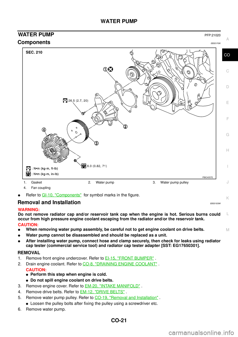
ComponentsEBS01F6K
lRefer toGI-10, "Components"for symbol marks in the figure.
Removal and InstallationEBS01E6W
WARNING:
Do not remove radiator cap and/or reservoir tank cap when the engine is hot. Serious burns could
occur from high pressure engine coolant escaping from the radiator and/or the reservoir tank.
CAUTION:
lWhen removing water pump assembly, be careful not to get engine coolant on drive belts.
lWater pump cannot be disassembled and should be replaced as a unit.
lAfter installing water pump, connect hose and clamp securely, then check for leaks using radiator
cap tester (commercial service tool) and radiator cap tester adapter [SST: EG17650301].
REMOVAL
1. Remove front engine undercover. Refer toEI-15, "FRONT BUMPER".
2. Drain engine coolant. Refer toCO-8, "
DRAINING ENGINE COOLANT".
CAUTION:
lPerform this step when engine is cold.
lDo not spill engine coolant on drive belts.
3. Remove engine cover. Refer toEM-20, "
INTAKE MANIFOLD".
4. Remove drive belts. Refer toEM-12, "
DRIVE BELTS".
5. Remove water pump pulley. Refer toCO-19, "
Removal and Installation".
lLoosen the pulley bolts after fixing the pulley using a screwdriver etc.
6. Remove water pump.
1. Gasket 2. Water pump 3. Water pump pulley
4. Fan coupling
PBIC4057E
Page 908 of 3171
CO-24
THERMOSTAT AND WATER PIPING
Removal and Installation
EBS01E6X
WARNING:
Do not remove radiator cap and/or reservoir tank cap when engine is hot. Serious burns could occur
from high pressure engine coolant escaping from radiator and/or reservoir tank.
REMOVAL
1. Remove front engine undercover and middle engine undercover. Refer toEI-15, "FRONT BUMPER".
2. Drain engine coolant from radiator drain plug at the bottom of radiator, and from water drain plug at the
side of cylinder block. Refer toCO-7, "
Changing Engine Coolant"andEM-110, "CYLINDER BLOCK".
CAUTION:
Perform this step when engine is cold.
3. Remove engine cover. Refer toEM-20, "
INTAKE MANIFOLD".
4. Disconnect radiator hoses (upper and lower) from engine side. Refer toCO-11, "
RADIATOR".
5. Remove air inlet pipe and air duct between air cleaner case and turbocharger. Refer toEM-15, "
AIR
CLEANER AND AIR DUCT"andEM-28, "TURBO CHARGER".
6. Remove water outlet, water inlet and thermostat.
7. Remove thermostat housing.
8. Disconnect heater return hose and water hoses at heater return pipe side, and remove heater return pipe.
9. Remove oil level gauge guide mounting bolt, vacuum hoses (to turbocharger boost control solenoid valve)
and spill hose. Refer toEM-36, "
OIL PAN AND OIL STRAINER",EM-20, "INTAKE MANIFOLD"andEM-
44, "INJECTION TUBE AND FUEL INJECTOR".
10. Disconnect water hoses (to EGR cooler) (A/T models), vacuum hoses and heater feed hose at heater
feed pipe side, and remove heater feed pipe. Refer toEM-20, "
INTAKE MANIFOLD".
INSPECTION AFTER REMOVAL
Thermostat
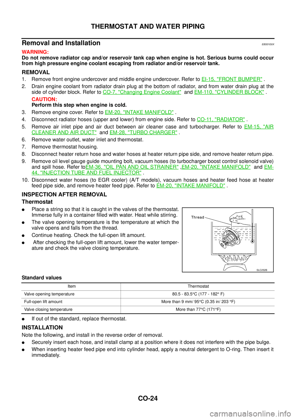
lPlace a string so that it is caught in the valves of the thermostat.
Immerse fully in a container filled with water. Heat while stirring.
lThe valve opening temperature is the temperature at which the
valve opens and falls from the thread.
lContinue heating. Check the full-open lift amount.
lAfter checking the full-open lift amount, lower the water temper-
ature and check the valve closing temperature.
Standard values
lIf out of the standard, replace thermostat.
INSTALLATION
Note the following, and install in the reverse order of removal.
lSecurely insert each hose, and install clamp at a position where it does not interfere with the pipe bulge.
lWhen inserting heater feed pipe end into cylinder head, apply a neutral detergent to O-ring. Then insert it
immediately.
SLC252B
Item Thermostat
Valve opening temperature 80.5 - 83.5°C (177 - 182°F)
Full-open lift amount More than 9 mm/ 95°C (0.35 in/ 203°F)
Valve closing temperature More than 77°C(171°F)
Page 910 of 3171

CO-26
SERVICE DATA AND SPECIFICATIONS (SDS)
SERVICE DATA AND SPECIFICATIONS (SDS)
PFP:00030
Standard and LimitEBS01E6Y
ENGINE COOLANT CAPACITY
Unit: (lmp qt)
THERMOSTAT
RESERVOIR TANK
Unit:kPa(bar,kg/cm2, psi)
Engine coolant capacity
(With reservoir tank at “MAX” level)LHD models Approx. 9.9 (8-3/4)
RHD models Approx. 10.2 (9)
Reservoir tank (at “MAX” level)0.8 (3/4)
Valve opening temperature 80.5 - 83.5°C (177 - 182°F)
Full open lift amount More than 9 mm/ 95°C (0.35 in/203°F)
Valve closing temperature More than 77°C(171°F)
Cap relief pressureStandard 98.2 - 117.8 (0.98 - 1.18, 1.0 - 1.2, 14 - 17)
Limit 59 (0.59, 0.6, 9)
Leakage test pressure 157 (1.57, 1.6, 23)
Page 1032 of 3171
EC-52
TROUBLE DIAGNOSIS
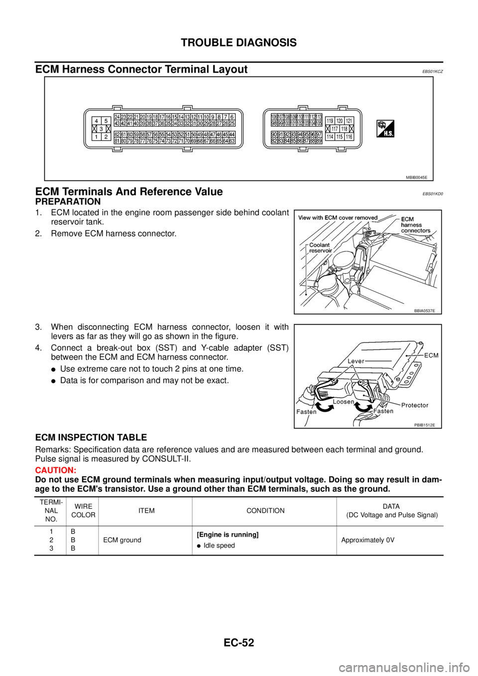
ECM Harness Connector Terminal Layout
EBS01KCZ
ECM Terminals And Reference ValueEBS01KD0
PREPARATION
1. ECM located in the engine room passenger side behind coolant
reservoir tank.
2. Remove ECM harness connector.
3. When disconnecting ECM harness connector, loosen it with
levers as far as they will go as shown in the figure.
4. Connect a break-out box (SST) and Y-cable adapter (SST)
between the ECM and ECM harness connector.
lUse extreme care not to touch 2 pins at one time.
lData is for comparison and may not be exact.
ECM INSPECTION TABLE
Remarks: Specification data are reference values and are measured between each terminal and ground.
Pulse signal is measured by CONSULT-II.
CAUTION:
Do not use ECM ground terminals when measuring input/output voltage. Doing so may result in dam-
age to the ECM's transistor. Use a ground other than ECM terminals, such as the ground.
MBIB0045E
BBIA0537E
PBIB1512E
TERMI-
NAL
NO.WIRE
COLORITEM CONDITIONDATA
(DC Voltage and Pulse Signal)
1
2
3B
B
BECM ground[Engine is running]
lIdle speedApproximately 0V
Page 1113 of 3171
DTC P0217 ENGINE OVER TEMPERATURE
EC-133
C
D
E
F
G
H
I
J
K
L
MA
EC
CONSULT-II Reference Value in Data Monitor ModeEBS01KFL
Specification data are reference values.
On Board Diagnosis LogicEBS01KFM
If the cooling fan or another component in the cooling system malfunctions, engine coolant temperature will
rise.
When the engine coolant temperature reaches an abnormally high temperature condition, a malfunction is
indicated.
CAUTION:
When a malfunction is indicated, be sure to replace the coolant. Refer toCO-7, "
Changing Engine
Coolant". Also, replace the engine oil. Refer toLU-6, "Changing Engine Oil".
1. Fill radiator with coolant up to specified level with a filling speed of 2 liters per minute. Be sure to
use coolant with the proper mixture ratio. Refer toMA-16, "
Engine Coolant Mixture Ratio".
2. After refilling coolant, run engine to ensure that no water-flow noise is emitted.
Overall Function CheckEBS01KFN
Use this procedure to check the overall function of the cooling fan. During this check, a DTC might not be con-
firmed.
WARNING:
lNever remove a radiator cap and/or a reservoir tank cap when the engine is hot. Serious burns
could be caused by high pressure fluid escaping from the radiator and the reservoir tank.
lWrap a thick cloth around cap. Carefully remove the cap by turning it a quarter turn to allow built-
up pressure to escape. Then turn the cap all the way off.
MONITOR ITEM CONDITION SPECIFICATION
COOLING FAN
lEngine: After warming up, idle
the engine
lAir conditioner switch: OFFEngine coolant temperature: 97°C
(207°F) or lessOFF
Engine coolant temperature: Between
98°C (208°F) and 104°C(219°F)LOW
Engine coolant temperature: 105°C
(221°F) or moreHI
DTC No. Trouble diagnosis name DTC detecting condition Possible cause
P0217
0217Engine over temperature
(Overheat)
lCooling fan does not operate properly (Over-
heat).
lCooling fan system does not operate properly
(Overheat).
lEngine coolant was not added to the system
using the proper filling method.
lEngine coolant is not within the specified
range.
lHarness or connectors
(The cooling fan circuit is open or
shorted.)
lIPDM E/R
lCooling fan
lCooling fan (Crankshaft driven)
lRadiator hose
lRadiator
lRadiator cap
lReservoir tank
lReservoir tank cap
lWater pump
lThermostat
For more information, refer toEC-140,
"Main 12 Causes of Overheating".
Page 1114 of 3171
EC-134
DTC P0217 ENGINE OVER TEMPERATURE
WITH CONSULT-II
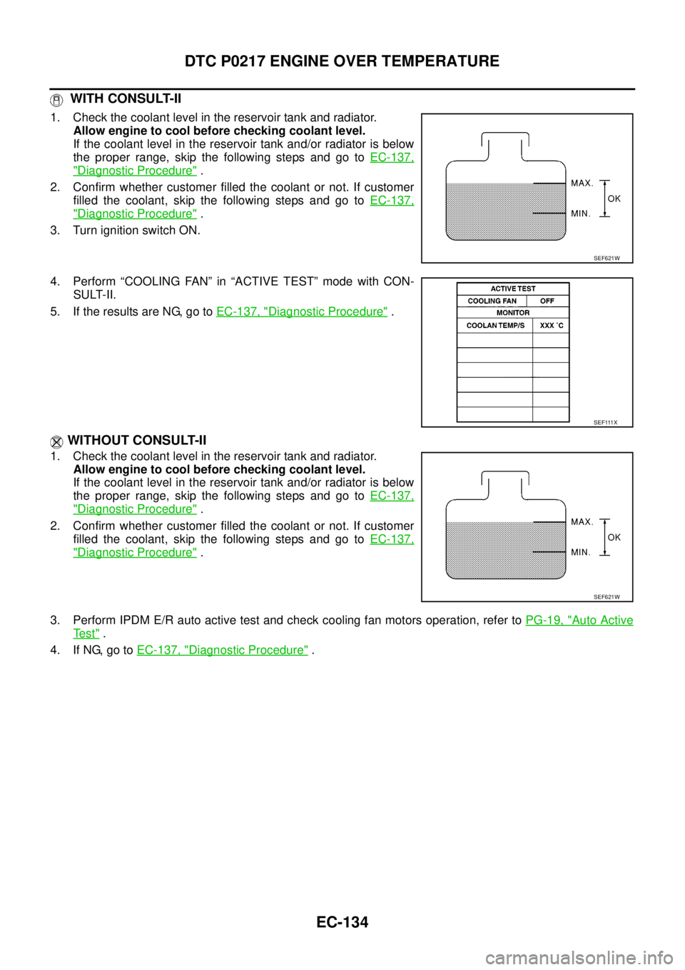
1. Check the coolant level in the reservoir tank and radiator.
Allow engine to cool before checking coolant level.
If the coolant level in the reservoir tank and/or radiator is below
the proper range, skip the following steps and go toEC-137,
"Diagnostic Procedure".
2. Confirm whether customer filled the coolant or not. If customer
filled the coolant, skip the following steps and go toEC-137,
"Diagnostic Procedure".
3. Turn ignition switch ON.
4. Perform “COOLING FAN” in “ACTIVE TEST” mode with CON-
SULT-II.
5. If the results are NG, go toEC-137, "
Diagnostic Procedure".
WITHOUT CONSULT-II
1. Check the coolant level in the reservoir tank and radiator.
Allow engine to cool before checking coolant level.
If the coolant level in the reservoir tank and/or radiator is below
the proper range, skip the following steps and go toEC-137,
"Diagnostic Procedure".
2. Confirm whether customer filled the coolant or not. If customer
filled the coolant, skip the following steps and go toEC-137,
"Diagnostic Procedure".
3. Perform IPDM E/R auto active test and check cooling fan motors operation, refer toPG-19, "
Auto Active
Te s t".
4. If NG, go toEC-137, "
Diagnostic Procedure".
SEF621W
SEF111X
SEF621W
Page 1118 of 3171
EC-138
DTC P0217 ENGINE OVER TEMPERATURE
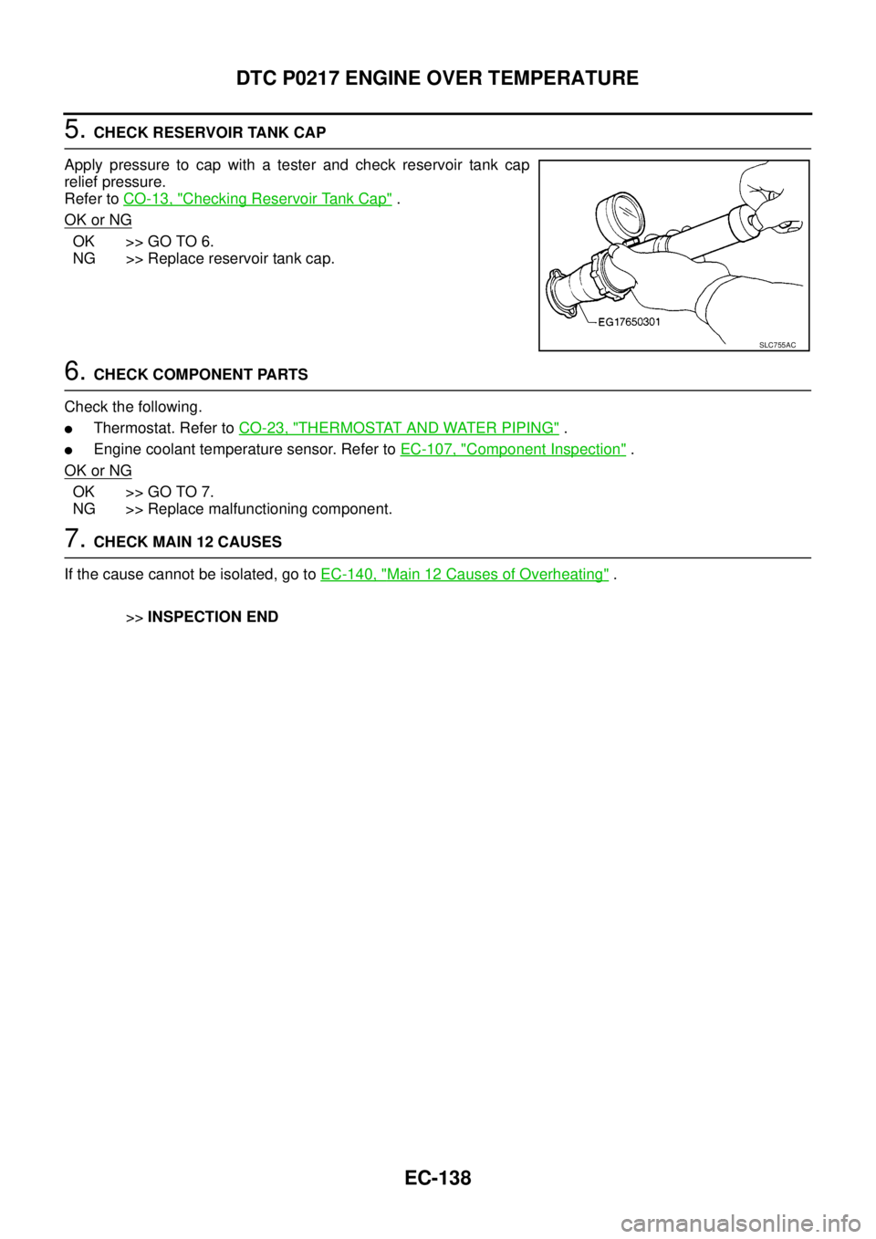
5.CHECK RESERVOIR TANK CAP
Apply pressure to cap with a tester and check reservoir tank cap
relief pressure.
Refer toCO-13, "
Checking Reservoir Tank Cap".
OK or NG
OK >> GO TO 6.
NG >> Replace reservoir tank cap.
6.CHECK COMPONENT PARTS
Check the following.
lThermostat. Refer toCO-23, "THERMOSTAT AND WATER PIPING".
lEngine coolant temperature sensor. Refer toEC-107, "Component Inspection".
OK or NG
OK >> GO TO 7.
NG >> Replace malfunctioning component.
7.CHECK MAIN 12 CAUSES
If the cause cannot be isolated, go toEC-140, "
Main 12 Causes of Overheating".
>>INSPECTION END
SLC755AC
Page 1120 of 3171
EC-140
DTC P0217 ENGINE OVER TEMPERATURE
5.CHECK COOLING FAN MOTOR
Refer toEC-141, "
Component Inspection".
OK or NG
OK >> GO TO 6.
NG >> Replace cooling fan motors.
6.CHECK INTERMITTENT INCIDENT
PerformEC-70, "
TROUBLE DIAGNOSIS FOR INTERMITTENT INCIDENT".
OK or NG
OK >> Replace IPDM E/R. Refer toPG-14, "IPDM E/R (INTELLIGENT POWER DISTRIBUTION MOD-
ULE ENGINE ROOM)".
NG >> Repair or replace harness or connector.
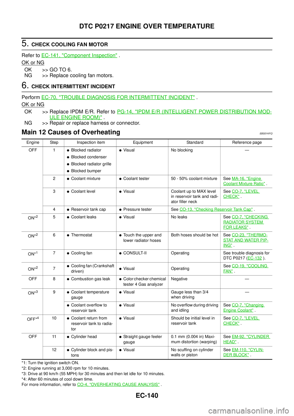
Main 12 Causes of OverheatingEBS01KFQ
*1: Turn the ignition switch ON.
*2: Engine running at 3,000 rpm for 10 minutes.
*3: Drive at 90 km/h (55 MPH) for 30 minutes and then let idle for 10 minutes.
*4: After 60 minutes of cool down time.
For more information, refer toCO-4, "
OVERHEATING CAUSE ANALYSIS". Engine Step Inspection item Equipment Standard Reference page
OFF 1
lBlocked radiator
lBlocked condenser
lBlocked radiator grille
lBlocked bumper
lVisual No blocking —
2
lCoolant mixturelCoolant tester 50 - 50% coolant mixture SeeMA-16, "Engine
Coolant Mixture Ratio".
3
lCoolant levellVisual Coolant up to MAX level
in reservoir tank and radi-
ator filler neckSeeCO-7, "LEVEL
CHECK".
4
lReservoir tank caplPressure tester SeeCO-13, "Checking Reservoir Tank Cap".
ON*
25lCoolant leakslVisual No leaks SeeCO-7, "CHECKING
RADIATOR SYSTEM
FOR LEAKS".
ON*
26lThermostatlTouch the upper and
lower radiator hosesBoth hoses should be hot SeeCO-23, "THERMO-
STAT AND WATER PIP-
ING".
ON*
17lCooling fanlCONSULT-II Operating See trouble diagnosis for
DTC P0217 (EC-132
).
ON*
27lCooling fan (Crankshaft
driven)lVisual OperatingSeeCO-19, "COOLING
FA N".
OFF 8
lCombustion gas leaklColor checker chemical
tester 4 Gas analyzerNegative —
ON*
39lCoolant temperature
gaugelVisual Gauge less than 3/4
when driving—
lCoolant overflow to
reservoir tanklVisual No overflow during driving
and idlingSeeCO-7, "Changing
Engine Coolant".
OFF*
410lCoolant return from
reservoir tank to radia-
torlVisual Should be initial level in
reservoir tankSeeCO-7, "LEVEL
CHECK".
OFF 11
lCylinder headlStraight gauge feeler
gauge0.1 mm (0.004 in) Maxi-
mum distortion (warping)SeeEM-92, "CYLINDER
HEAD".
12
lCylinder block and pis-
tonslVisual No scuffing on cylinder
walls or pistonSeeEM-110, "CYLIN-
DER BLOCK".
Page 2276 of 3171
MA-1
MAINTENANCE
L MAINTENANCE
CONTENTS
C
D
E
F
G
H
I
J
K
M
SECTIONMA
A
B
MA
MAINTENANCE
PRECAUTIONS .......................................................... 3
Precautions for Supplemental Restraint System
(SRS)“AIRBAG”and“SEATBELTPRE-TEN-
SIONER” .................................................................. 3
PREPARATION ........................................................... 4
Special Service Tools ............................................... 4
Commercial Service Tools ........................................ 4
DESCRIPTION ............................................................ 5
Pre-Delivery Inspection Items .................................. 5
GENERAL MAINTENANCE ....................................... 7
General Maintenance ............................................... 7
PERIODIC MAINTENANCE ....................................... 8
Periodic Maintenance ............................................... 8
ENGINE AND EMISSION CONTROL MAINTE-
NANCE (YD25DDTI DIESEL ENGINE) ................ 8
CHASSIS AND BODY MAINTENANCE
(YD25DDTI DIESEL ENGINE) .............................. 9
MAINTENANCE UNDER SEVERE DRIVING
CONDITIONS ...................................................... 10
ENGINE AND EMISSION CONTROL MAINTE-
NANCE (YD25DDTI DIESEL ENGINE) ............... 11
CHASSIS AND BODY MAINTENANCE
(YD25DDTI DIESEL ENGINE) ............................. 11
MAINTENANCE UNDER SEVERE DRIVING
CONDITIONS ...................................................... 13
RECOMMENDED FLUIDS AND LUBRICANTS ...... 14
Fluids and Lubricants ............................................. 14
SAE Viscosity Number ........................................... 15
DIESEL ENGINE ................................................. 15
GEAR OIL ........................................................... 15
Engine Coolant Mixture Ratio ................................ 16
ENGINE MAINTENANCE ......................................... 17
Checking Drive Belts .............................................. 17
Deflection Adjustment ............................................ 18
POWER STEERING OIL PUMP BELT ............... 18
A/C COMPRESSOR, ALTERNATOR AND
WATER PUMP BELT .......................................... 19
Changing Engine Coolant ...................................... 19
DRAINING ENGINE COOLANT ......................... 19
REFILLING ENGINE COOLANT ........................ 20FLUSHING COOLING SYSTEM ......................... 21
Checking Cooling System ...................................... 21
CHECKING COOLING SYSTEM HOSES ........... 21
CHECKING RADIATOR ...................................... 21
CHECKING RESERVOIR TANK CAP ................. 21
CHECKING RADIATOR SYSTEM FOR LEAKS... 22
Checking Fuel Lines ............................................... 23
Changing Fuel Filter ............................................... 23
REMOVAL ........................................................... 23
INSTALLATION ................................................... 24
INSPECTION AFTER INSTALLATION ................ 24
Draining Water from Fuel Filter .............................. 25
Changing Engine Air Cleaner Filter ........................ 25
DRY PAPER TYPE .............................................. 25
Changing Engine Oil ............................................... 25
Changing Oil Filter .................................................. 26
REMOVAL ........................................................... 26
INSTALLATION ................................................... 26
INSPECTION AFTER INSTALLATION ................ 27
CHASSIS AND BODY MAINTENANCE ................... 28
Checking the Exhaust System ................................ 28
Checking Clutch Fluid Level and Leaks ................. 28
Checking Clutch System ........................................ 28
Checking M/T Oil .................................................... 28
Changing M/T Oil .................................................... 29
Checking A/T Fluid ................................................. 29
Changing A/T Fluid ................................................. 31
Checking Transfer Fluid ......................................... 31
FLUID LEAKAGE AND FLUID LEVEL ................ 31
Changing Transfer Fluid ......................................... 32
DRAINING ........................................................... 32
FILLING ............................................................... 32
Checking Propeller Shaft ........................................ 32
Checking Front Final Drive Oil (Front Differential
Gear Oil) ................................................................. 32
OIL LEAKAGE AND OIL LEVEL ......................... 32
Changing Front Final Drive Oil (Front Differential
Gear Oil) ................................................................. 33
DRAINING ........................................................... 33
FILLING ............................................................... 33
Page 2277 of 3171

MA-2
Checking Rear Final Drive Oil (Rear Differential
Gear Oil) ................................................................. 33
OIL LEAKAGE AND OIL LEVEL ......................... 33
Changing Rear Final Drive Oil (Rear Differential
Gear Oil) ................................................................. 34
DRAINING ........................................................... 34
FILLING ............................................................... 34
Balancing Wheels ................................................... 34
Tire Rotation ........................................................... 34
Checking Brake Fluid Level and Leaks .................. 35
Checking Brake Lines and Cables ......................... 35
Changing Brake Fluid ............................................. 35
Checking Disc Brake .............................................. 35
ROTOR ................................................................ 35
CALIPER ............................................................. 36
PAD ..................................................................... 36
Checking Drum Brake ............................................ 36
DRUM .................................................................. 36
WHEEL CYLINDER ............................................. 36
LINING ................................................................. 37
Checking Steering Gear and Linkage ..................... 37
STEERING GEAR ............................................... 37
STEERING LINKAGE .......................................... 37
Checking Power Steering Fluid and Lines .............. 37CHECKING FLUID LEVEL .................................. 37
CHECKING LINES ............................................... 37
Checking Axle and Suspension Parts ..................... 38
FRONT AND REAR AXLE AND SUSPENSION
PARTS ................................................................. 38
FRONT DRIVE SHAFT ........................................ 38
Lubricating Locks, Hinges and Hood Latches ......... 39
Checking Seat Belts, Buckles, Retractors, Anchors
and Adjusters .......................................................... 40
Checking Body Corrosion ....................................... 40
HEMMED PANELS .............................................. 40
PANEL JOINT ...................................................... 40
PANEL EDGE ...................................................... 40
PARTS CONTACT ............................................... 40
PROTECTORS .................................................... 40
ANTI-CORROSION MATERIALS ........................ 40
DRAIN HOLES ..................................................... 40
SERVICE DATA AND SPECIFICATIONS (SDS) ...... 41
Standard and Limit .................................................. 41
BELT DEFLECTION ............................................ 41
RESERVOIR TANK ............................................. 41
ENGINE COOLANT CAPACITY (APPROXI-
MATE) .................................................................. 41
ENGINE OIL CAPACITY (APPROXIMATE) ........ 41