fuse box NISSAN NAVARA 2005 Repair User Guide
[x] Cancel search | Manufacturer: NISSAN, Model Year: 2005, Model line: NAVARA, Model: NISSAN NAVARA 2005Pages: 3171, PDF Size: 49.59 MB
Page 674 of 3171
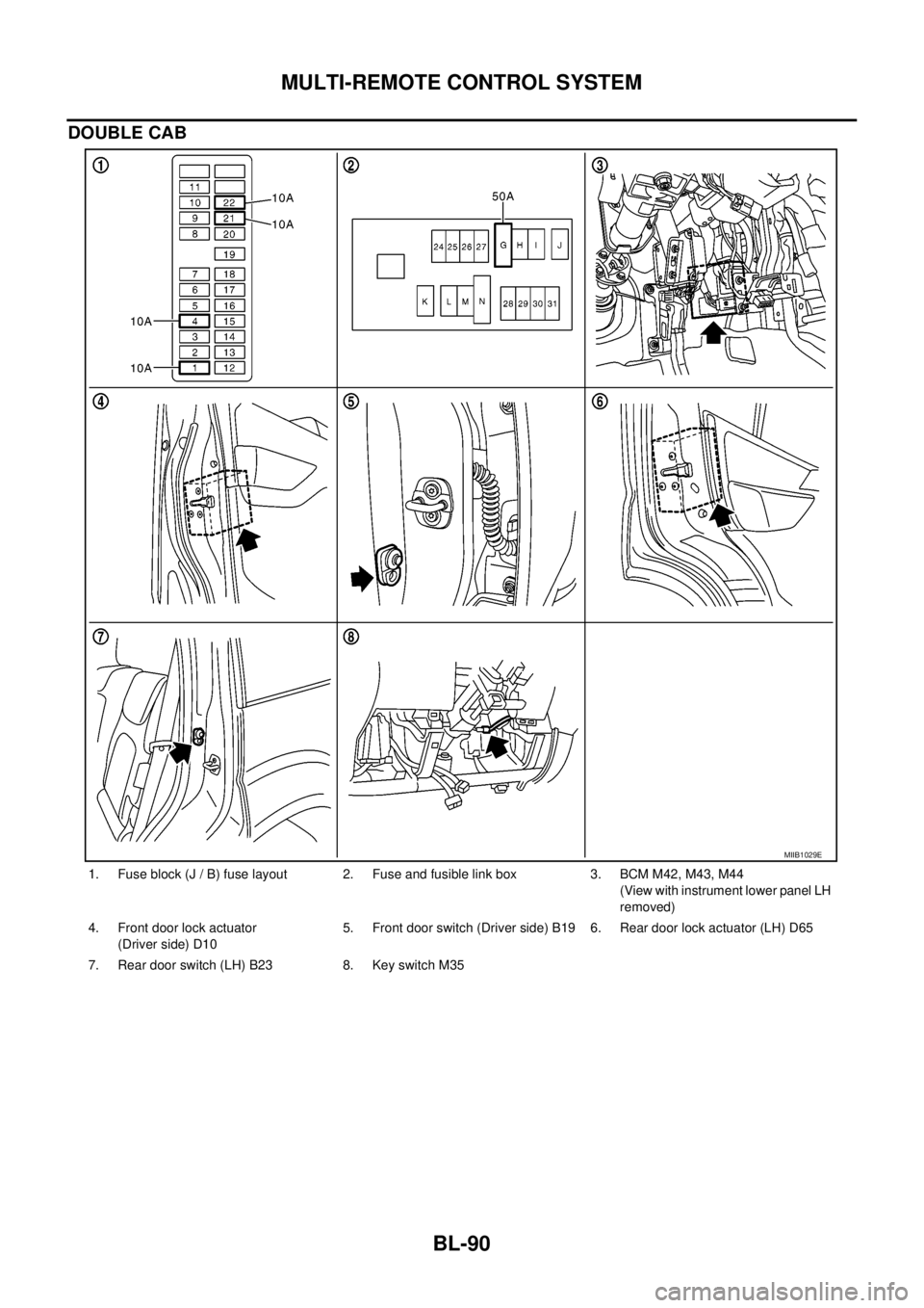
BL-90
MULTI-REMOTE CONTROL SYSTEM
DOUBLE CAB
1. Fuse block (J / B) fuse layout 2. Fuse and fusible link box 3. BCM M42, M43, M44
(View with instrument lower panel LH
removed)
4. Front door lock actuator
(Driver side) D105. Front door switch (Driver side) B19 6. Rear door lock actuator (LH) D65
7. Rear door switch (LH) B23 8. Key switch M35
MIIB1029E
Page 675 of 3171

MULTI-REMOTE CONTROL SYSTEM
BL-91
C
D
E
F
G
H
J
K
L
MA
B
BL
System DescriptionEIS00DBE
INPUTS
Power is supplied at all times
lto BCM terminal 57
lthrough 50A fusible link (letterG, located in the fuse and fusible link box).
lto BCM terminal 41
lthrough 10A fuse [No. 21, located in the fuse block (J/B)].
When the key switch is ON (key is inserted in ignition key cylinder), power is supplied
lto BCM terminal 5
lthrough key switch terminals 2 and 1
lthrough 10A fuse [No. 22, located in the fuse block (J/B)].
When the ignition switch is ACC or ON, power is supplied
lto BCM terminal 4
lthrough 10A fuse [No. 4, located in the fuse block (J/B)].
When the ignition switch is ON or START, power is supplied
lto BCM terminal 3
lthrough 10A fuse [No. 1, located in the fuse block (J/B)].
When the front door switch (driver side) is ON (door is OPEN), ground is supplied
lto BCM terminal 15
lthrough front door switch (driver side) terminal 2
lto front door switch (driver side) case ground.
When the front door switch (passenger side) is ON (door is OPEN), ground is supplied
lto BCM terminal 14
lthrough front door switch (passenger side) terminal 2
lto front door switch (passenger side) case ground.
When the rear door switch LH is ON (door is OPEN), ground is supplied
lto BCM terminal 16
lthrough rear door switch LH terminal 2
lto rear door switch LH case ground.
When the rear door switch RH is ON (door is OPEN), ground is supplied
lto BCM terminal 12
lthrough rear door switch RH terminal 2
lto rear door switch RH case ground.
The multi-remote control system controls operation of the
lpowerdoorlock
linterior lamp and ignition keyhole illumination
lhazard reminder
lauto door lock operation
OPERATING PROCEDURE
Power Door Lock Operation
BCM receives a LOCK signal from keyfob. BCM locks all doors with input of LOCK signal from keyfob.
When an UNLOCK signal is sent from keyfob once, driver's door is unlocked.
Then, if an UNLOCK signal is sent from keyfob again within 5 seconds, all doors are unlocked.
Hazard Reminder
When the doors are locked or unlocked by keyfob, power is supplied to hazard warning lamp.
Hazard reminder does not operate if any door switches are ON (any doors are OPEN).
How to change hazard and horn reminder mode
Hazard and horn reminder can be changed using “WORK SUPPORT” mode in “MULTI ANSWER BACK SET”.
Refer toBL-102, "
CONSULT-II Function (BCM)".
Page 722 of 3171
BL-138
THEFT WARNING SYSTEM
THEFT WARNING SYSTEM
PFP:28590
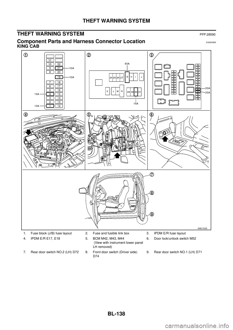
Component Parts and Harness Connector LocationEIS00DBW
KING CAB
1. Fuse block (J/B) fuse layout 2. Fuse and fusible link box 3. IPDM E/R fuse layout
4. IPDM E/R E17, E18 5. BCM M42, M43, M44
(View with instrument lower panel
LH removed)6. Door lock/unlock switch M52
7. Rear door switch NO.2 (LH) D72 8. Front door switch (Driver side)
D749. Rear door switch NO.1 (LH) D71
MIIB1033E
Page 723 of 3171
THEFT WARNING SYSTEM
BL-139
C
D
E
F
G
H
J
K
L
MA
B
BL
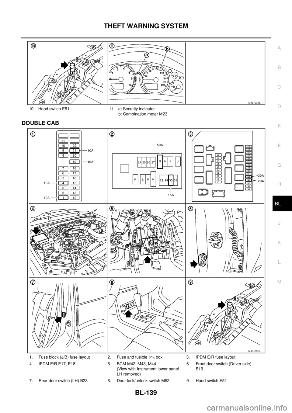
DOUBLE CAB
10. Hood switch E51 11. a: Security indicator
b: Combination meter M23
MIIB1034E
1. Fuse block (J/B) fuse layout 2. Fuse and fusible link box 3. IPDM E/R fuse layout
4. IPDM E/R E17, E18 5. BCM M42, M43, M44
(View with Instrument lower panel
LH removed)6. Front door switch (Driver side)
B19
7. Rear door switch (LH) B23 8. Door lock/unlock switch M52 9. Hood switch E51
MIIB1031E
Page 725 of 3171

THEFT WARNING SYSTEM
BL-141
C
D
E
F
G
H
J
K
L
MA
B
BL
2. A door is unlocked without using the keyfob.
3. Disconnect and connecting the battery connector before canceling armed phase.
POWER SUPPLY AND GROUND CIRCUIT
Power is supplied at all times
lthrough 10A fuse [No.19, located in the fuse block (J/B)]
lto combination meter (security indicator lamp) terminal 3
lthrough 50A fusible link (letterG, located in the fuse and fusible link box)
lto BCM terminal 57
lthrough 10A fuse [No. 21, located in the fuse block (J/B)]
lto BCM terminal 41
lthrough 15A fuse (No. 30, located in the fuse and fusible link box)
lto horn relay terminal 2
lthrough 20A fuse (No. 52, located in the IPDM E/R)
lthrough 20A fuse (No. 53, located in the IPDM E/R),
lto IPDM E/R internal CPU.
With the ignition switch in the ACC or ON position, power is supplied
lthrough 10A fuse [No. 4, located in the fuse block (J/B)]
lto BCM terminal 4.
Ground is supplied
lto BCM terminal 55
lthrough body grounds M21, M80 and M83
lto IPDM E/R terminals 38 and 59
lthrough body ground E21, E41 and E61.
INITIAL CONDITION TO ACTIVATE THE SYSTEM
The operation of the theft warning system is controlled by the engine hood and doors.
To activate the theft warning system, BCM must receive signals indicating the doors are closed and locked.
When a door is open, BCM terminal 12, 14, 15 or 16 receives a ground signal from each door switch.
When the engine hood is open, IPDM E/R terminal 41 receives a ground signal
THEFT WARNING SYSTEM ALARM OPERATION
The vehicle security system is triggered by
lopening a door
lopening the hood
ldetecting battery disconnect/connection.
The vehicle security system will be triggered once the system is in armed phase,
when BCM receives a ground signal at terminals 12, 14, 15, 16 (door switch) or IPDM E/R receives a ground
signal at terminal 41 (hood switch).
When the vehicle security system is triggered, siren control unit or horn is activate.
The alarm automatically turns off after 30 seconds, but will reactivate if the vehicle is tampered with again.
THEFT WARNING SYSTEM DEACTIVATION
To deactivate the theft warning system, a door must be unlocked with keyfob.
When the BCM receives either one of these signals or unlock signal from keyfob the theft warning system is
deactivated. (Disarmed phase)
CAN Communication System DescriptionEIS00DBY
Refer toLAN-23, "CAN COMMUNICATION".
Page 754 of 3171
BL-170
NATS(NISSAN ANTI-THEFT SYSTEM)
NATS(NISSAN ANTI-THEFT SYSTEM)
PFP:28591
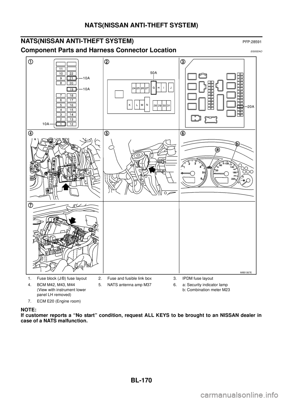
Component Parts and Harness Connector LocationEIS00DAO
NOTE:
If customer reports a “No start” condition, request ALL KEYS to be brought to an NISSAN dealer in
case of a NATS malfunction.
1. Fuse block (J/B) fuse layout 2. Fuse and fusible link box 3. IPDM fuse layout
4. BCM M42, M43, M44
(View with instrument lower
panel LH removed)5. NATS antenna amp M37 6. a: Security indicator lamp
b: Combination meter M23
7. ECM E20 (Engine room)
MIIB1067E
Page 763 of 3171
NATS(NISSAN ANTI-THEFT SYSTEM)
BL-179
C
D
E
F
G
H
J
K
L
MA
B
BL
Diagnostic Procedure 1EIS00DB1
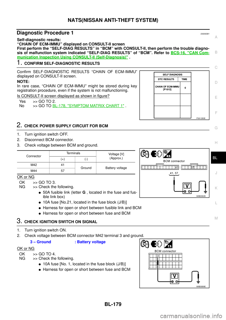
Self-diagnostic results:
“CHAIN OF ECM-IMMU” displayed on CONSULT-II screen
First perform the “SELF-DIAG RESULTS” in “BCM” with CONSULT-II, then perform the trouble diagno-
sis of malfunction system indicated “SELF-DIAG RESULTS” of “BCM”. Refer toBCS-16, "
CAN Com-
munication Inspection Using CONSULT-II (Self-Diagnosis)".
1.CONFIRM SELF-DIAGNOSTIC RESULTS
Confirm SELF-DIAGNOSTIC RESULTS “CHAIN OF ECM-IMMU”
displayed on CONSULT-II screen.
NOTE:
In rare case, “CHAIN OF ECM-IMMU” might be stored during key
registration procedure, even if the system is not malfunctioning.
Is CONSULT-II screen displayed as shown in figure?
Ye s > > G O T O 2 .
No >> GO TOBL-178, "
SYMPTOM MATRIX CHART 1".
2.CHECK POWER SUPPLY CIRCUIT FOR BCM
1. Turn ignition switch OFF.
2. Disconnect BCM connector.
3. Check voltage between BCM and ground.
OK or NG
OK >> GO TO 3.
NG >> Check the following.
l50A fusible link (letterG, located in the fuse and fus-
ible link box)
l10A fuse [No.21, located in the fuse block (J/B)]
lHarness for open or short between fusible link and BCM
lHarness for open or short between fuse and BCM
3.CHECK IGNITION SWITCH ON SIGNAL
1. Turn ignition switch ON.
2. Check voltage between BCM connector M42 terminal 3 and ground.
OK or NG
OK >> GO TO 4.
NG >> Check the following.
l10A fuse [No. 1, located in the fuse block (J/B)]
lHarness for open or short between fuse and BCM
PIIA1260E
ConnectorTerminals
Voltag e [V]
(Approx.)
(+) (-)
M42 41
Ground Battery voltage
M44 57
MIIB0902E
3 – Ground : Battery voltage
MIIB0899E
Page 961 of 3171
WARNING CHIME
DI-51
C
D
E
F
G
H
I
J
L
MA
B
DI
WARNING CHIMEPFP:24814
System DescriptionEKS00L9D
lBuzzer for warning chime system is installed in the combination meter.
lThe buzzer sounds at the following conditions:
–When combination meter receives buzzer output signal with CAN communication line
–When combination meter judges warning chime sound condition is found
POWER SUPPLY AND GROUND CIRCUIT
Power is supplied at all times
lthrough 50A fusible link (letterG, located in the fuse and fusible link box)
lto BCM terminal 57.
With ignition switch in the ON or START position, power is supplied
lthrough 10A fuse [No. 1, located in the fuse block (J/B)]
lto BCM terminal 3.
Ground is supplied
lto BCM terminal 55
lthrough grounds M21, M80 and M83.
LIGHT WARNING CHIME
With ignition switch in OFF or ACC position, driver's door open, and lighting switch in 1ST or 2ND position, the
light warning chime will sound.
lBCM detects ignition switch in OFF or ACC position, front door switch (driver side) ON, and lighting switch
in 1ST or 2ND position. And then transmits buzzer output signal (light warning chime) to combination
meter with CAN communication line.
lWhen combination meter receives buzzer output signal (light warning chime), it sounds the buzzer.
NOTE:
For further details of combination switch, refer toBCS-3, "
COMBINATION SWITCH READING FUNCTION".
KEY REMINDER WARNING CHIME
Key reminder chime sounds, at the same time, when key reminder system starts operating.
key reminder chime also sounds when the following three conditions are simultaneously met.
lKey is inserted in the ignition key cylinder
lDriver¢s door is opened
lThe setting of driver¢s door lock knob is “LOCK”
For information regarding key reminder system, refer toBL-21, "
POWER DOOR LOCK SYSTEM".
LOW-FUEL WARNING CHIME
Low-fuel warning chime sounds, when low-fuel warning lamp is turned ON.
Combination meter sounds warning chime three times when low-fuel warning lamp turns ON.
Page 1474 of 3171
EM-92
CYLINDER HEAD
CYLINDER HEAD
PFP:11041
On-Vehicle ServiceEBS01E6A
CHECKING COMPRESSION PRESSURE
1. Warm up engine thoroughly. Then, stop it.
2. Using CONSULT-II, make sure no error codes are indicated for self-diagnosis items. Refer toEC-38,
"Basic Inspection".
lDo not disconnect CONSULT-II until the end of this operation; it will be used to check engine rpm and
for error detection at the end of this operation.
3. Disconnect the battery cable from the negative terminal.
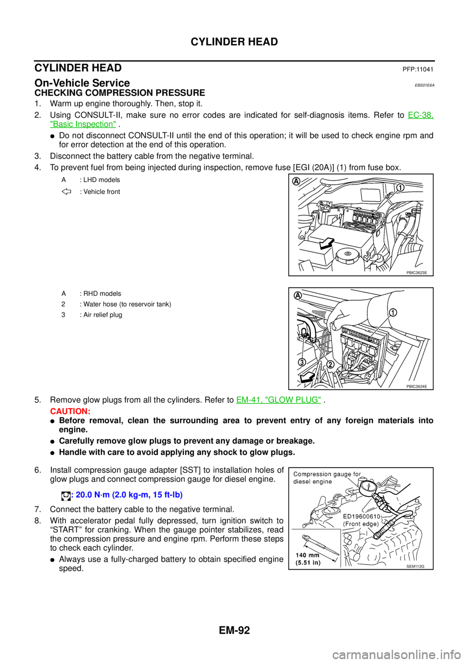
4. To prevent fuel from being injected during inspection, remove fuse [EGI (20A)] (1) from fuse box.
5. Remove glow plugs from all the cylinders. Refer toEM-41, "
GLOW PLUG".
CAUTION:
lBefore removal, clean the surrounding area to prevent entry of any foreign materials into
engine.
lCarefully remove glow plugs to prevent any damage or breakage.
lHandle with care to avoid applying any shock to glow plugs.
6. Install compression gauge adapter [SST] to installation holes of
glow plugs and connect compression gauge for diesel engine.
7. Connect the battery cable to the negative terminal.
8. With accelerator pedal fully depressed, turn ignition switch to
“START” for cranking. When the gauge pointer stabilizes, read
the compression pressure and engine rpm. Perform these steps
to check each cylinder.
lAlways use a fully-charged battery to obtain specified engine
speed.
A : LHD models
: Vehicle front
PBIC3623E
A : RHD models
2 : Water hose (to reservoir tank)
3:Airreliefplug
PBIC3624E
: 20.0 N·m (2.0 kg-m, 15 ft-lb)
SEM112G
Page 1639 of 3171
HOW TO USE THIS MANUAL
GI-17
C
D
E
F
G
H
I
J
K
L
MB
GI
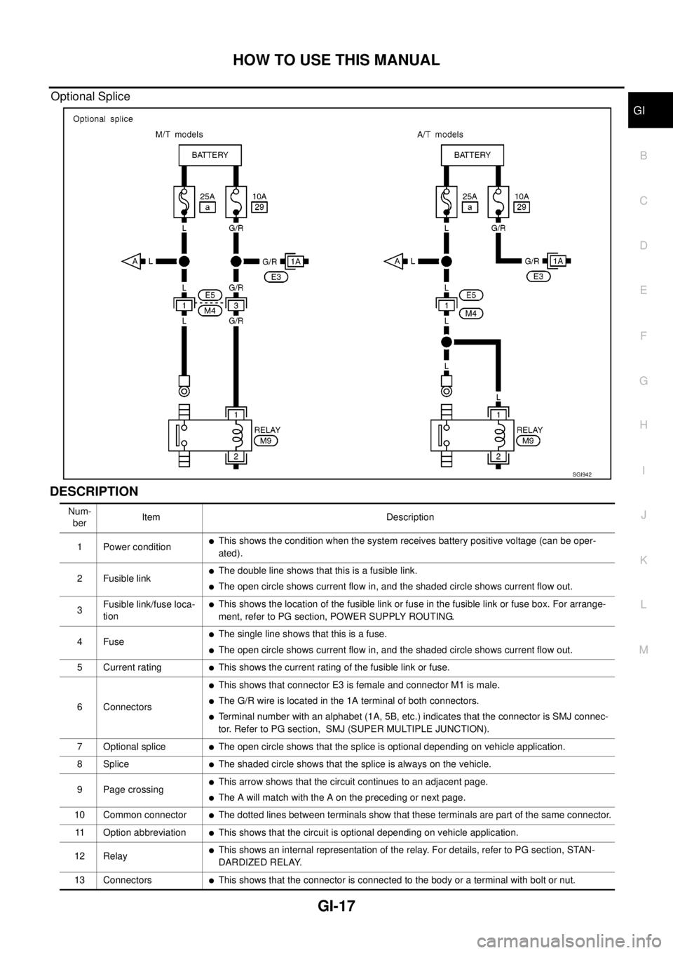
Optional Splice
DESCRIPTION
SGI942
Num-
berItem Description
1 Power condition
lThis shows the condition when the system receives battery positive voltage (can be oper-
ated).
2 Fusible link
lThe double line shows that this is a fusible link.
lThe open circle shows current flow in, and the shaded circle shows current flow out.
3Fusible link/fuse loca-
tion
lThis shows the location of the fusible link or fuse in the fusible link or fuse box. For arrange-
ment, refer to PG section, POWER SUPPLY ROUTING.
4Fuse
lThe single line shows that this is a fuse.
lThe open circle shows current flow in, and the shaded circle shows current flow out.
5 Current rating
lThis shows the current rating of the fusible link or fuse.
6 Connectors
lThis shows that connector E3 is female and connector M1 is male.
lThe G/R wire is located in the 1A terminal of both connectors.
lTerminal number with an alphabet (1A, 5B, etc.) indicates that the connector is SMJ connec-
tor. Refer to PG section, SMJ (SUPER MULTIPLE JUNCTION).
7 Optional splice
lThe open circle shows that the splice is optional depending on vehicle application.
8Splice
lThe shaded circle shows that the splice is always on the vehicle.
9 Page crossing
lThis arrow shows that the circuit continues to an adjacent page.
lThe A will match with the A on the preceding or next page.
10 Common connector
lThe dotted lines between terminals show that these terminals are part of the same connector.
11 Option abbreviation
lThis shows that the circuit is optional depending on vehicle application.
12 Relay
lThis shows an internal representation of the relay. For details, refer to PG section, STAN-
DARDIZED RELAY.
13 Connectors
lThis shows that the connector is connected to the body or a terminal with bolt or nut.