oil type NISSAN NAVARA 2005 Repair Owner's Guide
[x] Cancel search | Manufacturer: NISSAN, Model Year: 2005, Model line: NAVARA, Model: NISSAN NAVARA 2005Pages: 3171, PDF Size: 49.59 MB
Page 2403 of 3171
MTC-16
PREPARATION
PREPARATION
PFP:00002
Special Service ToolsEJS0062C
The actual shapes of Kent-Moore tools may differ from those of special service tools illustrated here.
HFC-134a (R-134a) Service Tools and EquipmentEJS0062D
Never mix HFC-134a (R-134a) refrigerant and/or its specified lubricant with CFC-12 (R-12) refrigerant and/or
its lubricant.
Separate and non-interchangeable service equipment must be used for handling each type of refrigerant/lubri-
cant.
Refrigerant container fittings, service hose fittings and service equipment fittings (equipment which handles
refrigerant and/or lubricant) are different between CFC-12 (R-12) and HFC-134a (R-134a). This is to avoid
mixed use of the refrigerants/lubricant.
Adapters that convert one size fitting to another must never be used: refrigerant/lubricant contamination will
occur and compressor malfunction will result.
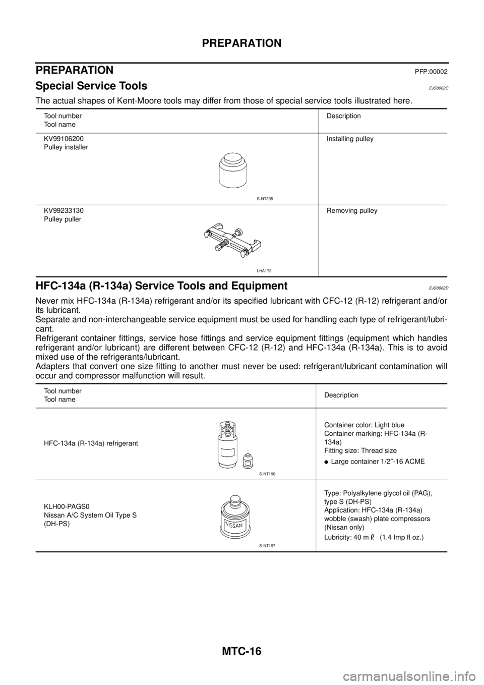
Tool number
Tool nameDescription
KV99106200
Pulley installerInstalling pulley
KV99233130
Pulley pullerRemoving pulley
S-NT235
LHA172
Tool number
Tool nameDescription
HFC-134a (R-134a) refrigerantContainer color: Light blue
Container marking: HFC-134a (R-
134a)
Fitting size: Thread size
lLarge container 1/2²-16 ACME
KLH00-PAGS0
Nissan A/C System Oil Type S
(DH-PS)Type: Polyalkylene glycol oil (PAG),
type S (DH-PS)
Application: HFC-134a (R-134a)
wobble (swash) plate compressors
(Nissan only)
Lubricity: 40 m (1.4 Imp fl oz.)
S-NT196
S-NT197
Page 2633 of 3171
PS-6
POWER STEERING FLUID
POWER STEERING FLUID
PFP:KLF20
Checking Fluid LevelEGS001LD
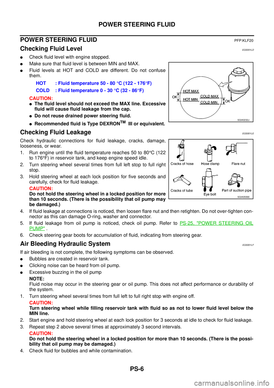
lCheck fluid level with engine stopped.
lMake sure that fluid level is between MIN and MAX.
lFluid levels at HOT and COLD are different. Do not confuse
them.
CAUTION:
lThe fluid level should not exceed the MAX line. Excessive
fluid will cause fluid leakage from the cap.
lDo not reuse drained power steering fluid.
lRecommended fluid is Type DEXRONTMIII or equivalent.
Checking Fluid LeakageEGS001LE
Check hydraulic connections for fluid leakage, cracks, damage,
looseness, or wear.
1. Run engine until the fluid temperature reaches 50 to 80°C(122
to 176°F) in reservoir tank, and keep engine speed idle.
2. Turn steering wheel several times from full left stop to full right
stop.
3. Hold steering wheel at each lock position for five seconds and
carefully, check for fluid leakage.
CAUTION:
Do not hold the steering wheel in a locked position for more
than 10 seconds. (There is the possibility that oil pump may
be damaged.)
4. If fluid leakage at connections is noticed, then loosen flare nut and then retighten. Do not over-tighten con-
nector as this can damage O-ring, washer and connector.
5. If fluid leakage from oil pump is noticed, check oil pump. Refer toPS-25, "
POWER STEERING OIL
PUMP".
6. Check steering gear boots for accumulation of fluid, indicating from steering gear.
Air Bleeding Hydraulic SystemEGS001LF
If air bleeding is not complete, the following symptoms can be observed.
lBubbles are created in reservoir tank.
lClicking noise can be heard from oil pump.
lExcessive buzzing in the oil pump
NOTE:
Fluid noise may occur in the steering gear or oil pump. This does not affect performance or durability of
the system.
1. Turn steering wheel several times from full left to full right stop with engine off.
CAUTION:
Turn steering wheel while filling reservoir tank with fluid so as not to lower fluid level below the
MIN line.
2. Start engine and hold steering wheel at each lock position for 3 seconds at idle to check for fluid leakage.
3. Repeat step 2 above several times at approximately 3 second intervals.
CAUTION:
Do not hold the steering wheel in a locked position for more than 10 seconds. (There is the possi-
bility that oil pump may be damaged.)
4. Check fluid for bubbles and while contamination.HOT : Fluid temperature 50 - 80°C (122 - 176°F)
COLD : Fluid temperature 0 - 30°C(32-86°F)
SGIA0232J
SGIA0506E
Page 2643 of 3171
PS-16
POWER STEERING GEAR AND LINKAGE
Disassembly and Assembly
EGS001LK
COMPONENT
CAUTION:
lDisassemble and assemble steering gear assembly by securing the mounting area in a vise using
copper plates.
lClean steering gear assembly with kerosene before disassembling. Be careful to avoid splashing
or applying any kerosene over connector of discharge port or return port.
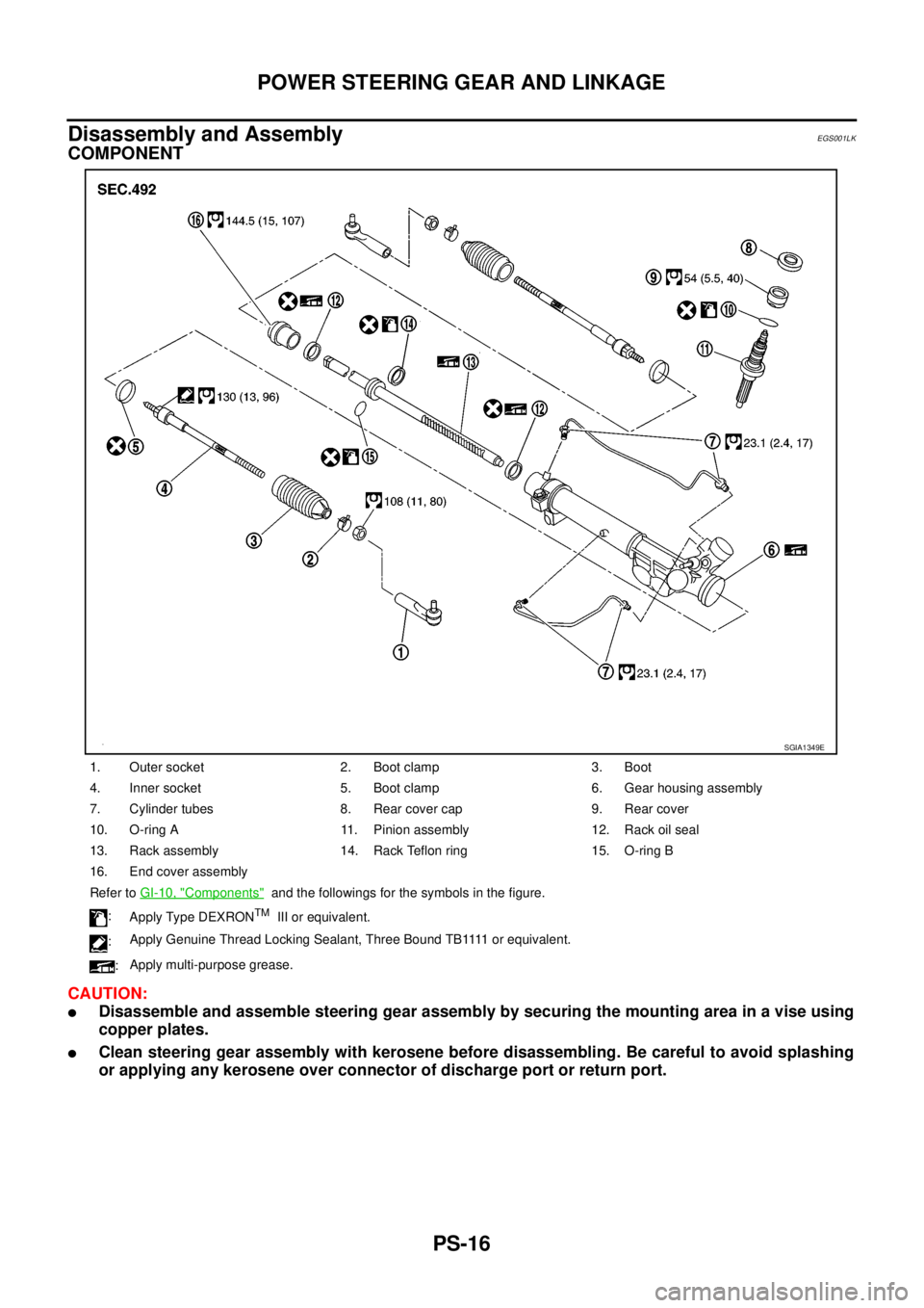
1. Outer socket 2. Boot clamp 3. Boot
4. Inner socket 5. Boot clamp 6. Gear housing assembly
7. Cylinder tubes 8. Rear cover cap 9. Rear cover
10. O-ring A 11. Pinion assembly 12. Rack oil seal
13. Rack assembly 14. Rack Teflon ring 15. O-ring B
16. End cover assembly
Refer toGI-10, "
Components"and the followings for the symbols in the figure.
:
Apply Type DEXRON
TMIII or equivalent.
:A p p l y G e n u i n e T h r e a d L o c k i n g S e a l a n t , T h r e e B o u n d T B 1111 o r e q u i v a l e n t .
:Apply multi-purpose grease.
SGIA1349E
Page 2653 of 3171
PS-26
POWER STEERING OIL PUMP
INSTALLATION
Installation is the reverse order of removal. For tightening torque, refer toPS-30, "HYDRAULIC LINE".
lPerform the following procedure after installing.
–Adjust belt tension. Refer toEM-12, "DRIVE BELTS".
–Bleed air. Refer toPS-6, "Air Bleeding Hydraulic System".
Disassembly and AssemblyEGS001LN
COMPONENT
INSPECTION BEFORE DISASSEMBLY
Disassemble oil pump only when the following malfunctions occur.
lIf oil leakage is found on oil pump.
lOil pump pulley is damaged or deformed.
lPerformance of oil pump is low.
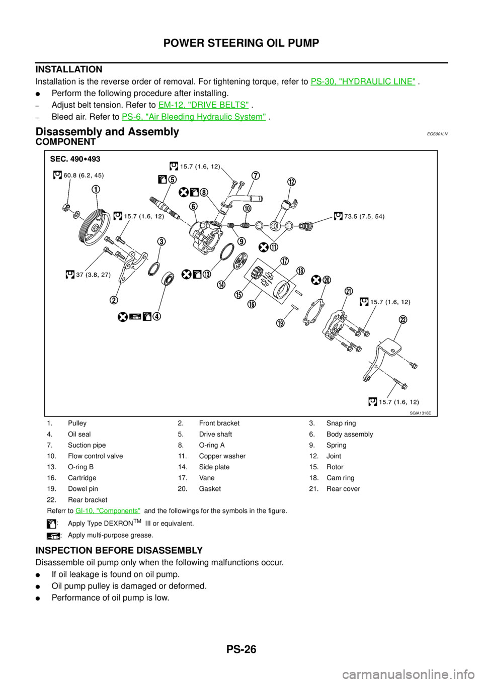
1. Pulley 2. Front bracket 3. Snap ring
4. Oil seal 5. Drive shaft 6. Body assembly
7. Suction pipe 8. O-ring A 9. Spring
10. Flow control valve 11. Copper washer 12. Joint
13. O-ring B 14. Side plate 15. Rotor
16. Cartridge 17. Vane 18. Cam ring
19. Dowel pin 20. Gasket 21. Rear cover
22. Rear bracket
Referr toGI-10, "
Components"and the followings for the symbols in the figure.
:
Apply Type DEXRON
TMIII or equivalent.
:Apply multi-purpose grease.
SGIA1318E
Page 2679 of 3171

RF-2
PRECAUTIONS
PRECAUTIONS
PFP:00001
Precautions for Supplemental Restraint System (SRS) “AIR BAG” and “SEAT
BELT PRE-TENSIONER”
EIS00CE9
The Supplemental Restraint System such as “AIR BAG” and “SEAT BELT PRE-TENSIONER”, used along
with a front seat belt, helps to reduce the risk or severity of injury to the driver and front passenger for certain
types of collision. Information necessary to service the system safely is included in the SRS and SB section of
this Service Manual.
WARNING:
lTo avoid rendering the SRS inoperative, which could increase the risk of personal injury or death
in the event of a collision which would result in air bag inflation, all maintenance must be per-
formed by an authorized NISSAN/INFINITI dealer.
lImproper maintenance, including incorrect removal and installation of the SRS, can lead to per-
sonal injury caused by unintentional activation of the system. For removal of Spiral Cable and Air
Bag Module, see the SRS section.
lDo not use electrical test equipment on any circuit related to the SRS unless instructed to in this
Service Manual. SRS wiring harnesses can be identified by yellow and/or orange harnesses or
harness connectors.
PrecautionsEIS00B92
lDisconnect both battery cables in advance.
lNever tamper with or force air bag lid open, as this may adversely affect air bag performance.
lBe careful not to scratch pad and other parts.
lWhen removing or disassembling any part, be careful not to damage or deform it. Protect parts which may
get in the way with cloth.
lWhen removing parts with a screwdriver or other tool, protect parts by wrapping them with vinyl or tape.
lKeep removed parts protected with cloth.
lIf a clip is deformed or damaged, replace it.
lIf an unreusable part is removed, replace it with a new one.
lTighten bolts and nuts firmly to the specified torque.
lAfter re-assembly has been completed, make sure each part functions correctly.
lRemove stains in the following way.
Water-soluble stains:
Dip a soft cloth in warm water, and then squeeze it tightly. After wiping the stain, wipe with a soft dry cloth.
Oil stain:
Dissolve a synthetic detergent in warm water (density of 2 to 3% or less), dip the cloth, then clean off the stain
with the cloth. Next, dip the cloth in fresh water and squeeze it tightly. Then clean off the detergent completely.
Thenwipetheareawithasoftdrycloth.
lDo not use any organic solvent, such as thinner or benzine.
Page 2719 of 3171
![NISSAN NAVARA 2005 Repair Owners Guide RFD-16
[WITH LIMITED SLIP DIFFERENTIAL]
REAR FINAL DRIVE ASSEMBLY
ASSEMBLY INSPECTION AND ADJUSTMENT
lBefore inspection and adjustment, drain gear oil.
Total Preload Torque
1. Rotate drive pinion back](/img/5/57362/w960_57362-2718.png "NISSAN NAVARA 2005 Repair Owners Guide RFD-16
[WITH LIMITED SLIP DIFFERENTIAL]
REAR FINAL DRIVE ASSEMBLY
ASSEMBLY INSPECTION AND ADJUSTMENT
lBefore inspection and adjustment, drain gear oil.
Total Preload Torque
1. Rotate drive pinion back")
RFD-16
[WITH LIMITED SLIP DIFFERENTIAL]
REAR FINAL DRIVE ASSEMBLY
ASSEMBLY INSPECTION AND ADJUSTMENT
lBefore inspection and adjustment, drain gear oil.
Total Preload Torque
1. Rotate drive pinion back and forth 2 to 3 times to check for unusual noise and rotation malfunction.
2. Rotate drive pinion at least 20 times to check for smooth operation of the bearing.
3. Turn drive pinion in both directions several times to set bearing
rollers.
4. Measure total preload with preload gauge.
NOTE:
Total preload torque = Pinion bearing preload torque + Side bearing preload torque
lIf measured value is out of the specification, disassemble it to check and adjust each part. Adjust pinion
bearing preload and side bearing preload.
Adjust pinion bearing preload first, then adjust side bearing preload.
Tooth Contact
Checking gear tooth contact pattern is necessary to verify correct relationship between drive gear and drive
pinion. Gears which are not positioned in proper arrangement may be noisy and/or have a short life. Check
gear tooth contact pattern to obtain the best contact for low noise and long life.
1. Remove carrier cover. Refer toRFD-13, "
Removal and Installation".
2. Thoroughly clean drive gear and drive pinion teeth.
3. Apply red lead to drive gear.
CAUTION:
Apply red lead to both the faces of 3 to 4 gears at 4 loca-
tions evenly spaced on drive gear.Tool number : ST3127S000
To ta l p r e l o a d
Gear ratio 3.357 Type:
2.38 - 4.46 N·m (0.25 - 0.45 kg-m, 21- 39 in-lb)
Gear ratio 3.538 Type:
2.34 - 4.34 N·m (0.24 - 0.44 kg-m, 21- 38 in-lb)
Gear ratio 3.692 Type:
2.32 - 4.34 N·m (0.24 - 0.44 kg-m, 21 - 38 in-lb)
When the preload torque is greater than specification
On pinion bearings: Replace collapsible spacer.
On side bearings: Loosen side bearing adjuster.
When the preload torque is less than specification
On pinion bearings: Tighten drive pinion lock nut.
On side bearings: Tighten side bearing adjuster.
PDIA0309E
PDIA0321E
Page 2734 of 3171
![NISSAN NAVARA 2005 Repair Owners Guide SERVICE DATA AND SPECIFICATIONS (SDS)
RFD-31
[WITH LIMITED SLIP DIFFERENTIAL]
C
E
F
G
H
I
J
K
L
MA
B
RFD
SERVICE DATA AND SPECIFICATIONS (SDS)PFP:00030
General SpecificationsEDS0039A
*: Option
Inspect](/img/5/57362/w960_57362-2733.png "NISSAN NAVARA 2005 Repair Owners Guide SERVICE DATA AND SPECIFICATIONS (SDS)
RFD-31
[WITH LIMITED SLIP DIFFERENTIAL]
C
E
F
G
H
I
J
K
L
MA
B
RFD
SERVICE DATA AND SPECIFICATIONS (SDS)PFP:00030
General SpecificationsEDS0039A
*: Option
Inspect")
SERVICE DATA AND SPECIFICATIONS (SDS)
RFD-31
[WITH LIMITED SLIP DIFFERENTIAL]
C
E
F
G
H
I
J
K
L
MA
B
RFD
SERVICE DATA AND SPECIFICATIONS (SDS)PFP:00030
General SpecificationsEDS0039A
*: Option
Inspection and AdjustmentEDS0039B
PRELOAD TORQUE
Unit: N·m (kg-m, in-lb)
BACKLASH
Unit: mm (in)
COMPANION FLANGE RUNOUT
Unit: mm (in) Applied modelYD25DDTi
2WD 4WD
6M/T 5A/T 6M/T 5A/T
Grade SE, XE SE SE, XE* XE SE
Final drive modelM226
Gear ratio 3.538 3.357 3.692 3.538
Number of pinion gears 2
Number of teeth (Drive gear / drive pinion) 46/13 47/14 48/13 46/13
Oil capacity (Approx.)
(lmp pt)2.01 (3-1/2)
Drive pinion adjustment spacer type Collapsible
ItemSpecification
Gear ratio 3.357 type Gear ratio 3.538 type Gear ratio 3.692 type
To t a l p r e l o a d2.38 - 4.46
(0.25-0.45,21-39)2.34 - 4.34
(0.24 - 0.44, 21 - 38)2.32 - 4.34
(0.24 - 0.44, 21 - 38)
Pinion bearing preload 1.7 - 3.1 (0.18 - 0.31, 15 - 27)
Item Standard
Drive gear to drive pinion gear 0.08 - 0.13 (0.0031 - 0.0051)
Item Runout limit
Companion flange face 0.10 (0.0039) or less
Inner side of companion flange 0.13 (0.0051) or less
Page 2786 of 3171
![NISSAN NAVARA 2005 Repair Owners Guide REAR FINAL DRIVE ASSEMBLY
RFD-83
[WITH ELECTRONIC LOCKING DIFFERENTIAL]
C
E
F
G
H
I
J
K
L
MA
B
RFD
ASSEMBLY INSPECTION AND ADJUSTMENT
lBefore inspection and adjustment, drain gear oil.
Total Preload T](/img/5/57362/w960_57362-2785.png "NISSAN NAVARA 2005 Repair Owners Guide REAR FINAL DRIVE ASSEMBLY
RFD-83
[WITH ELECTRONIC LOCKING DIFFERENTIAL]
C
E
F
G
H
I
J
K
L
MA
B
RFD
ASSEMBLY INSPECTION AND ADJUSTMENT
lBefore inspection and adjustment, drain gear oil.
Total Preload T")
REAR FINAL DRIVE ASSEMBLY
RFD-83
[WITH ELECTRONIC LOCKING DIFFERENTIAL]
C
E
F
G
H
I
J
K
L
MA
B
RFD
ASSEMBLY INSPECTION AND ADJUSTMENT
lBefore inspection and adjustment, drain gear oil.
Total Preload Torque
1. Rotate drive pinion back and forth 2 to 3 times to check for unusual noise and rotation malfunction.
2. Rotate drive pinion at least 20 times to check for smooth operation of the bearing.
3. Turn drive pinion in both directions several times to set bearing
rollers.
4. Measure total preload with preload gauge.
NOTE:
Total preload torque = Pinion bearing preload torque + Side bearing preload torque
lIf measured value is out of the specification, disassemble it to check and adjust each part. Adjust pinion
bearing preload and side bearing preload.
Adjust pinion bearing preload first, then adjust side bearing preload.
Tooth Contact
Checking gear tooth contact pattern is necessary to verify correct relationship between drive gear and drive
pinion. Gears which are not positioned in proper arrangement may be noisy and/or have a short life. Check
gear tooth contact pattern to obtain the best contact for low noise and long life.
1. Remove carrier cover. Refer toRFD-86, "
Differential Assembly".
2. Thoroughly clean drive gear and drive pinion teeth.
3. Apply red lead to drive gear.
CAUTION:
Applyredleadtoboththefacesof3to4gearsat4loca-
tions evenly spaced on drive gear.Tool number : ST3127S000
To ta l p r e l o a d
Gear ratio 3.538 Type:
2.34 - 4.34 N·m (0.24 - 0.44 kg-m, 21- 38 in-lb)
Gear ratio 3.692 Type:
2.32 - 4.34 N·m (0.24 - 0.44 kg-m, 21 - 38 in-lb)
When the preload torque is greater than specification
On pinion bearings: Replace collapsible spacer.
On side bearings: Loosen side bearing adjuster.
When the preload torque is less than specification
On pinion bearings: Tighten drive pinion lock nut.
On side bearings: Tighten side bearing adjuster.
PDIA0309E
SDIA2623E
Page 2803 of 3171
![NISSAN NAVARA 2005 Repair Owners Guide RFD-100
[WITH ELECTRONIC LOCKING DIFFERENTIAL]
SERVICE DATA AND SPECIFICATIONS (SDS)
SERVICE DATA AND SPECIFICATIONS (SDS)
PFP:00030
General SpecificationsEDS003BH
Inspection and AdjustmentEDS003BI
PR](/img/5/57362/w960_57362-2802.png "NISSAN NAVARA 2005 Repair Owners Guide RFD-100
[WITH ELECTRONIC LOCKING DIFFERENTIAL]
SERVICE DATA AND SPECIFICATIONS (SDS)
SERVICE DATA AND SPECIFICATIONS (SDS)
PFP:00030
General SpecificationsEDS003BH
Inspection and AdjustmentEDS003BI
PR")
RFD-100
[WITH ELECTRONIC LOCKING DIFFERENTIAL]
SERVICE DATA AND SPECIFICATIONS (SDS)
SERVICE DATA AND SPECIFICATIONS (SDS)
PFP:00030
General SpecificationsEDS003BH
Inspection and AdjustmentEDS003BI
PRELOAD TORQUE
Unit: N·m (kg-m, in-lb)
BACKLASH
Unit: mm (in)
COMPANION FLANGE RUNOUT
Unit: mm (in) Applied modelYD25DDTi
4WD
5A/T 6M/T
Final drive modelM226
Gear ratio 3.538 3.692
Number of pinion gears 2
Number of teeth (Drive gear / drive pinion) 46/13 48/13
Oil capacity (Approx.)
(lmp pt)2.01 (3-1/2)
Drive pinion adjustment spacer type Collapsible
ItemStandard
Gear ratio: 3.538 type Gear ratio: 3.692 type
Total preload 2.34 - 4.34 (0.24 - 0.44, 21 - 38) 2.32 - 4.34 (0.24 - 0.44, 21 - 38)
Pinion bearing preload 1.7 - 3.1 (0.18 - 0.31, 15 - 27)
Item Standard
Drive gear to drive pinion gear 0.08 - 0.13 (0.0031 - 0.0051)
Item Runout limit
Companion flange face 0.10 (0.0039) or less
Inner side of companion flange 0.13 (0.0051) or less
Page 2816 of 3171
SERVICE DATA AND SPECIFICATIONS (SDS)
RSU-11
C
D
F
G
H
I
J
K
L
MA
B
RSU
SERVICE DATA AND SPECIFICATIONS (SDS)PFP:00030
General Specifications (Rear)EES002JK
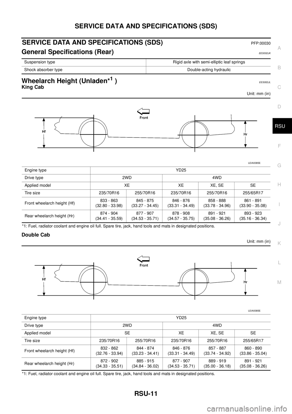
Wheelarch Height (Unladen*1)EES002JL
King Cab
Unit: mm (in)
*1: Fuel, radiator coolant and engine oil full. Spare tire, jack, hand tools and mats in designated positions.
Double Cab
Unit: mm (in)
*1: Fuel, radiator coolant and engine oil full. Spare tire, jack, hand tools and mats in designated positions.Suspension type Rigid axle with semi-elliptic leaf springs
Shock absorber type Double-acting hydraulic
Engine type YD25
Drive type 2WD 4WD
Applied model XE XE XE, SE SE
Tire size 235/70R16 255/70R16 235/70R16 255/70R16 255/65R17
Front wheelarch height (Hf)833 - 863
(32.80 - 33.98)845 - 875
(33.27 - 34.45)846 - 876
(33.31 - 34.49)858 - 888
(33.78 - 34.96)861 - 891
(33.90 - 35.08)
Rear wheelarch height (Hr)874 - 904
(34.41 - 35.59)877 - 907
(34.53 - 35.71)878 - 908
(34.57 - 35.75)891 - 921
(35.08 - 36.26)893 - 923
(35.16 - 36.34)
LEIA0085E
Engine type YD25
Drive type 2WD 4WD
Applied model SE XE XE, SE SE
Tire size 235/70R16 255/70R16 235/70R16 255/70R16 255/65R17
Front wheelarch height (Hf)832 - 862
(32.76 - 33.94)844 - 874
(33.23 - 34.41)846 - 876
(33.31 - 34.49)857 - 887
(33.74 - 34.92)860 - 890
(33.86 - 35.04)
Rear wheelarch height (Hr)872 - 902
(34.33 - 35.51)885 - 915
(34.84 - 36.02)877 - 907
(34.53 - 35.71)889 - 919
(35.00 - 36.18)891 - 921
(35.08 - 36.26)
LEIA0085E