tow bar NISSAN NAVARA 2005 Repair Workshop Manual
[x] Cancel search | Manufacturer: NISSAN, Model Year: 2005, Model line: NAVARA, Model: NISSAN NAVARA 2005Pages: 3171, PDF Size: 49.59 MB
Page 1433 of 3171
![NISSAN NAVARA 2005 Repair Workshop Manual FUEL PUMP
EM-51
C
D
E
F
G
H
I
J
K
L
MA
EM
8. Using the sprocket holder [SST], hold fuel pump sprocket to pre-
vent falling.
lFor sprocket holder, use KV11106060 machined as shown in
the figure, becaus NISSAN NAVARA 2005 Repair Workshop Manual FUEL PUMP
EM-51
C
D
E
F
G
H
I
J
K
L
MA
EM
8. Using the sprocket holder [SST], hold fuel pump sprocket to pre-
vent falling.
lFor sprocket holder, use KV11106060 machined as shown in
the figure, becaus](/img/5/57362/w960_57362-1432.png)
FUEL PUMP
EM-51
C
D
E
F
G
H
I
J
K
L
MA
EM
8. Using the sprocket holder [SST], hold fuel pump sprocket to pre-
vent falling.
lFor sprocket holder, use KV11106060 machined as shown in
the figure, because the previous bore is not fitting.
lWhen the sprocket holder is installed, if the positioning stop-
per pin [SST] interferes, pull out the positioning stopper pin
approximately 10 mm (0.39 in), then install it.
lAfter the sprocket holder is installed temporarily, tighten the
sprocket holder after making extension bar and TORX socket
(size: E10) (commercial service tool) insert into the machined
bore.
lThe length of the sprocket holder mounting bolts should be
approximately 15 mm (0.59 in) (M6 thread length).
lMake sure that the a- and b-faces of the sprocket holder con-
tact the bottom side of the sprocket (small diameter side).
CAUTION:
Do not remove the sprocket holder [SST] until fuel pump is installed.
lAfter the sprocket holder is installed, pull out the positioning
stopper pin from fuel pump sprocket.
9. Using the extension bar and the TORX socket (size: E10) (com-
mercial service tool), remove the tightening bolts.
CAUTION:
Do not disassemble or adjust fuel pump.
10. Remove the fuel pump toward the rear of engine.
CAUTION:
For removal, be careful not to drop the seal washer into the engine.
NOTE:
The seal washer of the tightening bolts cannot be reused.
11. Remove adjusting shim.
12. Attach a suitable tool in the M8 bolt hole on coupling.
SBIA0217E
PBIC2534E
MBIA0075E
PBIC2405E
Page 1610 of 3171

FSU-10
COIL SPRING AND SHOCK ABSORBER
COIL SPRING AND SHOCK ABSORBER
PFP:56210
Removal and InstallationEES002KO
REMOVAL
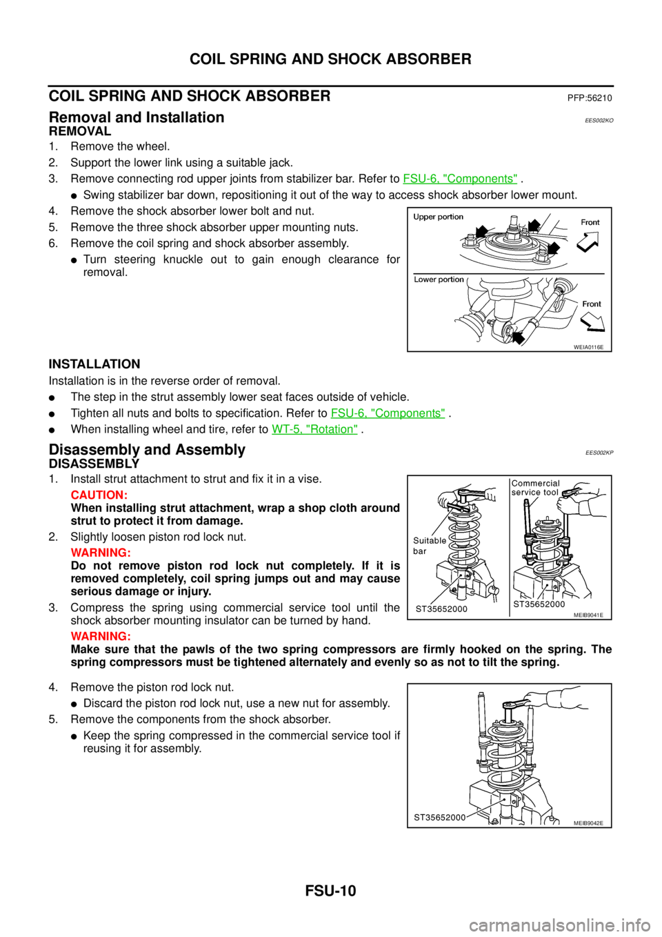
1. Remove the wheel.
2. Support the lower link using a suitable jack.
3. Remove connecting rod upper joints from stabilizer bar. Refer toFSU-6, "
Components".
lSwing stabilizer bar down, repositioning it out of the way to access shock absorber lower mount.
4. Remove the shock absorber lower bolt and nut.
5. Remove the three shock absorber upper mounting nuts.
6. Remove the coil spring and shock absorber assembly.
lTurn steering knuckle out to gain enough clearance for
removal.
INSTALLATION
Installation is in the reverse order of removal.
lThe step in the strut assembly lower seat faces outside of vehicle.
lTighten all nuts and bolts to specification. Refer toFSU-6, "Components".
lWhen installing wheel and tire, refer toWT-5, "Rotation".
Disassembly and AssemblyEES002KP
DISASSEMBLY
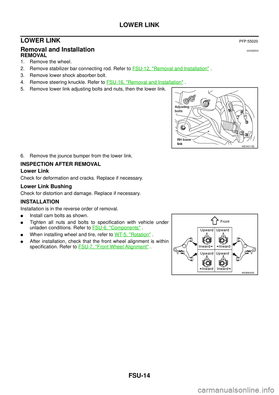
1. Install strut attachment to strut and fix it in a vise.
CAUTION:
When installing strut attachment, wrap a shop cloth around
strut to protect it from damage.
2. Slightly loosen piston rod lock nut.
WARNING:
Do not remove piston rod lock nut completely. If it is
removed completely, coil spring jumps out and may cause
serious damage or injury.
3. Compress the spring using commercial service tool until the
shock absorber mounting insulator can be turned by hand.
WARNING:
Make sure that the pawls of the two spring compressors are firmly hooked on the spring. The
spring compressors must be tightened alternately and evenly so as not to tilt the spring.
4. Remove the piston rod lock nut.
lDiscard the piston rod lock nut, use a new nut for assembly.
5. Remove the components from the shock absorber.
lKeep the spring compressed in the commercial service tool if
reusing it for assembly.
WEIA0116E
MEIB9041E
MEIB9042E
Page 1614 of 3171

FSU-14
LOWER LINK
LOWER LINK
PFP:55020
Removal and InstallationEES002KS
REMOVAL
1. Remove the wheel.
2. Remove stabilizer bar connecting rod. Refer toFSU-12, "
Removal and Installation".
3. Remove lower shock absorber bolt.
4. Remove steering knuckle. Refer toFSU-16, "
Removal and Installation".
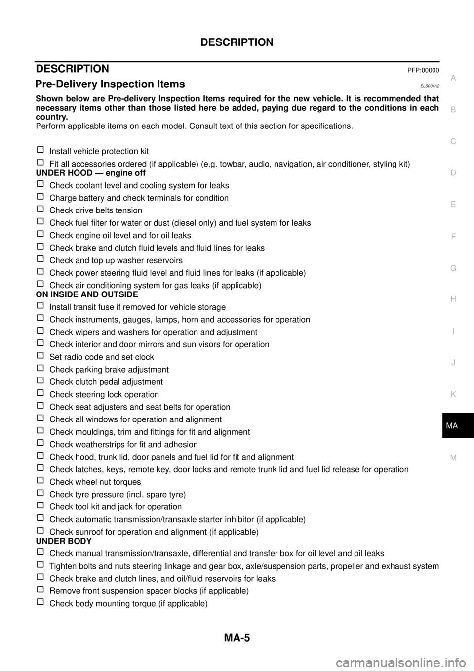
5. Remove lower link adjusting bolts and nuts, then the lower link.
6. Remove the jounce bumper from the lower link.
INSPECTION AFTER REMOVAL
Lower Link
Check for deformation and cracks. Replace if necessary.
Lower Link Bushing
Check for distortion and damage. Replace if necessary.
INSTALLATION
Installation is in the reverse order of removal.
lInstall cam bolts as shown.
lTighten all nuts and bolts to specification with vehicle under
unladen conditions. Refer toFSU-6, "
Components".
lWhen installing wheel and tire, refer toWT-5, "Rotation".
lAfter installation, check that the front wheel alignment is within
specification. Refer toFSU-7, "
Front Wheel Alignment".
WEIA0115E
MEIB9043E
Page 2280 of 3171

DESCRIPTION
MA-5
C
D
E
F
G
H
I
J
K
MA
B
MA
DESCRIPTIONPFP:00000
Pre-Delivery Inspection ItemsELS001K2
Shown below are Pre-delivery Inspection Items required for the new vehicle. It is recommended that
necessary items other than those listed here be added, paying due regard to the conditions in each
country.
Perform applicable items on each model. Consult text of this section for specifications.
Install vehicle protection kit
Fit all accessories ordered (if applicable) (e.g. towbar, audio, navigation, air conditioner, styling kit)
UNDER HOOD — engine off
Check coolant level and cooling system for leaks
Charge battery and check terminals for condition
Check drive belts tension
Check fuel filter for water or dust (diesel only) and fuel system for leaks
Check engine oil level and for oil leaks
Check brake and clutch fluid levels and fluid lines for leaks
Check and top up washer reservoirs
Check power steering fluid level and fluid lines for leaks (if applicable)
Check air conditioning system for gas leaks (if applicable)
ON INSIDE AND OUTSIDE
Install transit fuse if removed for vehicle storage
Check instruments, gauges, lamps, horn and accessories for operation
Check wipers and washers for operation and adjustment
Check interior and door mirrors and sun visors for operation
Set radio code and set clock
Check parking brake adjustment
Check clutch pedal adjustment
Check steering lock operation
Check seat adjusters and seat belts for operation
Check all windows for operation and alignment
Check mouldings, trim and fittings for fit and alignment
Check weatherstrips for fit and adhesion
Check hood, trunk lid, door panels and fuel lid for fit and alignment
Check latches, keys, remote key, door locks and remote trunk lid and fuel lid release for operation
Check wheel nut torques
Check tyre pressure (incl. spare tyre)
Check tool kit and jack for operation
Check automatic transmission/transaxle starter inhibitor (if applicable)
Check sunroof for operation and alignment (if applicable)
UNDER BODY
Check manual transmission/transaxle, differential and transfer box for oil level and oil leaks
Tighten bolts and nuts steering linkage and gear box, axle/suspension parts, propeller and exhaust system
Check brake and clutch lines, and oil/fluid reservoirs for leaks
Remove front suspension spacer blocks (if applicable)
Check body mounting torque (if applicable)