Panel control AC NISSAN NAVARA 2005 Repair Workshop Manual
[x] Cancel search | Manufacturer: NISSAN, Model Year: 2005, Model line: NAVARA, Model: NISSAN NAVARA 2005Pages: 3171, PDF Size: 49.59 MB
Page 1 of 3171
MODELD40 SERIES
2005 NISSAN EUROPE S.A.S.
All rights reserved. No part of this Electronic Service Manual may be reproduced or stored in a retrieval system, or transmitted in any
form, or by any means, electronic, mechanical, photocopying, recording or otherwise, without the prior written permission of Nissan
Europe S.A.S., Paris, France.
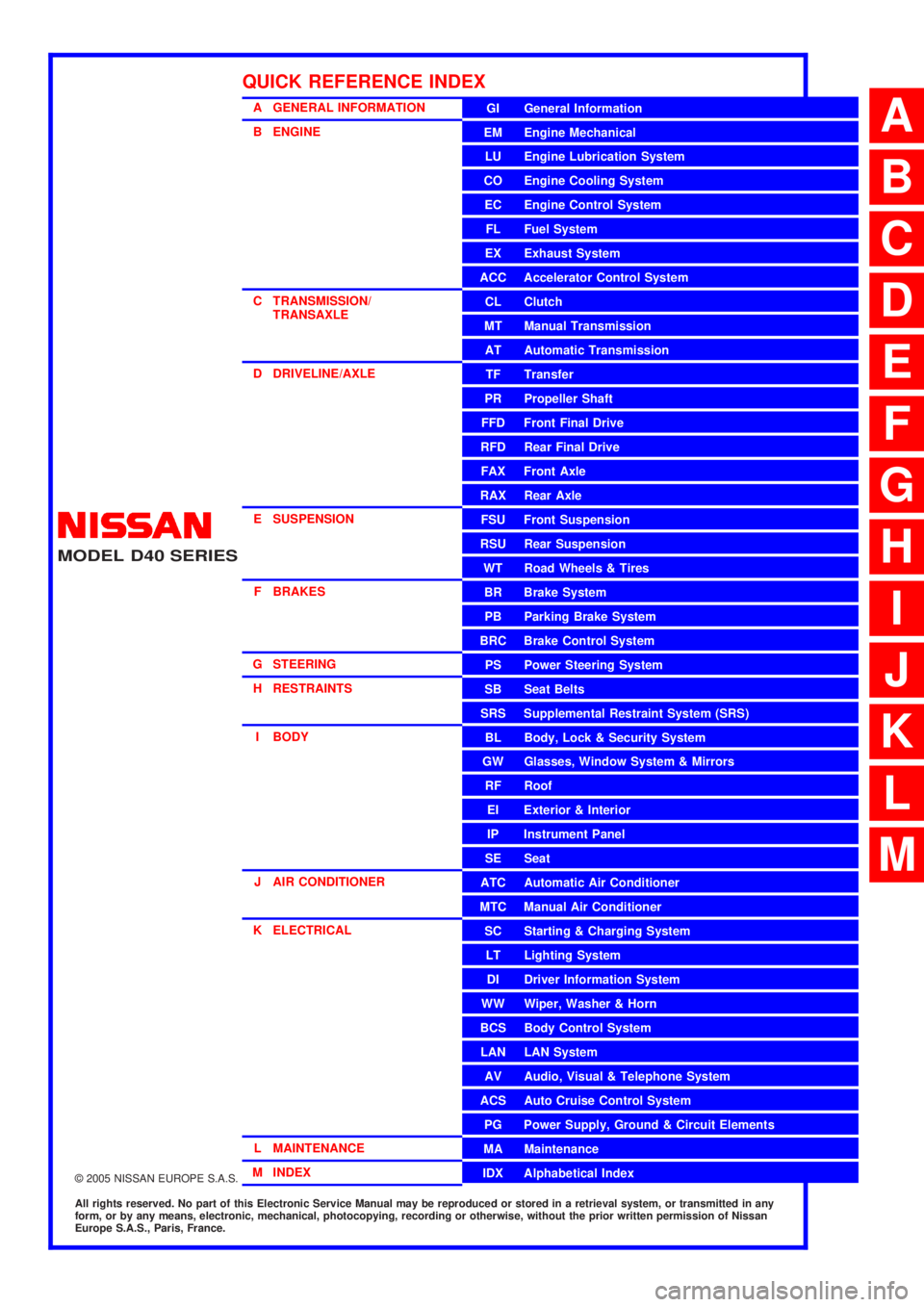
A GENERAL INFORMATION
B ENGINE
C TRANSMISSION/TRANSAXLE
D DRIVELINE/AXLE
E SUSPENSION F BRAKES
G STEERING H RESTRAINTS
I BODY
J AIR CONDITIONER
K ELECTRICAL
L MAINTENANCE
M INDEXGI General Information
EM Engine Mechanical
LU Engine Lubrication System
CO Engine Cooling System
EC Engine Control System
FL Fuel System
EX Exhaust System
ACC Accelerator Control System
CL Clutch
MTManualTransmission
AT Automatic Transmission
TF Transfer
PR Propeller Shaft
FFD Front Final Drive
RFD Rear Final Drive
FAX Front Axle
RAX Rear Axle
FSU Front Suspension
RSU Rear Suspension
WT Road Wheels & Tires
BR Brake System
PB Parking Brake System
BRC Brake Control System
PS Power Steering System
SB Seat Belts
SRS Supplemental Restraint System (SRS)
BL Body, Lock & Security System
GW Glasses, Window System & Mirrors
RF Roof
EI Exterior & Interior
IP Instrument Panel
SE Seat
ATC Automatic Air Conditioner
MTC Manual Air Conditioner
SC Starting & Charging System
LT Lighting System
DI Driver Information System
WW Wiper, Washer & Horn
BCS Body Control System
LAN LAN System
AV Audio, Visual & Telephone System
ACS Auto Cruise Control System
PG Power Supply, Ground & Circuit Elements
MA Maintenance
IDX Alphabetical Index
QUICK REFERENCE INDEX
A
B
C
D
E
F
G
H
I
J
K
L
M
Page 87 of 3171
TROUBLE DIAGNOSIS
AT-79
D
E
F
G
H
I
J
K
L
MA
B
AT
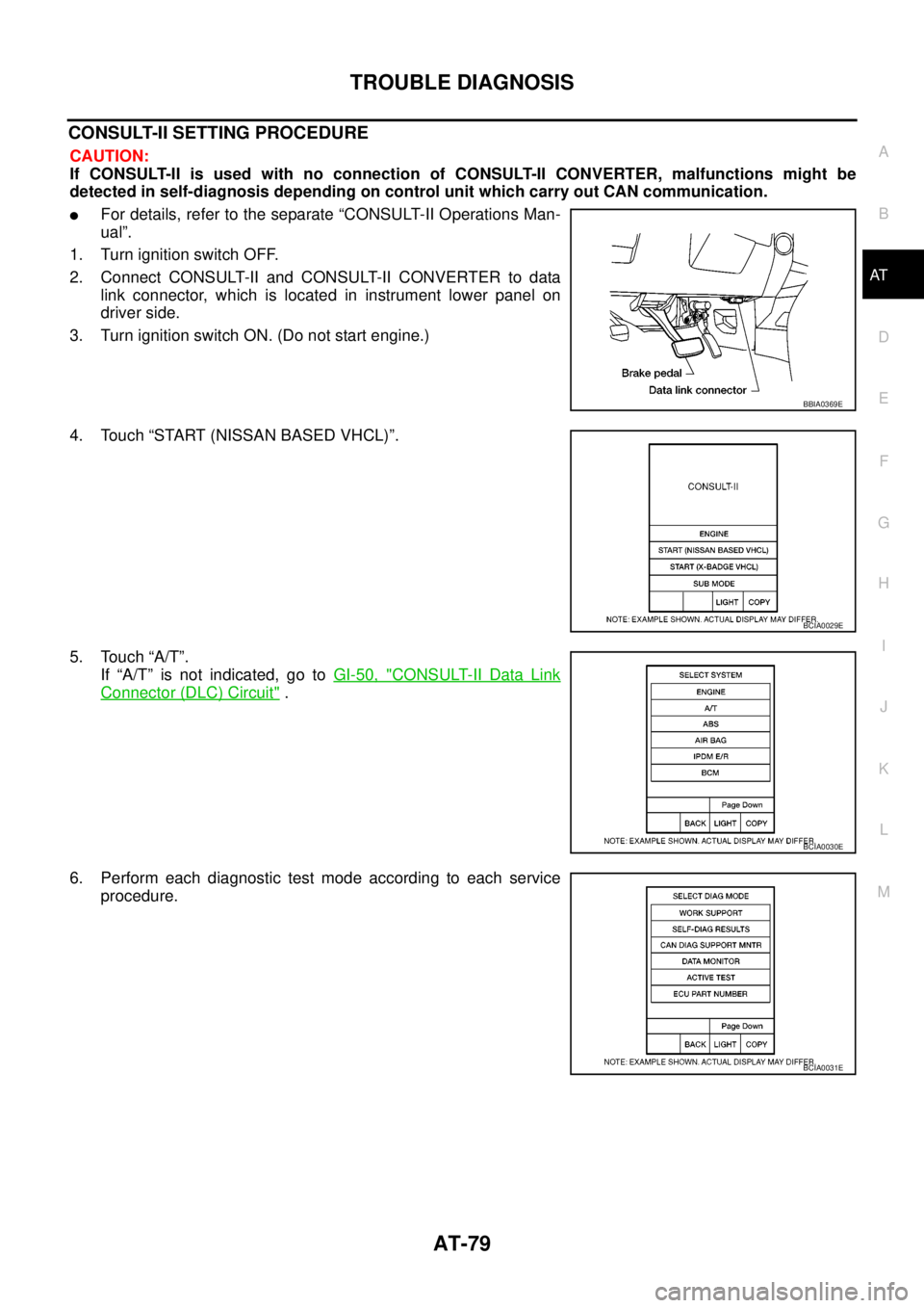
CONSULT-II SETTING PROCEDURE
CAUTION:
If CONSULT-II is used with no connection of CONSULT-II CONVERTER, malfunctions might be
detected in self-diagnosis depending on control unit which carry out CAN communication.
lFor details, refer to the separate “CONSULT-II Operations Man-
ual”.
1. Turn ignition switch OFF.
2. Connect CONSULT-II and CONSULT-II CONVERTER to data
link connector, which is located in instrument lower panel on
driver side.
3. Turn ignition switch ON. (Do not start engine.)
4. Touch “START (NISSAN BASED VHCL)”.
5. Touch “A/T”.
If “A/T” is not indicated, go toGI-50, "
CONSULT-II Data Link
Connector (DLC) Circuit".
6. Perform each diagnostic test mode according to each service
procedure.
BBIA0369E
BCIA0029E
BCIA0030E
BCIA0031E
Page 218 of 3171
AT-210
SHIFT CONTROL SYSTEM
Control Cable Removal and Installation
ECS00G55
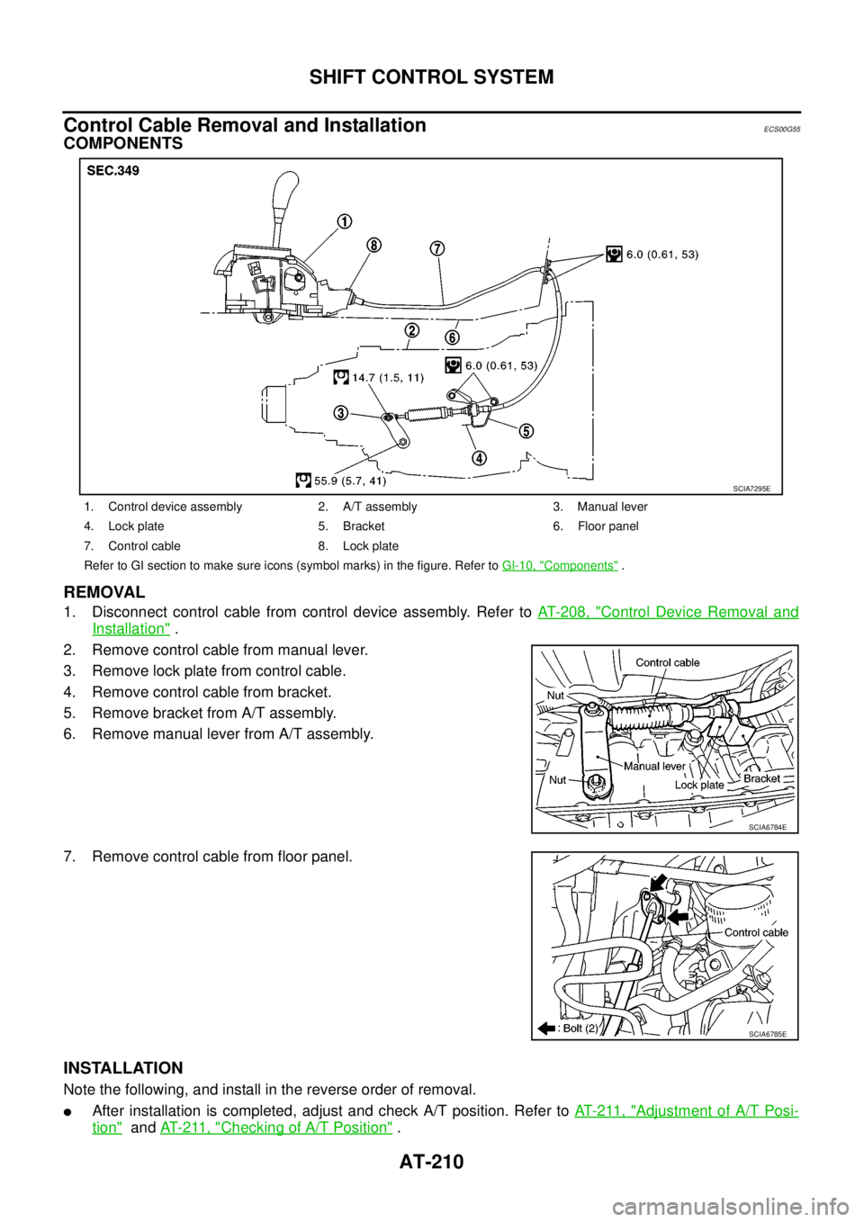
COMPONENTS
REMOVAL
1. Disconnect control cable from control device assembly. Refer toAT- 2 0 8 , "Control Device Removal and
Installation".
2. Remove control cable from manual lever.
3. Remove lock plate from control cable.
4. Remove control cable from bracket.
5. Remove bracket from A/T assembly.
6. Remove manual lever from A/T assembly.
7. Remove control cable from floor panel.
INSTALLATION
Note the following, and install in the reverse order of removal.
lAfter installation is completed, adjust and check A/T position. Refer toAT- 2 11 , "Adjustment of A/T Posi-
tion"andAT- 2 11 , "Checking of A/T Position".
1. Control device assembly 2. A/T assembly 3. Manual lever
4. Lock plate 5. Bracket 6. Floor panel
7. Control cable 8. Lock plate
Refer to GI section to make sure icons (symbol marks) in the figure. Refer toGI-10, "
Components".
SCIA7295E
SCIA6784E
SCIA6785E
Page 225 of 3171
KEY INTERLOCK CABLE
AT-217
D
E
F
G
H
I
J
K
L
MA
B
AT
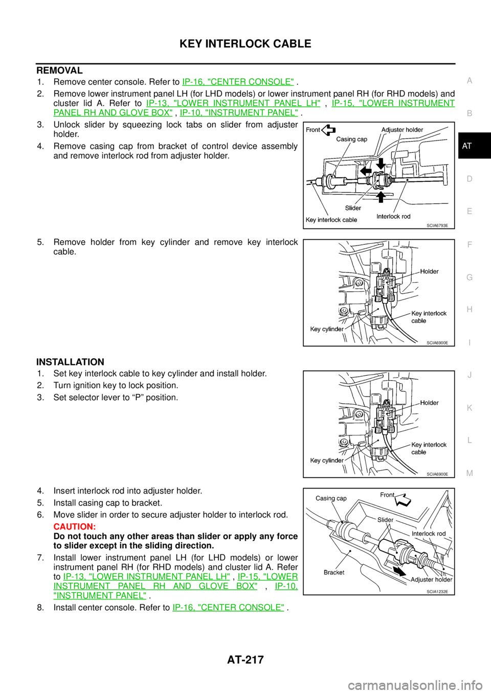
REMOVAL
1. Remove center console. Refer toIP-16, "CENTER CONSOLE".
2. Remove lower instrument panel LH (for LHD models) or lower instrument panel RH (for RHD models) and
cluster lid A. Refer toIP-13, "
LOWER INSTRUMENT PANEL LH",IP-15, "LOWER INSTRUMENT
PANEL RH AND GLOVE BOX",IP-10, "INSTRUMENT PANEL".
3. Unlock slider by squeezing lock tabs on slider from adjuster
holder.
4. Remove casing cap from bracket of control device assembly
and remove interlock rod from adjuster holder.
5. Remove holder from key cylinder and remove key interlock
cable.
INSTALLATION
1. Set key interlock cable to key cylinder and install holder.
2. Turn ignition key to lock position.
3. Set selector lever to “P” position.
4. Insert interlock rod into adjuster holder.
5. Install casing cap to bracket.
6. Move slider in order to secure adjuster holder to interlock rod.
CAUTION:
Do not touch any other areas than slider or apply any force
to slider except in the sliding direction.
7. Install lower instrument panel LH (for LHD models) or lower
instrument panel RH (for RHD models) and cluster lid A. Refer
toIP-13, "
LOWER INSTRUMENT PANEL LH",IP-15, "LOWER
INSTRUMENT PANEL RH AND GLOVE BOX",IP-10,
"INSTRUMENT PANEL".
8. Install center console. Refer toIP-16, "
CENTER CONSOLE".
SCIA6793E
SCIA6900E
SCIA6900E
SCIA1232E
Page 442 of 3171
ATC-108
TROUBLE DIAGNOSIS
In-vehicle Sensor Circuit
EJS006BX
COMPONENT DESCRIPTION
In-vehicle Sensor
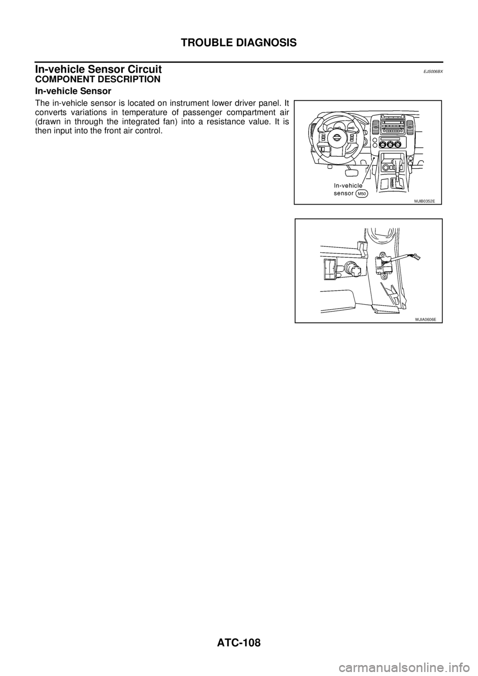
The in-vehicle sensor is located on instrument lower driver panel. It
converts variations in temperature of passenger compartment air
(drawn in through the integrated fan) into a resistance value. It is
then input into the front air control.
MJIB0352E
WJIA0606E
Page 456 of 3171
ATC-122
AIR CONDITIONER FILTER
AIR CONDITIONER FILTER
PFP:27277
Removal and InstallationEJS006C7
FUNCTION
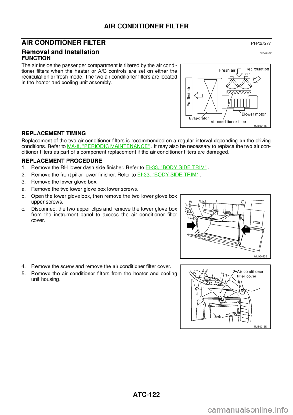
The air inside the passenger compartment is filtered by the air condi-
tioner filters when the heater or A/C controls are set on either the
recirculation or fresh mode. The two air conditioner filters are located
in the heater and cooling unit assembly.
REPLACEMENT TIMING
Replacement of the two air conditioner filters is recommended on a regular interval depending on the driving
conditions. Refer toMA-8, "
PERIODIC MAINTENANCE". It may also be necessary to replace the two air con-
ditioner filters as part of a component replacement if the air conditioner filters are damaged.
REPLACEMENT PROCEDURE
1. Remove the RH lower dash side finisher. Refer toEI-33, "BODY SIDE TRIM".
2. Remove the front pillar lower finisher. Refer toEI-33, "
BODY SIDE TRIM".
3. Remove the lower glove box.
a. Remove the two lower glove box lower screws.
b. Open the lower glove box, then remove the two lower glove box
upper screws.
c. Disconnect the two upper clips and remove the lower glove box
from the instrument panel to access the air conditioner filter
cover.
4. Remove the screw and remove the air conditioner filter cover.
5. Remove the air conditioner filters from the heater and cooling
unit housing.
MJIB0215E
WLIA0023E
MJIB0216E
Page 464 of 3171
ATC-130
MODE DOOR MOTOR
MODE DOOR MOTOR
PFP:27731
ComponentsEJS006CE
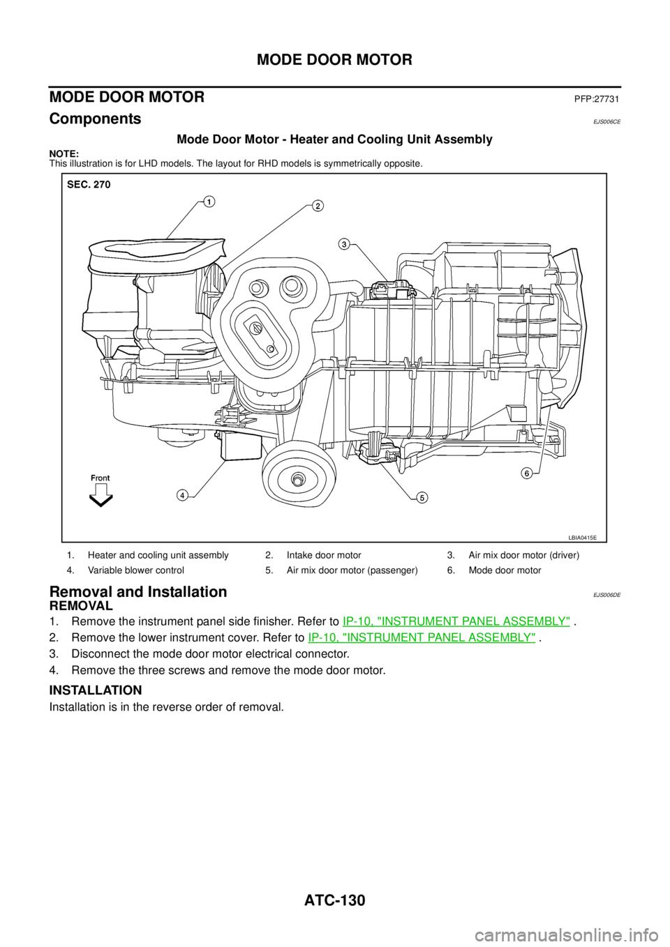
Mode Door Motor - Heater and Cooling Unit Assembly
NOTE:
This illustration is for LHD models. The layout for RHD models is symmetrically opposite.
Removal and InstallationEJS006DE
REMOVAL
1. Remove the instrument panel side finisher. Refer toIP-10, "INSTRUMENT PANEL ASSEMBLY".
2. Remove the lower instrument cover. Refer toIP-10, "
INSTRUMENT PANEL ASSEMBLY".
3. Disconnect the mode door motor electrical connector.
4. Remove the three screws and remove the mode door motor.
INSTALLATION
Installation is in the reverse order of removal.
1. Heater and cooling unit assembly 2. Intake door motor 3. Air mix door motor (driver)
4. Variable blower control 5. Air mix door motor (passenger) 6. Mode door motor
LBIA0415E
Page 465 of 3171
AIR MIX DOOR MOTOR
ATC-131
C
D
E
F
G
H
I
K
L
MA
B
AT C
AIR MIX DOOR MOTORPFP:27732
ComponentsEJS006CF
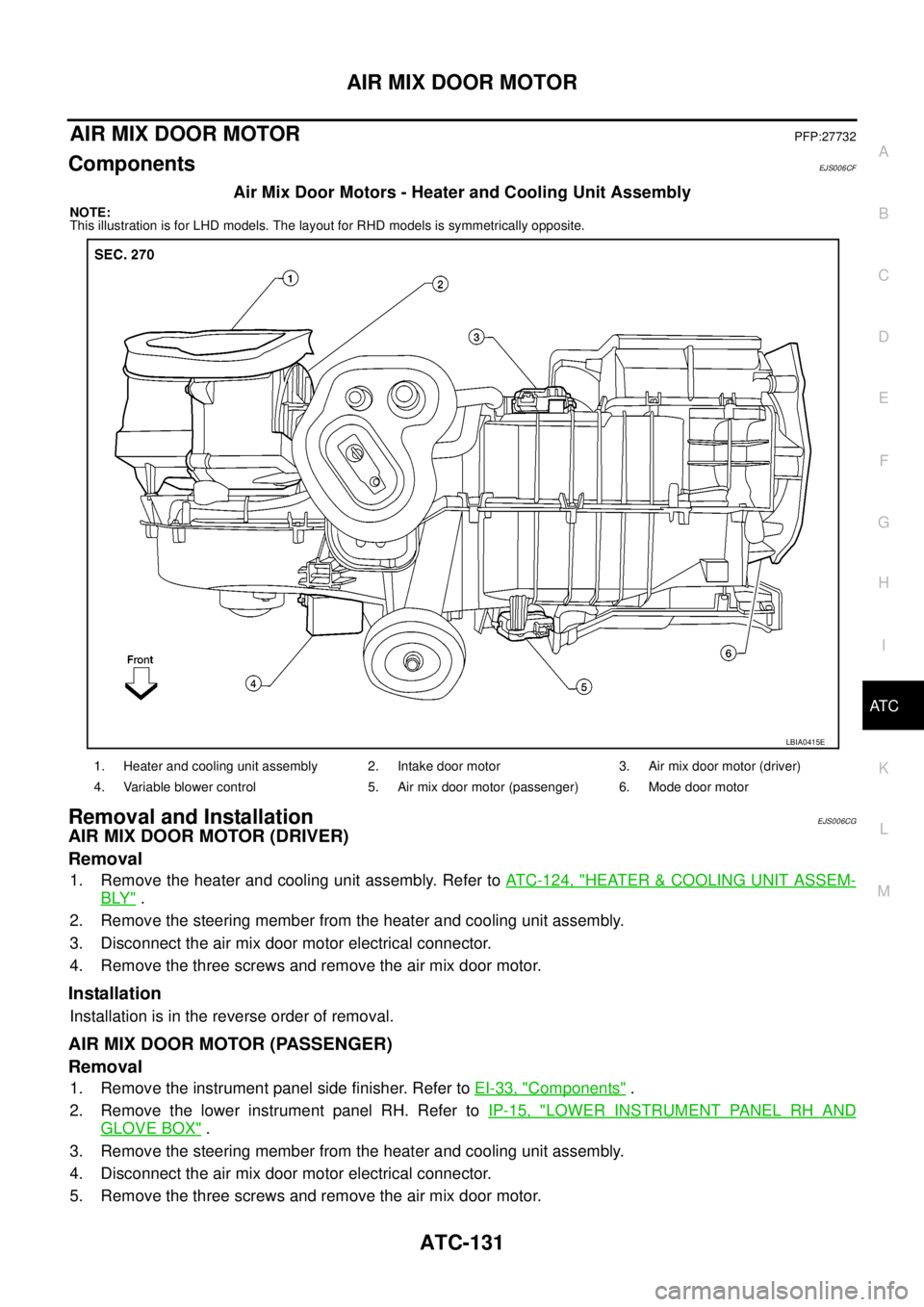
Air Mix Door Motors - Heater and Cooling Unit Assembly
NOTE:
This illustration is for LHD models. The layout for RHD models is symmetrically opposite.
Removal and InstallationEJS006CG
AIR MIX DOOR MOTOR (DRIVER)
Removal
1. Remove the heater and cooling unit assembly. Refer toATC-124, "HEATER&COOLING UNIT ASSEM-
BLY".
2. Remove the steering member from the heater and cooling unit assembly.
3. Disconnect the air mix door motor electrical connector.
4. Remove the three screws and remove the air mix door motor.
Installation
Installation is in the reverse order of removal.
AIR MIX DOOR MOTOR (PASSENGER)
Removal
1. Remove the instrument panel side finisher. Refer toEI-33, "Components".
2. Remove the lower instrument panel RH. Refer toIP-15, "
LOWER INSTRUMENT PANEL RH AND
GLOVE BOX".
3. Remove the steering member from the heater and cooling unit assembly.
4. Disconnect the air mix door motor electrical connector.
5. Remove the three screws and remove the air mix door motor.
1. Heater and cooling unit assembly 2. Intake door motor 3. Air mix door motor (driver)
4. Variable blower control 5. Air mix door motor (passenger) 6. Mode door motor
LBIA0415E
Page 496 of 3171
AV-8
SYSTEM DESCRIPTION
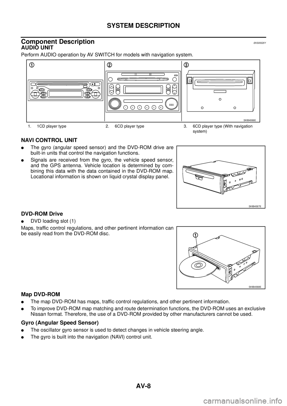
Component Description
EKS00Q5Y
AUDIO UNIT
Perform AUDIO operation by AV SWITCH for models with navigation system.
NAVI CONTROL UNIT
lThe gyro (angular speed sensor) and the DVD-ROM drive are
built-in units that control the navigation functions.
lSignals are received from the gyro, the vehicle speed sensor,
and the GPS antenna. Vehicle location is determined by com-
bining this data with the data contained in the DVD-ROM map.
Locational information is shown on liquid crystal display panel.
DVD-ROM Drive
lDVD loading slot (1)
Maps, traffic control regulations, and other pertinent information can
be easily read from the DVD-ROM disc.
Map DVD-ROM
lThe map DVD-ROM has maps, traffic control regulations, and other pertinent information.
lTo improve DVD-ROM map matching and route determination functions, the DVD-ROM uses an exclusive
Nissan format. Therefore, the use of a DVD-ROM provided by other manufacturers cannot be used.
Gyro (Angular Speed Sensor)
lThe oscillator gyro sensor is used to detect changes in vehicle steering angle.
lThe gyro is built into the navigation (NAVI) control unit.
1. 1CD player type 2. 6CD player type 3. 6CD player type (With navigation
system)
SKIB4066E
SKIB4067E
SKIB4068E
Page 497 of 3171
SYSTEM DESCRIPTION
AV-9
C
D
E
F
G
H
I
J
L
MA
B
AV
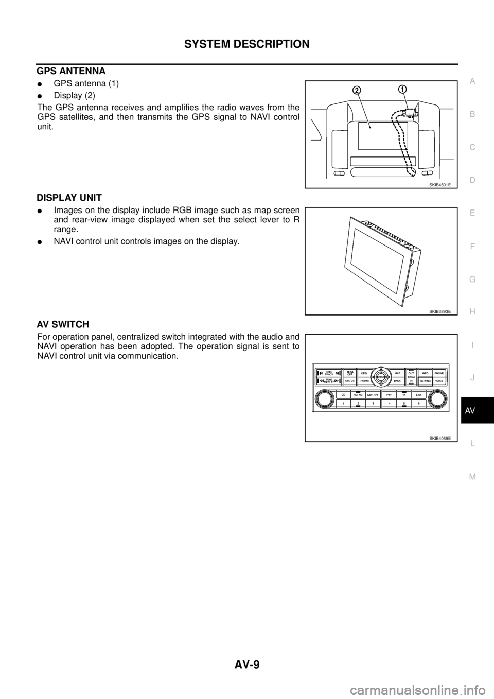
GPS ANTENNA
lGPS antenna (1)
lDisplay (2)
The GPS antenna receives and amplifies the radio waves from the
GPS satellites, and then transmits the GPS signal to NAVI control
unit.
DISPLAY UNIT
lImages on the display include RGB image such as map screen
and rear-view image displayed when set the select lever to R
range.
lNAVI control unit controls images on the display.
AV S W I T C H
For operation panel, centralized switch integrated with the audio and
NAVI operation has been adopted. The operation signal is sent to
NAVI control unit via communication.
SKIB4501E
SKIB3893E
SKIB4069E