air bleeding NISSAN NAVARA 2005 Repair Workshop Manual
[x] Cancel search | Manufacturer: NISSAN, Model Year: 2005, Model line: NAVARA, Model: NISSAN NAVARA 2005Pages: 3171, PDF Size: 49.59 MB
Page 787 of 3171

BR-1
BRAKE SYSTEM
F BRAKES
CONTENTS
C
D
E
G
H
I
J
K
L
M
SECTIONBR
A
B
BR
BRAKE SYSTEM
PRECAUTIONS .......................................................... 3
Precautions for Supplemental Restraint System
(SRS)“AIRBAG”and“SEATBELTPRE-TEN-
SIONER” .................................................................. 3
Precautions for Brake System .................................. 3
PREPARATION ........................................................... 4
Special Service Tools ............................................... 4
Commercial Service Tools ........................................ 4
NOISE, VIBRATION AND HARSHNESS (NVH)
TROUBLESHOOTING ................................................ 5
NVH Troubleshooting Chart ..................................... 5
BRAKE PEDAL .......................................................... 6
Inspection and Adjustment ....................................... 6
ADJUSTMENT ...................................................... 7
Removal and Installation .......................................... 8
COMPONENTS .................................................... 8
REMOVAL ............................................................. 8
INSPECTION AFTER REMOVAL ......................... 9
INSTALLATION ..................................................... 9
BRAKE FLUID .......................................................... 10
On-board Inspection ............................................... 10
CHECKING BRAKE FLUID LEVEL .................... 10
Drain and Refill ....................................................... 10
Bleeding Brake System ........................................... 11
LHD MODEL ........................................................ 11
RHD MODEL ........................................................ 11
BRAKE TUBE AND HOSE ....................................... 12
Hydraulic Circuit ..................................................... 12
Removal and Installation of Front Brake Tube and
Brake Hose ............................................................ 13
REMOVAL ........................................................... 13
INSTALLATION ................................................... 13
Removal and Installation of Rear Brake Tube and
Brake Hose ............................................................ 13
REMOVAL ........................................................... 13
INSTALLATION ................................................... 13
Inspection after Installation .................................... 14
LOAD SENSING VALVE .......................................... 15
Removal and Installation ........................................ 15
REMOVAL ........................................................... 15INSTALLATION ................................................... 15
Inspection ............................................................... 16
INSPECTION ...................................................... 16
BRAKE MASTER CYLINDER .................................. 17
On-Board Inspection ............................................... 17
LEAK INSPECTION ............................................ 17
Removal and Installation ........................................ 17
REMOVAL ........................................................... 17
INSTALLATION ................................................... 17
Components ........................................................... 17
Disassembly and Assembly .................................... 18
DISASSEMBLY ................................................... 18
ASSEMBLY ......................................................... 18
BRAKE BOOSTER ................................................... 19
On-Vehicle Service ................................................. 19
OPERATING CHECK .......................................... 19
AIRTIGHT CHECK .............................................. 19
Removal and Installation ........................................ 20
COMPONENTS ................................................... 20
REMOVAL ........................................................... 20
INSPECTION AFTER REMOVAL ....................... 20
INSTALLATION ................................................... 21
VACUUM LINES ....................................................... 22
Component ............................................................. 22
Removal and Installation ........................................ 23
Inspection ............................................................... 23
VISUAL INSPECTION ......................................... 23
CHECK VALVE INSPECTION ............................. 23
FRONT DISC BRAKE ............................................... 24
On-Board Inspection ............................................... 24
PAD WEAR INSPECTION ................................... 24
Components ........................................................... 24
Removal and Installation of Brake Pad .................. 25
REMOVAL ........................................................... 25
INSTALLATION ................................................... 25
Removal and Installation of Brake Caliper Assembly
... 26
REMOVAL ........................................................... 26
INSTALLATION ................................................... 26
Disassembly and Assembly of Brake Caliper
Page 796 of 3171
BR-10
BRAKE FLUID
BRAKE FLUID
PFP:KN100
On-board InspectionEFS005SI
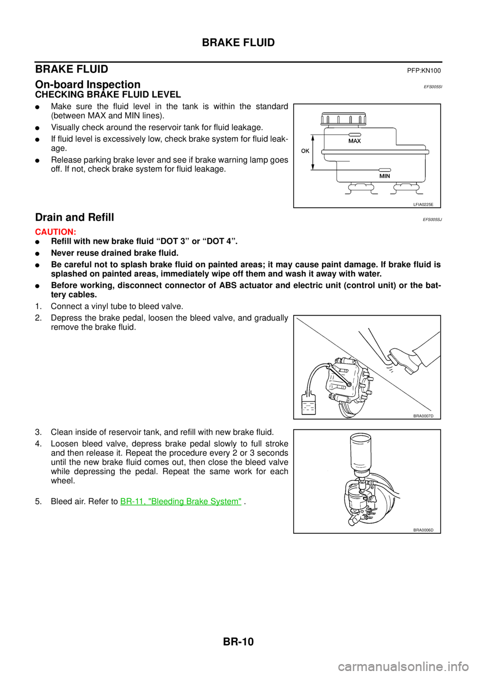
CHECKING BRAKE FLUID LEVEL
lMake sure the fluid level in the tank is within the standard
(between MAX and MIN lines).
lVisually check around the reservoir tank for fluid leakage.
lIf fluid level is excessively low, check brake system for fluid leak-
age.
lRelease parking brake lever and see if brake warning lamp goes
off. If not, check brake system for fluid leakage.
Drain and RefillEFS005SJ
CAUTION:
lRefill with new brake fluid “DOT 3” or “DOT 4”.
lNever reuse drained brake fluid.
lBe careful not to splash brake fluid on painted areas; it may cause paint damage. If brake fluid is
splashed on painted areas, immediately wipe off them and wash it away with water.
lBefore working, disconnect connector of ABS actuator and electric unit (control unit) or the bat-
tery cables.
1. Connect a vinyl tube to bleed valve.
2. Depress the brake pedal, loosen the bleed valve, and gradually
remove the brake fluid.
3. Clean inside of reservoir tank, and refill with new brake fluid.
4. Loosen bleed valve, depress brake pedal slowly to full stroke
and then release it. Repeat the procedure every 2 or 3 seconds
until the new brake fluid comes out, then close the bleed valve
while depressing the pedal. Repeat the same work for each
wheel.
5. Bleed air. Refer toBR-11, "
Bleeding Brake System".
LFIA0225E
BRA0007D
BRA0006D
Page 797 of 3171
BRAKE FLUID
BR-11
C
D
E
G
H
I
J
K
L
MA
B
BR
Bleeding Brake SystemEFS005SK
CAUTION:
lWhile bleeding, pay attention to master cylinder fluid level.
lBefore working, disconnect electrical connector of ABS actuator and electric unit (control unit) or
the battery cable from the negative terminal.
LHD MODEL
1. Connect a vinyl tube to the rear right bleed valve.
2. Fully depress brake pedal 4 to 5 times.
3. With brake pedal depressed, loosen bleed valve to let the air out, and then tighten it immediately.
4. Repeat steps 3, 4 until no more air comes out.
5. Tighten bleed valve to specified torque. Refer toBR-24, "
Components"(front disc brake),BR-30, "Com-
ponents"(rear drum brake).
6. From the steps 1 to 5 above, with master cylinder reservoir tank filled at least half way, bleed air from the
front left, rear left, and front right brake, in that order.
RHD MODEL
1. Connect a vinyl tube to the rear left bleed valve.
2. Fully depress brake pedal 4 to 5 times.
3. With brake pedal depressed, loosen bleed valve to let the air out, and then tighten it immediately.
4. Repeat steps 3, 4 until no more air comes out.
5. Tighten bleed valve to specified torque. Refer toBR-24, "
Components"(front disc brake),BR-30, "Com-
ponents"(rear drum brake).
6. From the steps 1 to 5 above, with master cylinder reservoir tank filled at least half way, bleed air from the
front right, rear right, and front left brake, in that order.
Page 799 of 3171
BRAKE TUBE AND HOSE
BR-13
C
D
E
G
H
I
J
K
L
MA
B
BR
CAUTION:
lAll brake tubes and hoses must be free from excessive bending, twisting and pulling.
lMake sure that there is no interference with other parts when turning steering both clockwise and
counterclockwise.
lBrake tube and hose is an important safety part. Always disassemble the parts and retighten their
fittings, if a brake fluid leak is detected. Replace applicable part with a new one, if damaged part is
detected.
lBe careful not to splash brake fluid on painted areas; it may cause paint damage. If brake fluid is
splashed on painted surfaces of body, immediately wipe off them and wash it away with water.
lDo not bend or twist brake hose sharply, or strongly pull it.
lCover the open end of brake tube and hoses when disconnecting to prevent entrance of dirt.
lRefill with new brake fluid “DOT 3” or “DOT 4”.
lNever reuse drained brake fluid.
Removal and Installation of Front Brake Tube and Brake HoseEFS005SM
REMOVAL
1. Drain brake fluid. Refer toBR-10, "Drain and Refill".
2. Using a flare nut wrench, disconnect brake tube from brake hose.
3. Remove union bolt and remove brake hose from caliper assembly.
4. Remove lock plate and remove brake hose from vehicle.
INSTALLATION
1. Assemble the union bolt and copper washers to the brake hose.
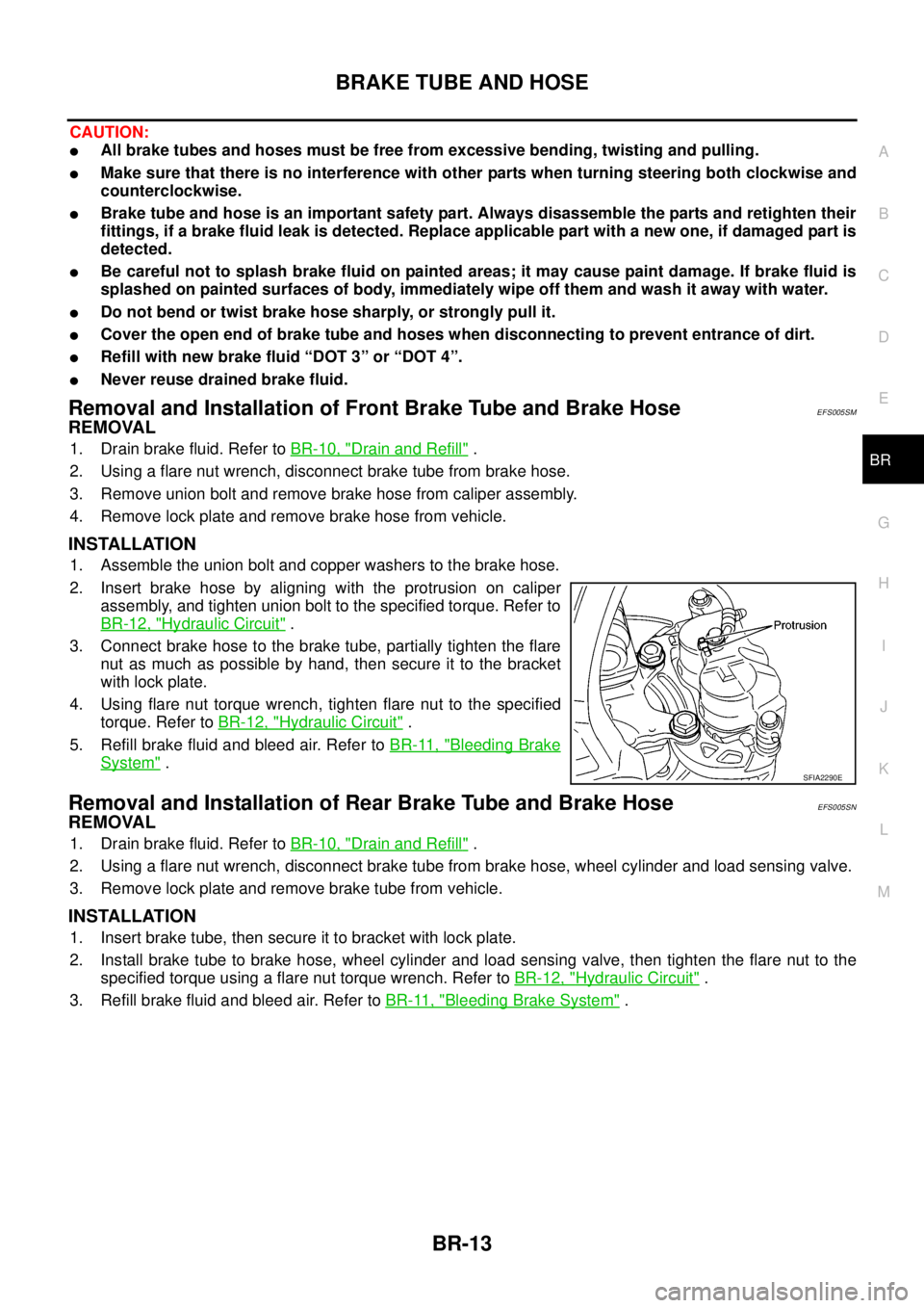
2. Insert brake hose by aligning with the protrusion on caliper
assembly, and tighten union bolt to the specified torque. Refer to
BR-12, "
Hydraulic Circuit".
3. Connect brake hose to the brake tube, partially tighten the flare
nut as much as possible by hand, then secure it to the bracket
with lock plate.
4. Using flare nut torque wrench, tighten flare nut to the specified
torque. Refer toBR-12, "
Hydraulic Circuit".
5. Refill brake fluid and bleed air. Refer toBR-11, "
Bleeding Brake
System".
Removal and Installation of Rear Brake Tube and Brake HoseEFS005SN
REMOVAL
1. Drain brake fluid. Refer toBR-10, "Drain and Refill".
2. Using a flare nut wrench, disconnect brake tube from brake hose, wheel cylinder and load sensing valve.
3. Remove lock plate and remove brake tube from vehicle.
INSTALLATION
1. Insert brake tube, then secure it to bracket with lock plate.
2. Install brake tube to brake hose, wheel cylinder and load sensing valve, then tighten the flare nut to the
specified torque using a flare nut torque wrench. Refer toBR-12, "
Hydraulic Circuit".
3. Refill brake fluid and bleed air. Refer toBR-11, "
Bleeding Brake System".
SFIA2290E
Page 801 of 3171
LOAD SENSING VALVE
BR-15
C
D
E
G
H
I
J
K
L
MA
B
BR
LOAD SENSING VALVEPFP:46400
Removal and InstallationEFS006A7
CAUTION:
lAlways use a flare nut wrench to remove brake tube. Be careful not to damage flare nut and brake
tube. Also, use flare nut torque wrench for brake tube installation and tightening to the specified
torque. Refer toBR-12, "
Hydraulic Circuit".
lRefill with new brake fluid “DOT 3” or “DOT 4”.
lNever reuse drained brake fluid.
REMOVAL
1. Drain brake fluid.
2. Cover brake line connections/openings to protect them from foreign material such as dust or dirt.
3. Using a flare nut wrench, remove flare nut on brake tube from load sensing valve.
4. Remove mounting bolts to remove load sensing valve.
INSTALLATION
lCarefully performing the following, install in the reverse order of removal.
lAfter installing load sensing valve to vehicle, perform the following: bleed air from brake line. Refer toBR-
11 , "Bleeding Brake System", and check mounting length “L” of sensor spring.
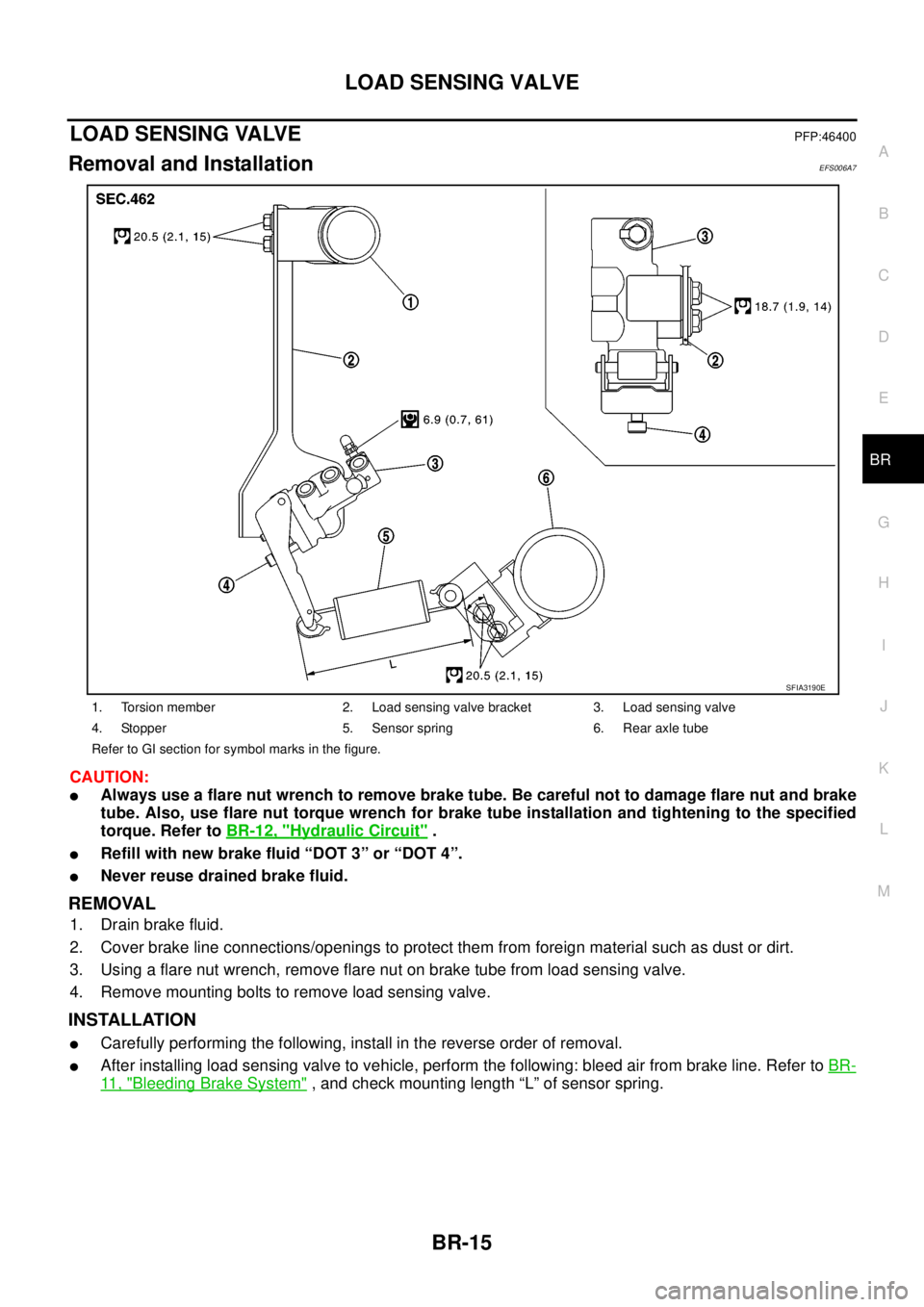
1. Torsion member 2. Load sensing valve bracket 3. Load sensing valve
4. Stopper 5. Sensor spring 6. Rear axle tube
Refer to GI section for symbol marks in the figure.
SFIA3190E
Page 802 of 3171
BR-16
LOAD SENSING VALVE
Inspection
EFS006A8
INSPECTION
1. With the vehicle in unladen condition, a person should sit in driver's seat at the rear. Then he/she should
get out of car gently. (This is to stabilize suspension deflection.)
NOTE:
“Unladen condition”: with full coolant, lubricant, 6 to 8 litters of fuel, spare tyre, jack, and hand tools
loaded.
2. Press load sensing valve against stopper bolt. Check if center-to-center length “L” between adjusting ref-
erence hole and reference pin is as specified below.
lIf measurement is outside the standard, perform following;
loosen mounting bolt of sensor spring bracket. By moving
sensor spring bracket, adjust so that the length “L” comes into
specified range.
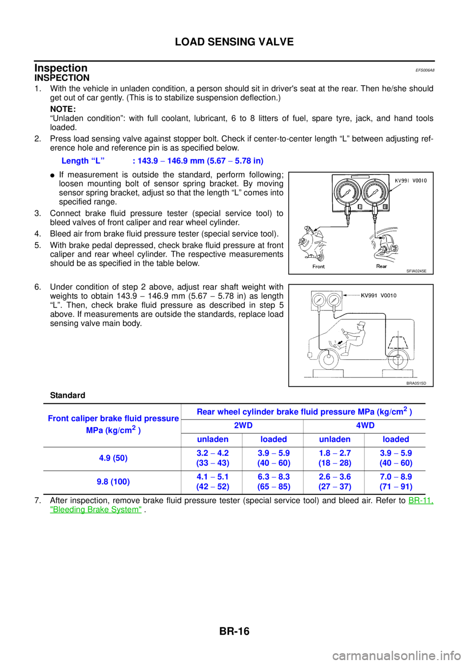
3. Connect brake fluid pressure tester (special service tool) to
bleed valves of front caliper and rear wheel cylinder.
4. Bleed air from brake fluid pressure tester (special service tool).
5. With brake pedal depressed, check brake fluid pressure at front
caliper and rear wheel cylinder. The respective measurements
should be as specified in the table below.
6. Under condition of step 2 above, adjust rear shaft weight with
weights to obtain 143.9-146.9 mm (5.67-5.78 in) as length
“L”. Then, check brake fluid pressure as described in step 5
above. If measurements are outside the standards, replace load
sensing valve main body.
Standard
7. After inspection, remove brake fluid pressure tester (special service tool) and bleed air. Refer toBR-11,
"Bleeding Brake System". Length “L” : 143.9-146.9 mm (5.67-5.78 in)
SFIA0245E
BRA0515D
Front caliper brake fluid pressure
MPa (kg/cm
2)Rear wheel cylinder brake fluid pressure MPa (kg/cm
2)
2WD 4WD
unladen loaded unladen loaded
4.9 (50)3.2-4.2
(33-43)3.9-5.9
(40-60)1.8-2.7
(18-28)3.9-5.9
(40-60)
9.8 (100)4.1-5.1
(42-52)6.3-8.3
(65-85)2.6-3.6
(27-37)7.0-8.9
(71-91)
Page 803 of 3171
BRAKE MASTER CYLINDER
BR-17
C
D
E
G
H
I
J
K
L
MA
B
BR
BRAKE MASTER CYLINDERPFP:46010
On-Board InspectionEFS005SP
LEAK INSPECTION
lCheck for fluid leakage from master cylinder attachment portion such as reservoir tank and brake tube
connections.
Removal and InstallationEFS005SQ
CAUTION:
Be careful not to splash brake fluid on painted areas; it may cause paint damage. If brake fluid is
splashed on painted areas immediately wipe off then and wash it away with water.
REMOVAL
1. Drain brake fluid. Refer toBR-10, "Drain and Refill".
2. Using flare nut wrench, disconnect brake tube from master cylinder assembly.
3. Remove master cylinder assembly mounting nuts and master cylinder assembly.
INSTALLATION
lInstallation is in the reverse order of the removal.
lRefill brake fluid and bleed air. Refer toBR-11, "Bleeding Brake System".
CAUTION:
lRefill with new brake fluid “DOT 3” or “DOT 4”.
lNever reuse drained brake fluid.
ComponentsEFS005SR
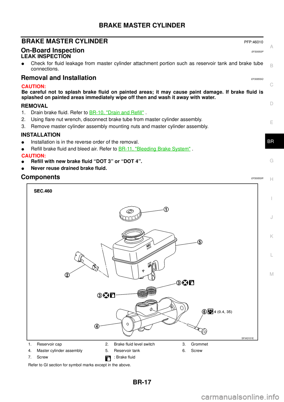
1. Reservoir cap 2. Brake fluid level switch 3. Grommet
4. Master cylinder assembly 5. Reservoir tank 6. Screw
7. Screw : Brake fluid
Refer to GI section for symbol marks except in the above.
SFIA3101E
Page 807 of 3171
BRAKE BOOSTER
BR-21
C
D
E
G
H
I
J
K
L
MA
B
BR
INSTALLATION
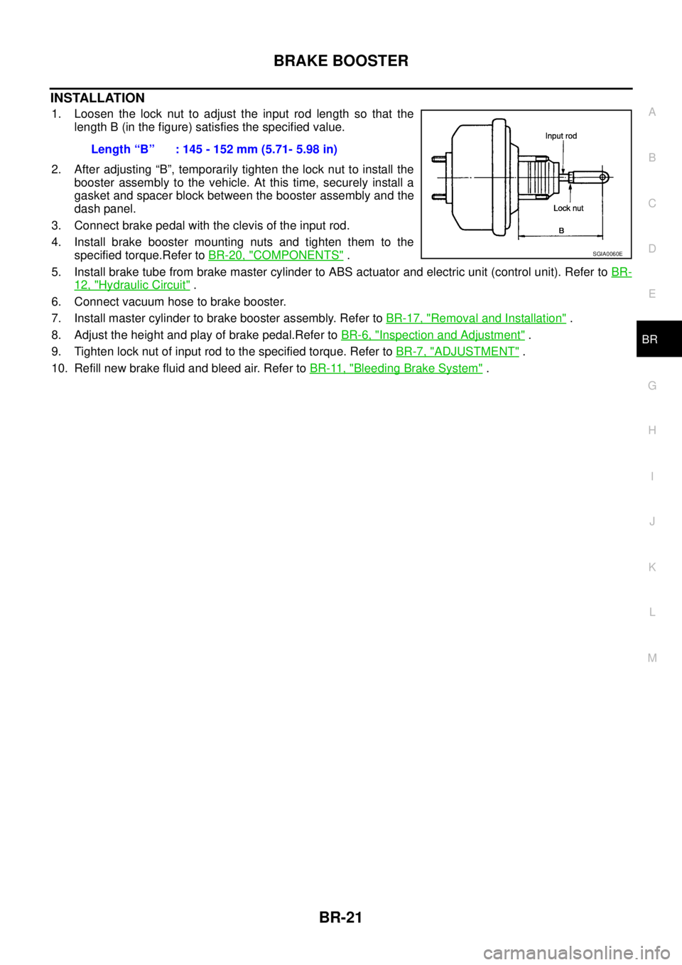
1. Loosen the lock nut to adjust the input rod length so that the
length B (in the figure) satisfies the specified value.
2. After adjusting “B”, temporarily tighten the lock nut to install the
booster assembly to the vehicle. At this time, securely install a
gasket and spacer block between the booster assembly and the
dash panel.
3. Connect brake pedal with the clevis of the input rod.
4. Install brake booster mounting nuts and tighten them to the
specified torque.Refer toBR-20, "
COMPONENTS".
5. Install brake tube from brake master cylinder to ABS actuator and electric unit (control unit). Refer toBR-
12, "Hydraulic Circuit".
6. Connect vacuum hose to brake booster.
7. Install master cylinder to brake booster assembly. Refer toBR-17, "
Removal and Installation".
8. Adjust the height and play of brake pedal.Refer toBR-6, "
Inspection and Adjustment".
9. Tighten lock nut of input rod to the specified torque. Refer toBR-7, "
ADJUSTMENT".
10. Refill new brake fluid and bleed air. Refer toBR-11, "
Bleeding Brake System". Length“B” :145-152mm(5.71-5.98in)
SGIA0060E
Page 812 of 3171
BR-26
FRONT DISC BRAKE
Removal and Installation of Brake Caliper Assembly
EFS005T1
REMOVAL
1. Remove tyre from vehicle.
2. Fasten disc rotor using wheel nut.
CAUTION:
Align the matching marks of disc rotor and wheel hub, which were marked at the time of removal
when reusing disc rotor.
3. Drain brake fluid. Refer toBR-10, "
Drain and Refill".
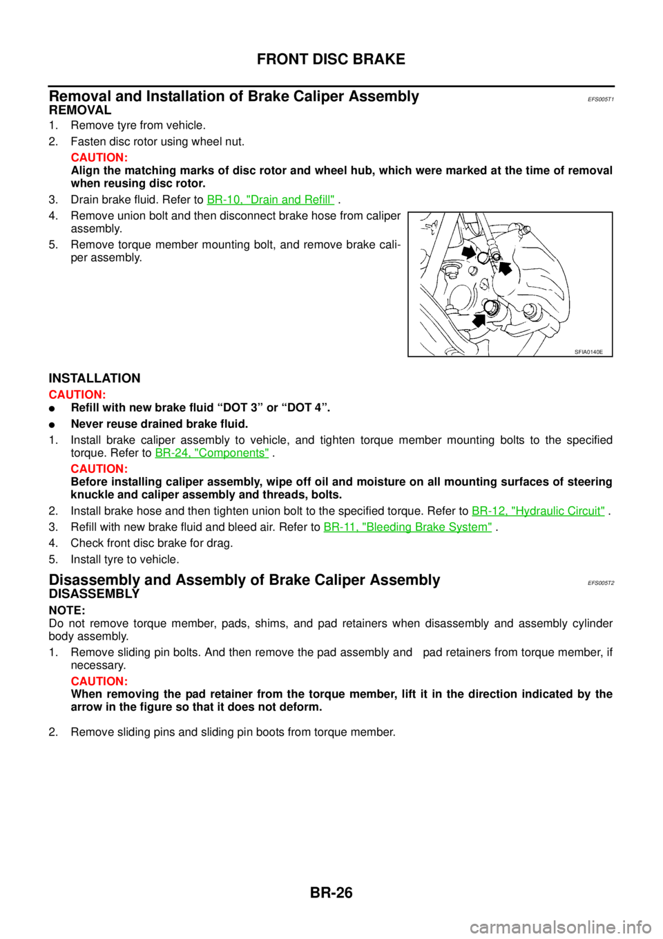
4. Remove union bolt and then disconnect brake hose from caliper
assembly.
5. Remove torque member mounting bolt, and remove brake cali-
per assembly.
INSTALLATION
CAUTION:
lRefill with new brake fluid “DOT 3” or “DOT 4”.
lNever reuse drained brake fluid.
1. Install brake caliper assembly to vehicle, and tighten torque member mounting bolts to the specified
torque. Refer toBR-24, "
Components".
CAUTION:
Before installing caliper assembly, wipe off oil and moisture on all mounting surfaces of steering
knuckle and caliper assembly and threads, bolts.
2. Install brake hose and then tighten union bolt to the specified torque. Refer toBR-12, "
Hydraulic Circuit".
3. Refill with new brake fluid and bleed air. Refer toBR-11, "
Bleeding Brake System".
4. Check front disc brake for drag.
5. Install tyre to vehicle.
Disassembly and Assembly of Brake Caliper AssemblyEFS005T2
DISASSEMBLY
NOTE:
Do not remove torque member, pads, shims, and pad retainers when disassembly and assembly cylinder
body assembly.
1. Remove sliding pin bolts. And then remove the pad assembly and pad retainers from torque member, if
necessary.
CAUTION:
When removing the pad retainer from the torque member, lift it in the direction indicated by the
arrow in the figure so that it does not deform.
2. Remove sliding pins and sliding pin boots from torque member.
SFIA0140E
Page 820 of 3171
BR-34
REAR DRUM BRAKE
Removal and Installation of Wheel Cylinder
EFS006AH
REMOVAL
1. Drain brake fluid. Refer toBR-10, "Drain and Refill".
2. Remove rear brake shoe assembly.
3. Remove brake tube from the wheel cylinder.
4. Remove bolts on the wheel cylinder, and then remove wheel cylinder from the back plate.
INSTALLATION
lInstallation is the reverse order of removal. Tighten bolts to the specified torque. Refer toBR-30, "Compo-
nents".
lRefill with new brake fluid and bleed air. Refer toBR-11, "Bleeding Brake System".
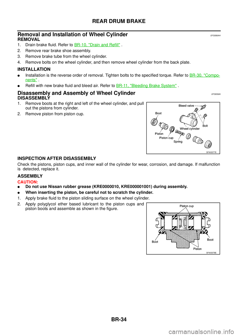
Disassembly and Assembly of Wheel CylinderEFS006AI
DISASSEMBLY
1. Remove boots at the right and left of the wheel cylinder, and pull
out the pistons from cylinder.
2. Remove piston from piston cup.
INSPECTION AFTER DISASSEMBLY
Check the pistons, piston cups, and inner wall of the cylinder for wear, corrosion, and damage. If malfunction
is detected, replace it.
ASSEMBLY
CAUTION:
lDo not use Nissan rubber grease (KRE0000010, KRE000001001) during assembly.
lWhen inserting the piston, be careful not to scratch the cylinder.
1. Apply brake fluid to the piston sliding surface on the wheel cylinder.
2. Apply polyglycol ether based lubricant to the piston cups and
piston boots and assemble as shown in the figure.
SFIA3077E
SFIA3078E