coolant capacity NISSAN NAVARA 2005 Repair Workshop Manual
[x] Cancel search | Manufacturer: NISSAN, Model Year: 2005, Model line: NAVARA, Model: NISSAN NAVARA 2005Pages: 3171, PDF Size: 49.59 MB
Page 885 of 3171

CO-1
ENGINE COOLING SYSTEM
B ENGINE
CONTENTS
C
D
E
F
G
H
I
J
K
L
M
SECTIONCO
A
CO
ENGINE COOLING SYSTEM
PRECAUTIONS .......................................................... 2
Precautions For Liquid Gasket ................................. 2
LIQUID GASKET APPLICATION PROCEDURE..... 2
PREPARATION ........................................................... 3
Special Service Tools ............................................... 3
Commercial Service Tools ........................................ 3
OVERHEATING CAUSE ANALYSIS .......................... 4
Troubleshooting Chart .............................................. 4
COOLING SYSTEM .................................................... 6
Cooling Circuit .......................................................... 6
ENGINE COOLANT .................................................... 7
Inspection ................................................................. 7
LEVEL CHECK ..................................................... 7
CHECKING RADIATOR SYSTEM FOR LEAKS..... 7
Changing Engine Coolant ........................................ 7
DRAINING ENGINE COOLANT ........................... 8
REFILLING ENGINE COOLANT .......................... 8
FLUSHING COOLING SYSTEM ........................... 9
RADIATOR .................................................................11
Components ............................................................ 11
Removal and Installation ......................................... 11
REMOVAL ............................................................ 11
INSPECTION AFTER REMOVAL ....................... 13
INSTALLATION ................................................... 14
INSPECTION AFTER INSTALLATION ............... 14
RADIATOR (ALUMINUM TYPE) .............................. 15
Components ........................................................... 15
Disassembly and Assembly ................................... 15
PREPARATION ................................................... 15
DISASSEMBLY ................................................... 15
ASSEMBLY ......................................................... 16
INSPECTION ...................................................... 18COOLING FAN .......................................................... 19
Components (Crankshaft Driven Type) .................. 19
Removal and Installation ........................................ 19
REMOVAL ........................................................... 19
INSPECTION AFTER REMOVAL ....................... 19
INSTALLATION ................................................... 19
Removal and Installation (Motor Driven Type) (Mod-
els with A/C) ........................................................... 19
REMOVAL ........................................................... 19
INSTALLATION ................................................... 20
WATER PUMP .......................................................... 21
Components ........................................................... 21
Removal and Installation ........................................ 21
REMOVAL ........................................................... 21
INSPECTION AFTER REMOVAL ....................... 22
INSTALLATION ................................................... 22
INSPECTION AFTER INSTALLATION ................ 22
THERMOSTAT AND WATER PIPING ...................... 23
Components ........................................................... 23
Removal and Installation ........................................ 24
REMOVAL ........................................................... 24
INSPECTION AFTER REMOVAL ....................... 24
INSTALLATION ................................................... 24
INSPECTION AFTER INSTALLATION ................ 25
SERVICE DATA AND SPECIFICATIONS (SDS) ...... 26
Standard and Limit .................................................. 26
ENGINE COOLANT CAPACITY .......................... 26
THERMOSTAT .................................................... 26
RESERVOIR TANK ............................................. 26
Page 893 of 3171

ENGINE COOLANT
CO-9
C
D
E
F
G
H
I
J
K
L
MA
CO
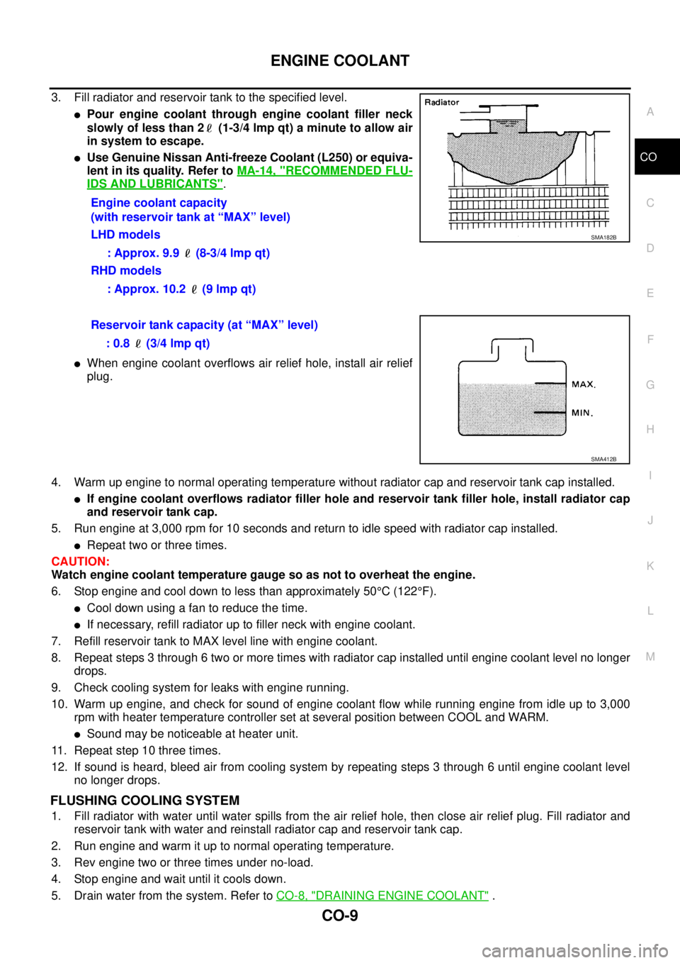
3. Fill radiator and reservoir tank to the specified level.
lPour engine coolant through engine coolant filler neck
slowly of less than 2 (1-3/4 lmp qt) a minute to allow air
in system to escape.
lUse Genuine Nissan Anti-freeze Coolant (L250) or equiva-
lent in its quality. Refer toMA-14, "
RECOMMENDED FLU-
IDS AND LUBRICANTS".
lWhen engine coolant overflows air relief hole, install air relief
plug.
4. Warm up engine to normal operating temperature without radiator cap and reservoir tank cap installed.
lIf engine coolant overflows radiator filler hole and reservoir tank filler hole, install radiator cap
and reservoir tank cap.
5. Run engine at 3,000 rpm for 10 seconds and return to idle speed with radiator cap installed.
lRepeat two or three times.
CAUTION:
Watch engine coolant temperature gauge so as not to overheat the engine.
6. Stop engine and cool down to less than approximately 50°C(122°F).
lCool down using a fan to reduce the time.
lIf necessary, refill radiator up to filler neck with engine coolant.
7. Refill reservoir tank to MAX level line with engine coolant.
8. Repeat steps 3 through 6 two or more times with radiator cap installed until engine coolant level no longer
drops.
9. Check cooling system for leaks with engine running.
10. Warm up engine, and check for sound of engine coolant flow while running engine from idle up to 3,000
rpm with heater temperature controller set at several position between COOL and WARM.
lSound may be noticeable at heater unit.
11. Repeat step 10 three times.
12. If sound is heard, bleed air from cooling system by repeating steps 3 through 6 until engine coolant level
no longer drops.
FLUSHING COOLING SYSTEM
1. Fill radiator with water until water spills from the air relief hole, then close air relief plug. Fill radiator and
reservoir tank with water and reinstall radiator cap and reservoir tank cap.
2. Run engine and warm it up to normal operating temperature.
3. Rev engine two or three times under no-load.
4. Stop engine and wait until it cools down.
5. Drain water from the system. Refer toCO-8, "
DRAINING ENGINE COOLANT". Engine coolant capacity
(with reservoir tank at “MAX” level)
LHD models
: Approx. 9.9 (8-3/4 lmp qt)
RHD models
: Approx. 10.2 (9 lmp qt)
SMA182B
Reservoir tank capacity (at “MAX” level)
: 0.8 (3/4 lmp qt)
SMA412B
Page 910 of 3171

CO-26
SERVICE DATA AND SPECIFICATIONS (SDS)
SERVICE DATA AND SPECIFICATIONS (SDS)
PFP:00030
Standard and LimitEBS01E6Y
ENGINE COOLANT CAPACITY
Unit: (lmp qt)
THERMOSTAT
RESERVOIR TANK
Unit:kPa(bar,kg/cm2, psi)
Engine coolant capacity
(With reservoir tank at “MAX” level)LHD models Approx. 9.9 (8-3/4)
RHD models Approx. 10.2 (9)
Reservoir tank (at “MAX” level)0.8 (3/4)
Valve opening temperature 80.5 - 83.5°C (177 - 182°F)
Full open lift amount More than 9 mm/ 95°C (0.35 in/203°F)
Valve closing temperature More than 77°C(171°F)
Cap relief pressureStandard 98.2 - 117.8 (0.98 - 1.18, 1.0 - 1.2, 14 - 17)
Limit 59 (0.59, 0.6, 9)
Leakage test pressure 157 (1.57, 1.6, 23)
Page 2277 of 3171

MA-2
Checking Rear Final Drive Oil (Rear Differential
Gear Oil) ................................................................. 33
OIL LEAKAGE AND OIL LEVEL ......................... 33
Changing Rear Final Drive Oil (Rear Differential
Gear Oil) ................................................................. 34
DRAINING ........................................................... 34
FILLING ............................................................... 34
Balancing Wheels ................................................... 34
Tire Rotation ........................................................... 34
Checking Brake Fluid Level and Leaks .................. 35
Checking Brake Lines and Cables ......................... 35
Changing Brake Fluid ............................................. 35
Checking Disc Brake .............................................. 35
ROTOR ................................................................ 35
CALIPER ............................................................. 36
PAD ..................................................................... 36
Checking Drum Brake ............................................ 36
DRUM .................................................................. 36
WHEEL CYLINDER ............................................. 36
LINING ................................................................. 37
Checking Steering Gear and Linkage ..................... 37
STEERING GEAR ............................................... 37
STEERING LINKAGE .......................................... 37
Checking Power Steering Fluid and Lines .............. 37CHECKING FLUID LEVEL .................................. 37
CHECKING LINES ............................................... 37
Checking Axle and Suspension Parts ..................... 38
FRONT AND REAR AXLE AND SUSPENSION
PARTS ................................................................. 38
FRONT DRIVE SHAFT ........................................ 38
Lubricating Locks, Hinges and Hood Latches ......... 39
Checking Seat Belts, Buckles, Retractors, Anchors
and Adjusters .......................................................... 40
Checking Body Corrosion ....................................... 40
HEMMED PANELS .............................................. 40
PANEL JOINT ...................................................... 40
PANEL EDGE ...................................................... 40
PARTS CONTACT ............................................... 40
PROTECTORS .................................................... 40
ANTI-CORROSION MATERIALS ........................ 40
DRAIN HOLES ..................................................... 40
SERVICE DATA AND SPECIFICATIONS (SDS) ...... 41
Standard and Limit .................................................. 41
BELT DEFLECTION ............................................ 41
RESERVOIR TANK ............................................. 41
ENGINE COOLANT CAPACITY (APPROXI-
MATE) .................................................................. 41
ENGINE OIL CAPACITY (APPROXIMATE) ........ 41
Page 2289 of 3171

MA-14
RECOMMENDED FLUIDS AND LUBRICANTS
RECOMMENDED FLUIDS AND LUBRICANTS
PFP:00000
Fluids and LubricantsELS001JA
*1: For further details, see “SAE Viscosity Number”.
*2: Never use API CG-4.
*3: Use Genuine NISSAN Anti-freeze Coolant (L250) or equivalent in its quality, in order to avoid possible aluminum corrosion within the
engine cooling system caused by the use of non-genuine engine coolant.
Note that any repairs for the incidents within the engine cooling system while using non-genuine engine coolant may not be
covered by the warranty even if such incidents occurred during the warranty period.
*4: Contact a Nissan dealership for more information regarding suitable fluids, including recommended brand(s) of DEXRON
™III/MER-
CON™ Automatic Transmission Fluid.
*5:Using automatic transmission fluid other than Genuine NISSAN ATF Matic Fluid J will cause deterioration in driveability
and automatic transmission durability, and may damage the automatic transmission, which is not covered by the warranty.
*6: DEXRON™III type ATF can be used.
*7: Never mix different types of fluids (DOT 3 and DOT 4).Capacity (Approximate)
Recommended Fluids/Lubricants
Liter Imp measure
Engine oil
Drain and refillWith oil filter change 7.6 6-5/8 qt
lDiesel engine
API CF-4*1, *2
ACEA B1, B3, B4, B5*1 Without oil filter change 7.1 6-1/4 qt
Dry engine (engine overhaul) 7.9 7 qt
Cooling sys-
tem (with res-
ervoir)LHD models 9.9 8-3/4 qt
lGenuine NISSAN Anti-freeze Coolant (L250) or
equivalent in its quality*3 RHD models 10.2 9 qt
Reservoir tank 0.8 3/4 qt
Manual transmission gear oil2WD 3.99 7 pt
lGenuine NISSAN gear oil or API GL-4, Viscosity
SAE 75W-85 or 75W-90
4WD 4.32 7-5/8 pt
Transfer fluid 2.0 1-3/4 qt
lGenuine NISSAN ATF or equivalent*4
Differential gear oilFront 0.85 1-1/2 pt
lStandard differential gear:
Gear Oil Hypoid LSD (Part No.: KLD31-8090403)
or API GL-5, Viscosity SAE 80W-90*1
lLimited-slip differential (LSD) gear:
Gear Oil Hypoid LSD (Part No. KLD31-8090403)
or equivalent Rear 2.01 3-1/2 pt
Automatic transmission fluid 10.3 9-1/8 qt Genuine NISSAN ATF Matic Fluid J*5
Power steering fluid — — Genuine NISSAN PSF or equivalent*6
Brake and clutch fluid — —
lDOT 3 or DOT 4 (US FMVSS No. 116)*7
Multi-purpose grease — — NLGI No. 2 (Lithium soap base)
Page 2295 of 3171

MA-20
ENGINE MAINTENANCE
REFILLING ENGINE COOLANT
1. Install reservoir tank, and radiator drain plug.
CAUTION:
Be sure to clean radiator drain plug and install with new O-ring.
lIf water drain plug on cylinder block is removed, close and tighten it. Refer toEM-110, "CYLIN-
DER BLOCK".
2. Make sure that each hose clamp has been firmly tightened.
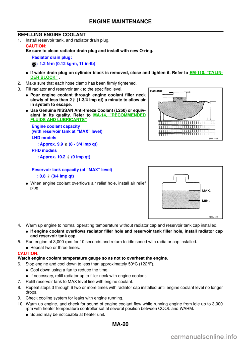
3. Fill radiator and reservoir tank to the specified level.
lPour engine coolant through engine coolant filler neck
slowly of less than 2 (1-3/4 lmp qt) a minute to allow air
in system to escape.
lUse Genuine NISSAN Anti-freeze Coolant (L250) or equiv-
alent in its quality. Refer toMA-14, "
RECOMMENDED
FLUIDS AND LUBRICANTS"
lWhen engine coolant overflows air relief hole, install air relief
plug.
4. Warm up engine to normal operating temperature without radiator cap and reservoir tank cap installed.
lIf engine coolant overflows radiator filler hole and reservoir tank filler hole, install radiator cap
and reservoir tank cap.
5. Run engine at 3,000 rpm for 10 seconds and return to idle speed with radiator cap installed.
lRepeat two or three times.
CAUTION:
Watch engine coolant temperature gauge so as not to overheat the engine.
6. Stop engine and cool down to less than approximately 50°C(122°F).
lCool down using a fan to reduce the time.
lIf necessary, refill radiator up to filler neck with engine coolant.
7. Refill reservoir tank to MAX level line with engine coolant.
8. Repeat steps 3 through 6 two or more times with radiator cap installed until engine coolant level no longer
drops.
9. Check cooling system for leaks with engine running.
10. Warm up engine, and check for sound of engine coolant flow while running engine from idle up to 3,000
rpm with heater temperature controller set at several position between COOL and WARM.
lSound may be noticeable at heater unit.Radiator drain plug:
: 1.2 N·m (0.12 kg-m, 11 in-lb)
Engine coolant capacity
(with reservoir tank at “MAX” level)
LHD models
: Approx. 9.9 (8 - 3/4 lmp qt)
RHD models
: Approx. 10.2 (9 lmp qt)
SMA182B
Reservoir tank capacity (at “MAX” level)
: 0.8 (3/4 lmp qt)
SMA412B
Page 2316 of 3171

SERVICE DATA AND SPECIFICATIONS (SDS)
MA-41
C
D
E
F
G
H
I
J
K
MA
B
MA
SERVICE DATA AND SPECIFICATIONS (SDS)PFP:00030
Standard and LimitELS001J8
BELT DEFLECTION
*: When engine is cold.
RESERVOIR TANK
Unit:kPa(bar,kg/cm2, psi)
ENGINE COOLANT CAPACITY (APPROXIMATE)
Unit: (lmp qt)
ENGINE OIL CAPACITY (APPROXIMATE)
Unit: (lmp qt) Applied beltBelt deflection with 98 N (10 kg, 22 lb) force applied* mm (in)
New Adjusted Limit for re-adjusting
A/C compressor, alternator and water
pump belt2.9 - 3.4 (0.114 - 0.134) 3.9 - 4.4 (0.154 - 0.173) 8.5 (0.335)
Power steering oil pump belt 4.6 - 5.4 (0.181 - 0.213) 7.1 - 7.7 (0.280 - 0.303) 11.3 (0.445)
Cap relief pressureStandard 98.2 - 117.8 (0.98 - 1.18, 1.0 - 1.2, 14 - 17)
Limit 59 (0.59, 0.6, 9)
Leakage test pressure 157 (1.57, 1.6, 23)
Engine coolant capacity (With reser-
voir tank at “MAX” level)LHD models 9.9 (8-3/4)
RHD models 10.2 (9)
Reservoir tank coolant capacity (At “MAX” level) 0.8 (3/4)
Drain and refillWith oil filter change 7.6 (6-5/8)
Without oil filter change 7.1 (6-1/4)
Dry engine (Overhaul)7.9 (7)