fuel tank removal NISSAN NAVARA 2005 Repair Workshop Manual
[x] Cancel search | Manufacturer: NISSAN, Model Year: 2005, Model line: NAVARA, Model: NISSAN NAVARA 2005Pages: 3171, PDF Size: 49.59 MB
Page 908 of 3171
CO-24
THERMOSTAT AND WATER PIPING
Removal and Installation
EBS01E6X
WARNING:
Do not remove radiator cap and/or reservoir tank cap when engine is hot. Serious burns could occur
from high pressure engine coolant escaping from radiator and/or reservoir tank.
REMOVAL
1. Remove front engine undercover and middle engine undercover. Refer toEI-15, "FRONT BUMPER".
2. Drain engine coolant from radiator drain plug at the bottom of radiator, and from water drain plug at the
side of cylinder block. Refer toCO-7, "
Changing Engine Coolant"andEM-110, "CYLINDER BLOCK".
CAUTION:
Perform this step when engine is cold.
3. Remove engine cover. Refer toEM-20, "
INTAKE MANIFOLD".
4. Disconnect radiator hoses (upper and lower) from engine side. Refer toCO-11, "
RADIATOR".
5. Remove air inlet pipe and air duct between air cleaner case and turbocharger. Refer toEM-15, "
AIR
CLEANER AND AIR DUCT"andEM-28, "TURBO CHARGER".
6. Remove water outlet, water inlet and thermostat.
7. Remove thermostat housing.
8. Disconnect heater return hose and water hoses at heater return pipe side, and remove heater return pipe.
9. Remove oil level gauge guide mounting bolt, vacuum hoses (to turbocharger boost control solenoid valve)
and spill hose. Refer toEM-36, "
OIL PAN AND OIL STRAINER",EM-20, "INTAKE MANIFOLD"andEM-
44, "INJECTION TUBE AND FUEL INJECTOR".
10. Disconnect water hoses (to EGR cooler) (A/T models), vacuum hoses and heater feed hose at heater
feed pipe side, and remove heater feed pipe. Refer toEM-20, "
INTAKE MANIFOLD".
INSPECTION AFTER REMOVAL
Thermostat
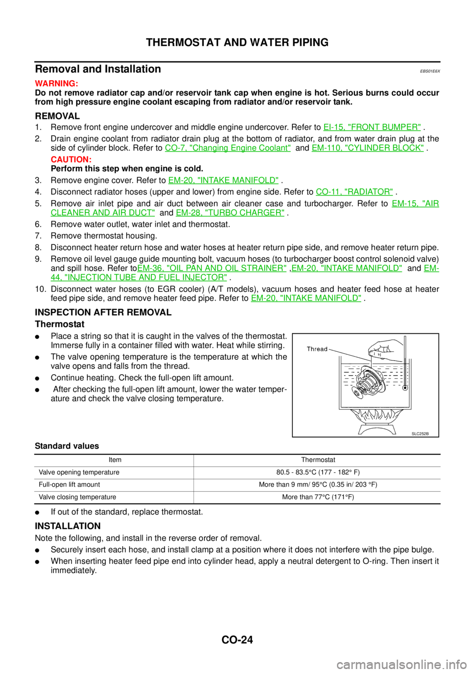
lPlace a string so that it is caught in the valves of the thermostat.
Immerse fully in a container filled with water. Heat while stirring.
lThe valve opening temperature is the temperature at which the
valve opens and falls from the thread.
lContinue heating. Check the full-open lift amount.
lAfter checking the full-open lift amount, lower the water temper-
ature and check the valve closing temperature.
Standard values
lIf out of the standard, replace thermostat.
INSTALLATION
Note the following, and install in the reverse order of removal.
lSecurely insert each hose, and install clamp at a position where it does not interfere with the pipe bulge.
lWhen inserting heater feed pipe end into cylinder head, apply a neutral detergent to O-ring. Then insert it
immediately.
SLC252B
Item Thermostat
Valve opening temperature 80.5 - 83.5°C (177 - 182°F)
Full-open lift amount More than 9 mm/ 95°C (0.35 in/ 203°F)
Valve closing temperature More than 77°C(171°F)
Page 1426 of 3171
EM-44
INJECTION TUBE AND FUEL INJECTOR
INJECTION TUBE AND FUEL INJECTOR
PFP:00018
ComponentsEBS01EK6
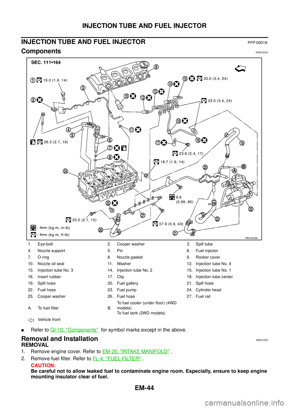
lRefer toGI-10, "Components"for symbol marks except in the above.
Removal and InstallationEBS01E63
REMOVAL
1. Remove engine cover. Refer toEM-20, "INTAKE MANIFOLD".
2. Remove fuel filter. Refer toFL-4, "
FUEL FILTER".
CAUTION:
Be careful not to allow leaked fuel to contaminate engine room. Especially, ensure to keep engine
mounting insulator clear of fuel.
1. Eye-bolt 2. Cooper washer 3. Spill tube
4. Nozzle support 5. Pin 6. Fuel injector
7. O-ring 8. Nozzle gasket 9. Rocker cover
10. Nozzle oil seal 11. Washer 12. Injection tube No. 4
13. Injection tube No. 3 14. Injection tube No. 2 15. Injection tube No. 1
16. Insert rubber 17. Clip 18. Injection tube center
19. Spill hose 20. Fuel gallery 21. Spill hose
22. Fuel hose 23. Fuel pump 24. Cylinder head
25. Cooper washer 26. Fuel hose 27. Fuel rail
A. To fuel filter B.To fuel cooler (under floor) (4WD
models)
To fuel tank (2WD models)
Vehicle front
PBIC4046E
Page 1474 of 3171
EM-92
CYLINDER HEAD
CYLINDER HEAD
PFP:11041
On-Vehicle ServiceEBS01E6A
CHECKING COMPRESSION PRESSURE
1. Warm up engine thoroughly. Then, stop it.
2. Using CONSULT-II, make sure no error codes are indicated for self-diagnosis items. Refer toEC-38,
"Basic Inspection".
lDo not disconnect CONSULT-II until the end of this operation; it will be used to check engine rpm and
for error detection at the end of this operation.
3. Disconnect the battery cable from the negative terminal.
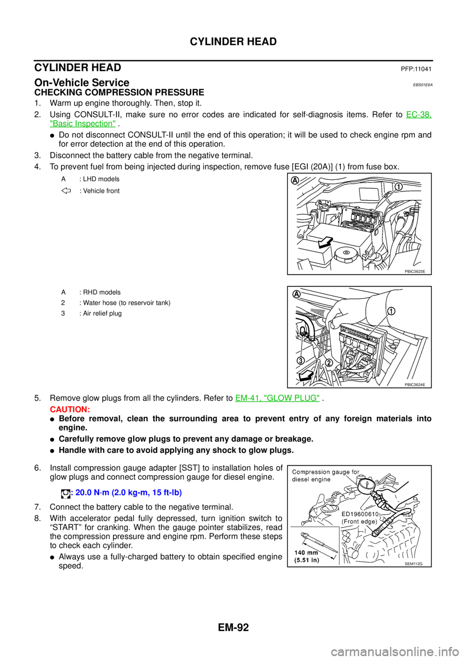
4. To prevent fuel from being injected during inspection, remove fuse [EGI (20A)] (1) from fuse box.
5. Remove glow plugs from all the cylinders. Refer toEM-41, "
GLOW PLUG".
CAUTION:
lBefore removal, clean the surrounding area to prevent entry of any foreign materials into
engine.
lCarefully remove glow plugs to prevent any damage or breakage.
lHandle with care to avoid applying any shock to glow plugs.
6. Install compression gauge adapter [SST] to installation holes of
glow plugs and connect compression gauge for diesel engine.
7. Connect the battery cable to the negative terminal.
8. With accelerator pedal fully depressed, turn ignition switch to
“START” for cranking. When the gauge pointer stabilizes, read
the compression pressure and engine rpm. Perform these steps
to check each cylinder.
lAlways use a fully-charged battery to obtain specified engine
speed.
A : LHD models
: Vehicle front
PBIC3623E
A : RHD models
2 : Water hose (to reservoir tank)
3:Airreliefplug
PBIC3624E
: 20.0 N·m (2.0 kg-m, 15 ft-lb)
SEM112G
Page 1585 of 3171
FL-1
FUEL SYSTEM
B ENGINE
CONTENTS
C
D
E
F
G
H
I
J
K
L
M
SECTIONFL
A
FL
FUEL SYSTEM
PREPARATION ........................................................... 2
Commercial Service Tools ........................................ 2
FUEL SYSTEM ........................................................... 3
Checking Fuel Lines ................................................. 3
General Precautions ................................................ 3
FUEL FILTER .............................................................. 4
Components ............................................................. 4
Removal and Installation .......................................... 4
REMOVAL ............................................................. 4
INSTALLATION ..................................................... 5
INSPECTION AFTER INSTALLATION ................. 5
Air Bleeding .............................................................. 5
Draining Water from Fuel Filter ................................ 6
FUEL COOLER .......................................................... 7
Components (4WD Models Only) ............................ 7
Removal and Installation (4WD Models Only) ......... 7
REMOVAL ............................................................. 7
INSTALLATION ..................................................... 8
INSPECTION AFTER INSTALLATION ................. 8FUEL TANK ................................................................ 9
Components ............................................................. 9
Removal and Installation .......................................... 9
REMOVAL ............................................................. 9
INSTALLATION ................................................... 12
INSPECTION AFTER INSTALLATION ................ 13
FUEL LEVEL SENSOR UNIT ................................... 14
Components ........................................................... 14
Removal and Installation ........................................ 14
REMOVAL ........................................................... 14
INSPECTION AFTER REMOVAL ....................... 14
INSTALLATION ................................................... 15
INSPECTION AFTER INSTALLATION ................ 15
SERVICE DATA AND SPECIFICATIONS (SDS) ...... 16
Standard and Limit .................................................. 16
Page 1591 of 3171
FUEL COOLER
FL-7
C
D
E
F
G
H
I
J
K
L
MA
FL
FUEL COOLERPFP:17511
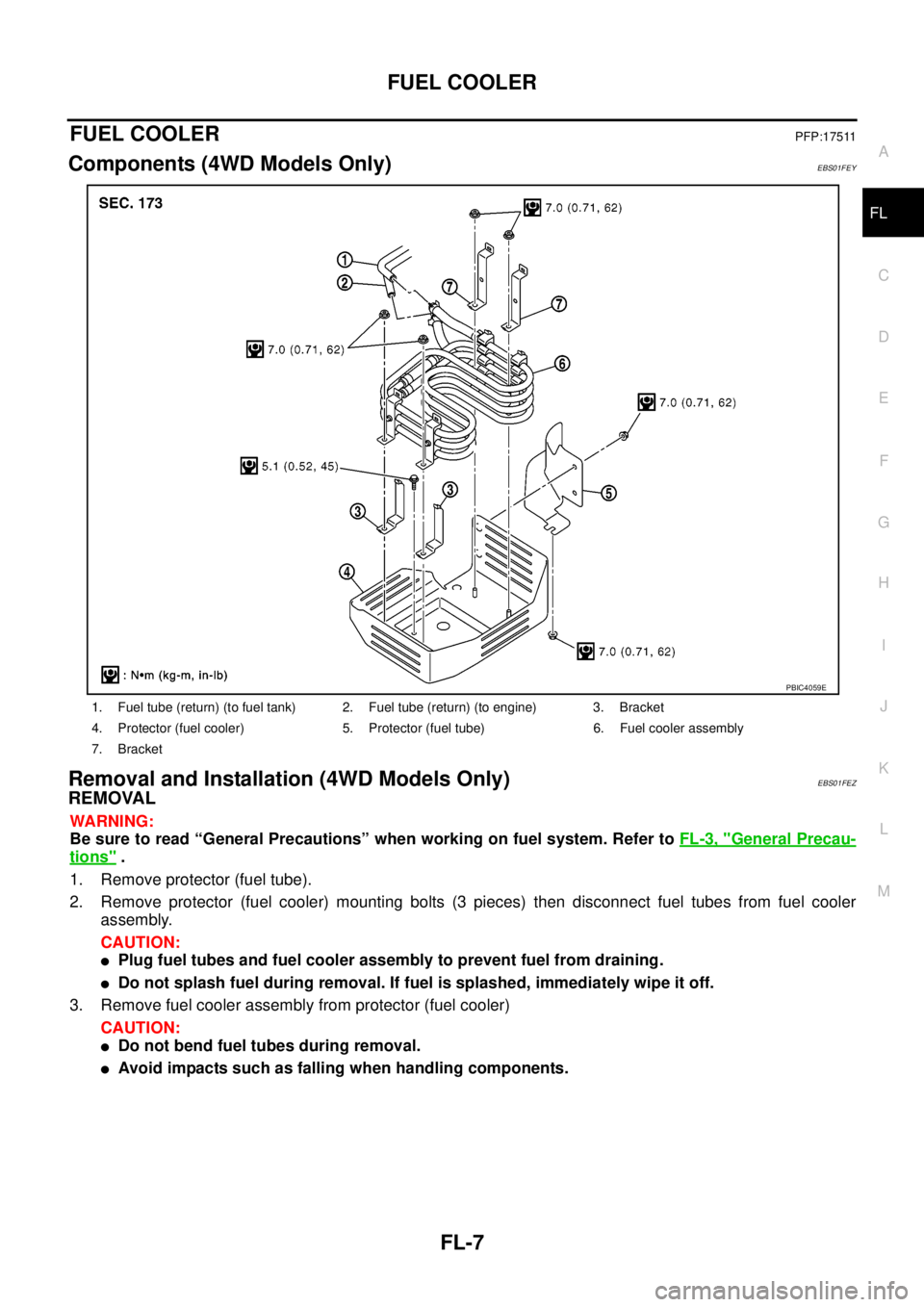
Components (4WD Models Only)EBS01FEY
Removal and Installation (4WD Models Only)EBS01FEZ
REMOVAL
WARNING:
Be sure to read “General Precautions” when working on fuel system. Refer toFL-3, "
General Precau-
tions".
1. Remove protector (fuel tube).
2. Remove protector (fuel cooler) mounting bolts (3 pieces) then disconnect fuel tubes from fuel cooler
assembly.
CAUTION:
lPlug fuel tubes and fuel cooler assembly to prevent fuel from draining.
lDo not splash fuel during removal. If fuel is splashed, immediately wipe it off.
3. Remove fuel cooler assembly from protector (fuel cooler)
CAUTION:
lDo not bend fuel tubes during removal.
lAvoid impacts such as falling when handling components.
1. Fuel tube (return) (to fuel tank) 2. Fuel tube (return) (to engine) 3. Bracket
4. Protector (fuel cooler) 5. Protector (fuel tube) 6. Fuel cooler assembly
7. Bracket
PBIC4059E
Page 1593 of 3171
FUEL TANK
FL-9
C
D
E
F
G
H
I
J
K
L
MA
FL
FUEL TANKPFP:17202
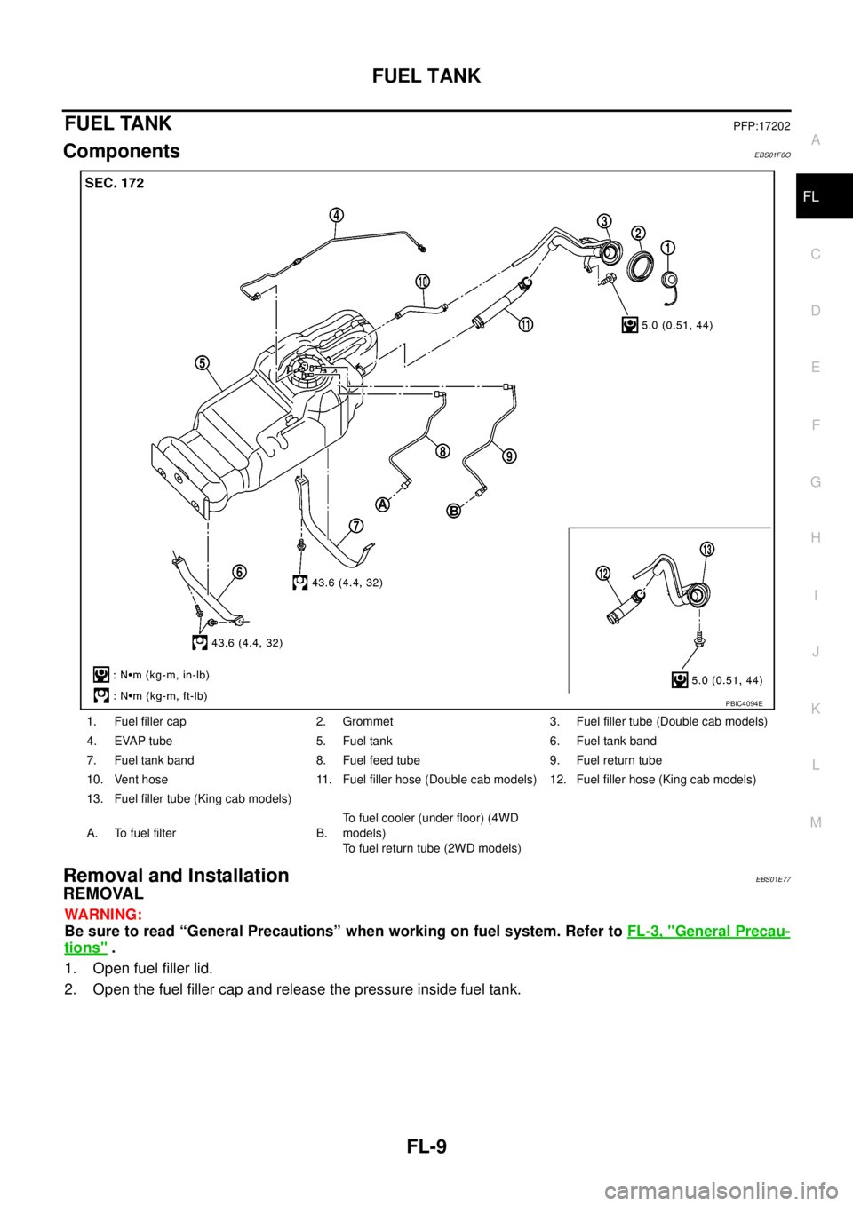
ComponentsEBS01F6O
Removal and InstallationEBS01E77
REMOVAL
WARNING:
Be sure to read “General Precautions” when working on fuel system. Refer toFL-3, "
General Precau-
tions".
1. Open fuel filler lid.
2. Open the fuel filler cap and release the pressure inside fuel tank.
1. Fuel filler cap 2. Grommet 3. Fuel filler tube (Double cab models)
4. EVAP tube 5. Fuel tank 6. Fuel tank band
7. Fuel tank band 8. Fuel feed tube 9. Fuel return tube
10. Vent hose 11. Fuel filler hose (Double cab models) 12. Fuel filler hose (King cab models)
13. Fuel filler tube (King cab models)
A. To fuel filter B.To fuel cooler (under floor) (4WD
models)
To fuel return tube (2WD models)
PBIC4094E
Page 1595 of 3171
FUEL TANK
FL-11
C
D
E
F
G
H
I
J
K
L
MA
FL
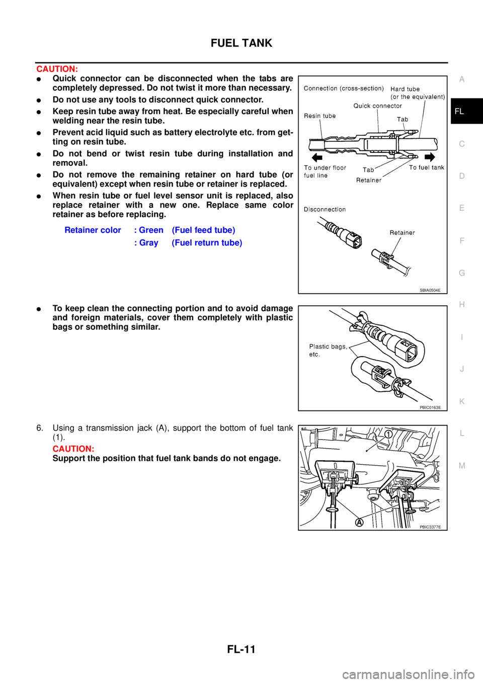
CAUTION:
lQuick connector can be disconnected when the tabs are
completely depressed. Do not twist it more than necessary.
lDo not use any tools to disconnect quick connector.
lKeep resin tube away from heat. Be especially careful when
welding near the resin tube.
lPrevent acid liquid such as battery electrolyte etc. from get-
ting on resin tube.
lDo not bend or twist resin tube during installation and
removal.
lDo not remove the remaining retainer on hard tube (or
equivalent) except when resin tube or retainer is replaced.
lWhen resin tube or fuel level sensor unit is replaced, also
replace retainer with a new one. Replace same color
retainer as before replacing.
lTo keep clean the connecting portion and to avoid damage
and foreign materials, cover them completely with plastic
bags or something similar.
6. Using a transmission jack (A), support the bottom of fuel tank
(1).
CAUTION:
Support the position that fuel tank bands do not engage.Retainer color : Green (Fuel feed tube)
: Gray (Fuel return tube)
SBIA0504E
PBIC0163E
PBIC3377E
Page 1596 of 3171
FL-12
FUEL TANK
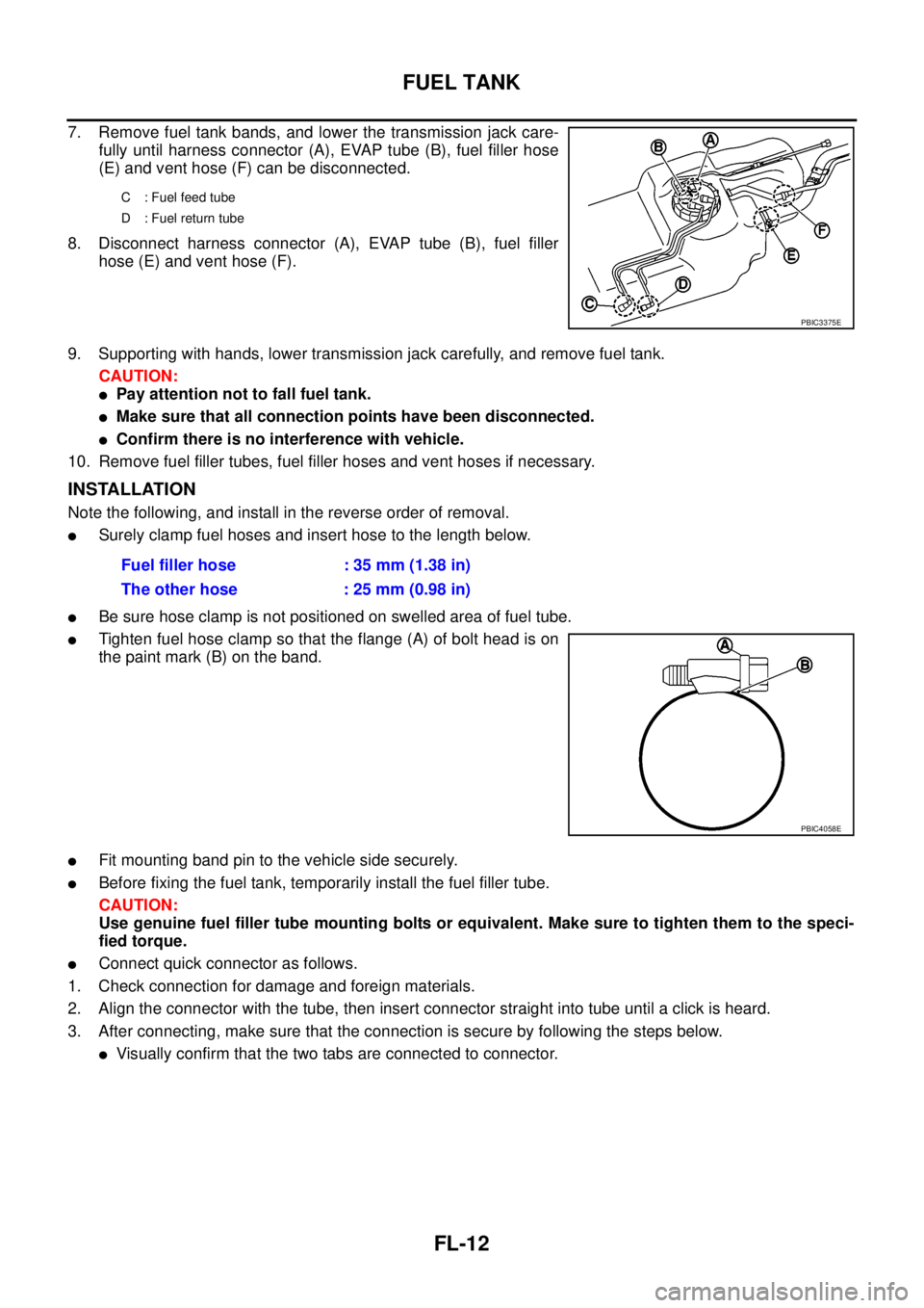
7. Remove fuel tank bands, and lower the transmission jack care-
fully until harness connector (A), EVAP tube (B), fuel filler hose
(E) and vent hose (F) can be disconnected.
8. Disconnect harness connector (A), EVAP tube (B), fuel filler
hose (E) and vent hose (F).
9. Supporting with hands, lower transmission jack carefully, and remove fuel tank.
CAUTION:
lPay attention not to fall fuel tank.
lMake sure that all connection points have been disconnected.
lConfirm there is no interference with vehicle.
10. Remove fuel filler tubes, fuel filler hoses and vent hoses if necessary.
INSTALLATION
Note the following, and install in the reverse order of removal.
lSurely clamp fuel hoses and insert hose to the length below.
lBe sure hose clamp is not positioned on swelled area of fuel tube.
lTighten fuel hose clamp so that the flange (A) of bolt head is on
the paint mark (B) on the band.
lFit mounting band pin to the vehicle side securely.
lBefore fixing the fuel tank, temporarily install the fuel filler tube.
CAUTION:
Use genuine fuel filler tube mounting bolts or equivalent. Make sure to tighten them to the speci-
fied torque.
lConnect quick connector as follows.
1. Check connection for damage and foreign materials.
2. Align the connector with the tube, then insert connector straight into tube until a click is heard.
3. After connecting, make sure that the connection is secure by following the steps below.
lVisually confirm that the two tabs are connected to connector.
C : Fuel feed tube
D : Fuel return tube
PBIC3375E
Fuel filler hose : 35 mm (1.38 in)
The other hose : 25 mm (0.98 in)
PBIC4058E
Page 1598 of 3171
FL-14
FUEL LEVEL SENSOR UNIT
FUEL LEVEL SENSOR UNIT
PFP:17042
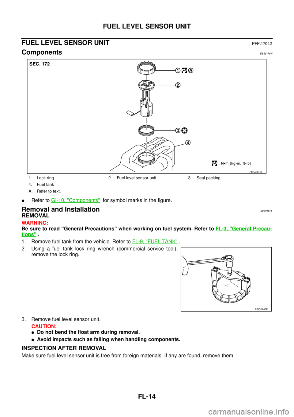
ComponentsEBS01F6N
lRefer toGI-10, "Components"for symbol marks in the figure.
Removal and InstallationEBS01E76
REMOVAL
WARNING:
Be sure to read “General Precautions” when working on fuel system. Refer toFL-3, "
General Precau-
tions".
1. Remove fuel tank from the vehicle. Refer toFL-9, "
FUEL TANK".
2. Using a fuel tank lock ring wrench (commercial service tool),
remove the lock ring.
3. Remove fuel level sensor unit.
CAUTION:
lDo not bend the float arm during removal.
lAvoid impacts such as falling when handling components.
INSPECTION AFTER REMOVAL
Make sure fuel level sensor unit is free from foreign materials. If any are found, remove them.
1. Lock ring 2. Fuel level sensor unit 3. Seal packing
4. Fuel tank
A. Refer to text.
PBIC3374E
PBIC0240E
Page 1599 of 3171
FUEL LEVEL SENSOR UNIT
FL-15
C
D
E
F
G
H
I
J
K
L
MA
FL
INSTALLATION
Note the following, and install in the reverse order of removal.
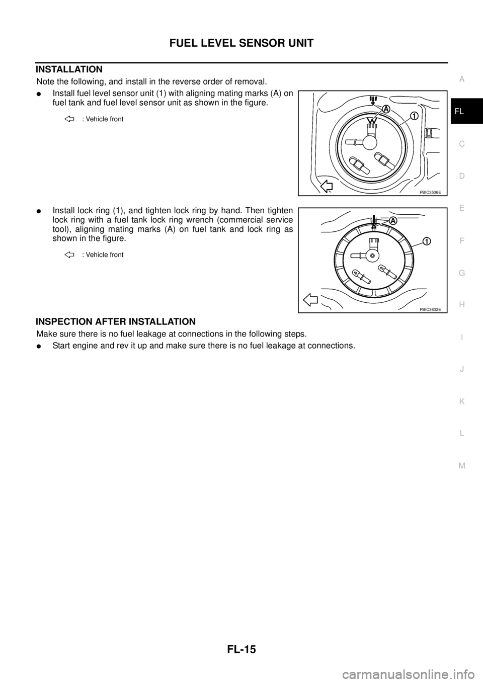
lInstall fuel level sensor unit (1) with aligning mating marks (A) on
fuel tank and fuel level sensor unit as shown in the figure.
lInstall lock ring (1), and tighten lock ring by hand. Then tighten
lock ring with a fuel tank lock ring wrench (commercial service
tool), aligning mating marks (A) on fuel tank and lock ring as
showninthefigure.
INSPECTION AFTER INSTALLATION
Make sure there is no fuel leakage at connections in the following steps.
lStart engine and rev it up and make sure there is no fuel leakage at connections.
: Vehicle front
PBIC3506E
: Vehicle front
PBIC3632E