oil capacity NISSAN NAVARA 2005 Repair Workshop Manual
[x] Cancel search | Manufacturer: NISSAN, Model Year: 2005, Model line: NAVARA, Model: NISSAN NAVARA 2005Pages: 3171, PDF Size: 49.59 MB
Page 19 of 3171
A/T FLUID
AT-11
D
E
F
G
H
I
J
K
L
MA
B
AT
A/T FLUIDPFP:KLE40
Changing A/T FluidECS00FWD
1. Warm up ATF.
2. Stop engine.
3. Loosen level gauge bolt.
4. Remove A/T fluid level gauge.
5. Remove drain plug and drain ATF from drain hole.
6. Install drain plug gasket and drain plug to oil pan.
CAUTION:
Do not reuse drain plug gasket.
7. Tighten drain plug to the specified torque. Refer toAT-218,
"COMPONENTS".
8. Refill with new ATF. Always refill same volume with drained ATF.
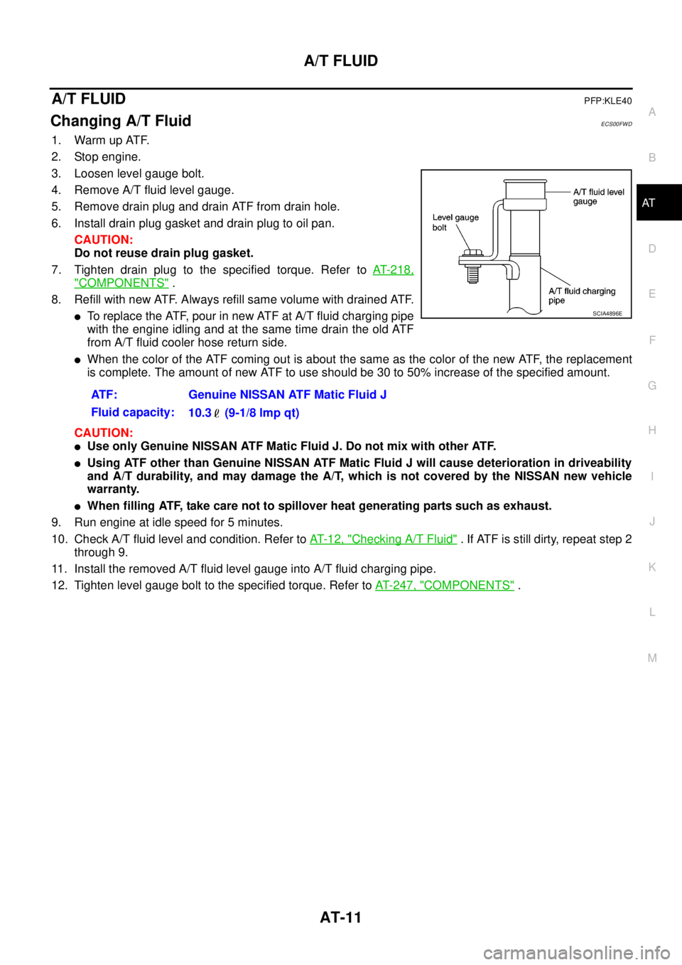
lTo replace the ATF, pour in new ATF at A/T fluid charging pipe
with the engine idling and at the same time drain the old ATF
from A/T fluid cooler hose return side.
lWhen the color of the ATF coming out is about the same as the color of the new ATF, the replacement
is complete. The amount of new ATF to use should be 30 to 50% increase of the specified amount.
CAUTION:
lUse only Genuine NISSAN ATF Matic Fluid J. Do not mix with other ATF.
lUsing ATF other than Genuine NISSAN ATF Matic Fluid J will cause deterioration in driveability
and A/T durability, and may damage the A/T, which is not covered by the NISSAN new vehicle
warranty.
lWhen filling ATF, take care not to spillover heat generating parts such as exhaust.
9. Run engine at idle speed for 5 minutes.
10. Check A/T fluid level and condition. Refer toAT-12, "
Checking A/T Fluid". If ATF is still dirty, repeat step 2
through 9.
11. Install the removed A/T fluid level gauge into A/T fluid charging pipe.
12. Tighten level gauge bolt to the specified torque. Refer toAT- 2 4 7 , "
COMPONENTS". ATF: Genuine NISSAN ATF Matic Fluid J
Fluid capacity:
10.3 (9-1/8 lmp qt)
SCIA4896E
Page 41 of 3171
A/T CONTROL SYSTEM
AT-33
D
E
F
G
H
I
J
K
L
MA
B
AT
Control ValveECS00FWP
FUNCTION OF CONTROL VALVE
FUNCTION OF PRESSURE SWITCH
Name Function
Torque converter regulator valveIn order to prevent the pressure supplied to the torque converter from being excessive, the
line pressure is adjusted to the optimum pressure (torque converter operating pressure).
Pressure regulator valve
Pressure regulator plug
Pressure regulator sleeveAdjusts the oil discharged from the oil pump to the optimum pressure (line pressure) for
the driving state.
Front brake control valveWhen the front brake is coupled, adjusts the line pressure to the optimum pressure (front
brake pressure) and supplies it to the front brake. (In 1st, 2nd, 3rd, and 5th gears, adjusts
theclutchpressure.)
Accumulator control valveAdjusts the pressure (accumulator control pressure) acting on the accumulator piston and
low coast reducing valve to the pressure appropriate to the driving state.
Pilot valve AAdjusts the line pressure and produces the constant pressure (pilot pressure) required for
line pressure control, shift change control, and lock-up control.
Pilot valve BAdjusts the line pressure and produces the constant pressure (pilot pressure) required for
shift change control.
Low coast brake switching valve During engine braking, supplies the line pressure to the low coast brake reducing valve.
Low coast brake reducing valveWhen the low coast brake is coupled, adjusts the line pressure to the optimum pressure
(low coast brake pressure) and supplies it to the low coast brake.
N-R accumulator Produces the stabilizing pressure for when N-R is selected.
Direct clutch piston switching valve Operates in 4th gear and switches the direct clutch coupling capacity.
High and low reverse clutch control valveWhen the high and low reverse clutch is coupled, adjusts the line pressure to the optimum
pressure (high and low reverse clutch pressure) and supplies it to the high and low reverse
clutch. (In 1st, 3rd, 4th and 5th gears, adjusts the clutch pressure.)
Input clutch control valveWhen the input clutch is coupled, adjusts the line pressure to the optimum pressure (input
clutch pressure) and supplies it to the input clutch. (In 4th and 5th gears, adjusts the clutch
pressure.)
Direct clutch control valveWhen the direct clutch is coupled, adjusts the line pressure to the optimum pressure
(direct clutch pressure) and supplies it to the direct clutch. (In 2nd, 3rd, and 4th gears,
adjusts the clutch pressure.)
TCC control valve
TCC control plug
TCC control sleeveSwitches the lock-up to operating or released. Also, by performing the lock-up operation
transiently, lock-up smoothly.
Torque converter lubrication valveOperates during lock-up to switch the torque converter, cooling, and lubrication system oil
path.
Cool bypass valve Allows excess oil to bypass cooler circuit without being fed into it.
Line pressure relief valve Discharges excess oil from line pressure circuit.
N-D accumulator Produces the stabilizing pressure for when N-D is selected.
Manual valveSends line pressure to each circuit according to the select position. The circuits to which
the line pressure is not sent drain.
Name Function
ATFpressureswitch1(FR/B)Detects any malfunction in the front brake hydraulic pressure. When it detects any malfunction,
it puts the system into fail-safe mode.
ATFpressureswitch2(LC/B)Detects any malfunction in the low coast brake hydraulic pressure. When it detects any mal-
function, it puts the system into fail-safe mode.
ATFpressureswitch3(I/C)Detects any malfunction in the input clutch hydraulic pressure. When it detects any malfunction,
it puts the system into fail-safe mode.
ATF pressure switch 5 (D/C)Detects any malfunction in the direct clutch hydraulic pressure. When it detects any malfunc-
tion, it puts the system into fail-safe mode.
ATF pressure switch 6 (HLR/C)Detects any malfunction in the high and low reverse clutch hydraulic pressure. When it detects
any malfunction, it puts the system into fail-safe mode.
Page 352 of 3171
ATC-18
PREPARATION
(J-41459)
HFC-134a (R-134a) dye injector
Use with J-41447, 1/4 ounce
bottleFor injecting 1/4 ounce of fluorescent
leak detection dye into A/C system.
(J-43872)
Refrigerant dye cleanerFor cleaning dye spills.
Manifold gauge set (with hoses
and couplers)Identification:
lThe gauge face indicates HFC-134a
(R-134a).
Fitting size: Thread size
l1/2²-16 ACME
Service hoses
lHigh-pressure side hose
lLow-pressure side hose
lUtility hoseHose color:
lLow hose: Blue with black stripe
lHigh hose: Red with black stripe
lUtility hose: Yellow with black stripe
or green with black stripe
Hose fitting to gauge:
l1/2²-16 ACME
Service couplers
lHigh-pressure side coupler
lLow-pressure side couplerHose fitting to service hose:
M14 x 1.5 fitting is optional or
permanently attached.
Refrigerant weight scaleFor measuring of refrigerant
Fitting size: Thread size
1/2²-16 ACME
Vacuum pump
(Including the isolator valve)Capacity:
lAir displacement: 4 CFM
lMicron rating: 20 microns
lOil capacity: 482 g (17 oz.)
Fitting size: Thread size
l1/2²-16 ACME Tool number
Tool nameDescription
SHA440F
SHA441F
RJIA0196E
S-NT201
S-NT202
S-NT200
S-NT203
Page 1554 of 3171
FFD-8
DIFFERENTIAL GEAR OIL
DIFFERENTIAL GEAR OIL
PFP:KLD30
Changing Differential Gear OilEDS00351
DRAINING
1. Stop the engine.
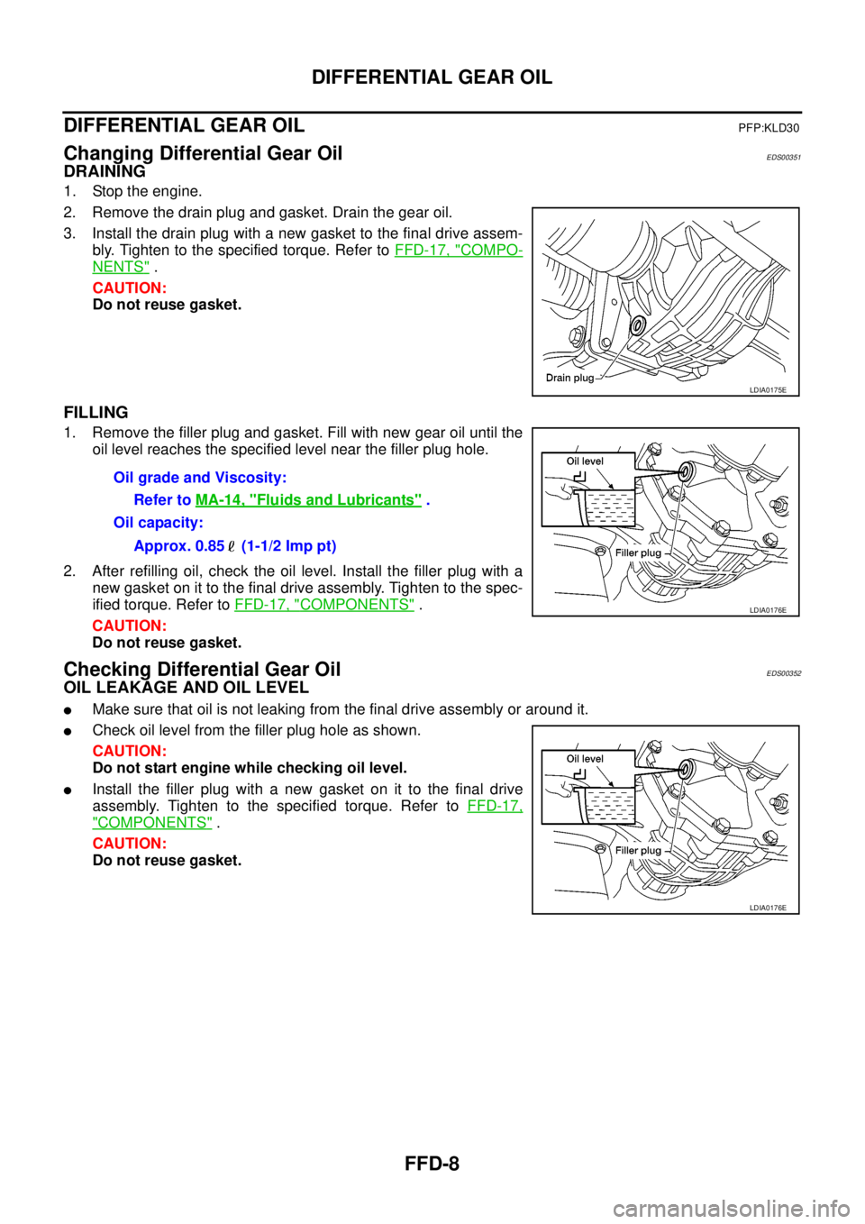
2. Remove the drain plug and gasket. Drain the gear oil.
3. Install the drain plug with a new gasket to the final drive assem-
bly. Tighten to the specified torque. Refer toFFD-17, "
COMPO-
NENTS".
CAUTION:
Do not reuse gasket.
FILLING
1. Remove the filler plug and gasket. Fill with new gear oil until the
oil level reaches the specified level near the filler plug hole.
2. After refilling oil, check the oil level. Install the filler plug with a
new gasket on it to the final drive assembly. Tighten to the spec-
ified torque. Refer toFFD-17, "
COMPONENTS".
CAUTION:
Do not reuse gasket.
Checking Differential Gear OilEDS00352
OIL LEAKAGE AND OIL LEVEL
lMake sure that oil is not leaking from the final drive assembly or around it.
lCheck oil level from the filler plug hole as shown.
CAUTION:
Do not start engine while checking oil level.
lInstall the filler plug with a new gasket on it to the final drive
assembly. Tighten to the specified torque. Refer toFFD-17,
"COMPONENTS".
CAUTION:
Do not reuse gasket.
LDIA0175E
Oil grade and Viscosity:
Refer toMA-14, "
Fluids and Lubricants".
Oil capacity:
Approx. 0.85 (1-1/2 Imp pt)
LDIA0176E
LDIA0176E
Page 1583 of 3171
SERVICE DATA AND SPECIFICATIONS (SDS)
FFD-37
C
E
F
G
H
I
J
K
L
MA
B
FFD
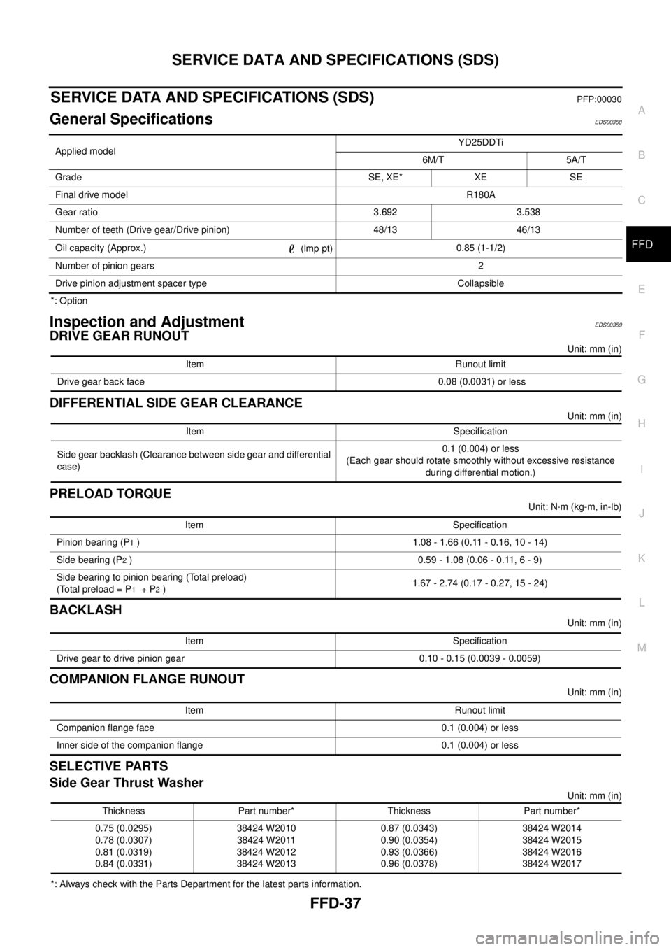
SERVICE DATA AND SPECIFICATIONS (SDS)PFP:00030
General SpecificationsEDS00358
*: Option
Inspection and AdjustmentEDS00359
DRIVE GEAR RUNOUT
Unit: mm (in)
DIFFERENTIAL SIDE GEAR CLEARANCE
Unit: mm (in)
PRELOAD TORQUE
Unit: N·m (kg-m, in-lb)
BACKLASH
Unit: mm (in)
COMPANION FLANGE RUNOUT
Unit: mm (in)
SELECTIVE PARTS
Side Gear Thrust Washer
Unit: mm (in)
*: Always check with the Parts Department for the latest parts information.Applied modelYD25DDTi
6M/T 5A/T
Grade SE, XE* XE SE
Final drive modelR180A
Gear ratio 3.692 3.538
Number of teeth (Drive gear/Drive pinion) 48/13 46/13
Oil capacity (Approx.)
(lmp pt)0.85 (1-1/2)
Number of pinion gears2
Drive pinion adjustment spacer type Collapsible
Item Runout limit
Drive gear back face 0.08 (0.0031) or less
Item Specification
Side gear backlash (Clearance between side gear and differential
case)0.1 (0.004) or less
(Each gear should rotate smoothly without excessive resistance
during differential motion.)
Item Specification
Pinion bearing (P
1) 1.08 - 1.66 (0.11 - 0.16, 10 - 14)
Side bearing (P
2) 0.59 - 1.08 (0.06 - 0.11, 6 - 9)
Side bearing to pinion bearing (Total preload)
(Total preload = P
1+P2)1.67 - 2.74 (0.17 - 0.27, 15 - 24)
Item Specification
Drive gear to drive pinion gear 0.10 - 0.15 (0.0039 - 0.0059)
Item Runout limit
Companion flange face 0.1 (0.004) or less
Inner side of the companion flange 0.1 (0.004) or less
Thickness Part number* Thickness Part number*
0.75 (0.0295)
0.78 (0.0307)
0.81 (0.0319)
0.84 (0.0331)38424 W2010
38424 W2011
38424 W2012
38424 W20130.87 (0.0343)
0.90 (0.0354)
0.93 (0.0366)
0.96 (0.0378)38424 W2014
38424 W2015
38424 W2016
38424 W2017
Page 2258 of 3171
LU-1
ENGINE LUBRICATION SYSTEM
B ENGINE
CONTENTS
C
D
E
F
G
H
I
J
K
L
M
SECTIONLU
A
LU
ENGINE LUBRICATION SYSTEM
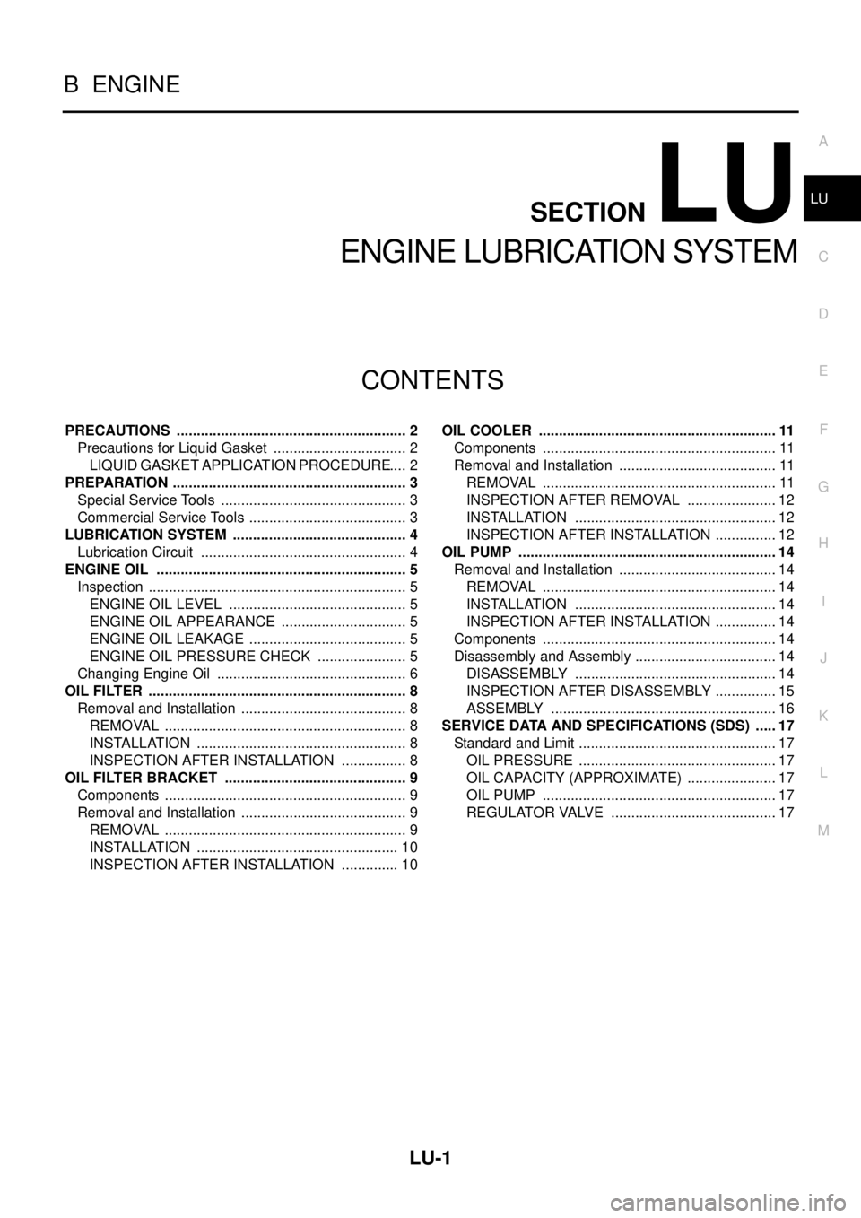
PRECAUTIONS .......................................................... 2
Precautions for Liquid Gasket .................................. 2
LIQUID GASKET APPLICATION PROCEDURE..... 2
PREPARATION ........................................................... 3
Special Service Tools ............................................... 3
Commercial Service Tools ........................................ 3
LUBRICATION SYSTEM ............................................ 4
Lubrication Circuit .................................................... 4
ENGINE OIL ............................................................... 5
Inspection ................................................................. 5
ENGINE OIL LEVEL ............................................. 5
ENGINE OIL APPEARANCE ................................ 5
ENGINE OIL LEAKAGE ........................................ 5
ENGINE OIL PRESSURE CHECK ....................... 5
Changing Engine Oil ................................................ 6
OIL FILTER ................................................................. 8
Removal and Installation .......................................... 8
REMOVAL ............................................................. 8
INSTALLATION ..................................................... 8
INSPECTION AFTER INSTALLATION ................. 8
OIL FILTER BRACKET .............................................. 9
Components ............................................................. 9
Removal and Installation .......................................... 9
REMOVAL ............................................................. 9
INSTALLATION ................................................... 10
INSPECTION AFTER INSTALLATION ............... 10OIL COOLER ............................................................ 11
Components ........................................................... 11
Removal and Installation ........................................ 11
REMOVAL ........................................................... 11
INSPECTION AFTER REMOVAL ....................... 12
INSTALLATION ................................................... 12
INSPECTION AFTER INSTALLATION ................ 12
OIL PUMP ................................................................. 14
Removal and Installation ........................................ 14
REMOVAL ........................................................... 14
INSTALLATION ................................................... 14
INSPECTION AFTER INSTALLATION ................ 14
Components ........................................................... 14
Disassembly and Assembly .................................... 14
DISASSEMBLY ................................................... 14
INSPECTION AFTER DISASSEMBLY ................ 15
ASSEMBLY ......................................................... 16
SERVICE DATA AND SPECIFICATIONS (SDS) ...... 17
Standard and Limit .................................................. 17
OIL PRESSURE .................................................. 17
OIL CAPACITY (APPROXIMATE) ....................... 17
OIL PUMP ........................................................... 17
REGULATOR VALVE .......................................... 17
Page 2264 of 3171
ENGINE OIL
LU-7
C
D
E
F
G
H
I
J
K
L
MA
LU
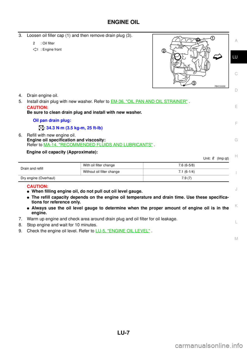
3. Loosen oil filler cap (1) and then remove drain plug (3).
4. Drain engine oil.
5. Install drain plug with new washer. Refer toEM-36, "
OIL PAN AND OIL STRAINER".
CAUTION:
Be sure to clean drain plug and install with new washer.
6. Refill with new engine oil.
Engine oil specification and viscosity:
Refer toMA-14, "
RECOMMENDED FLUIDS AND LUBRICANTS".
Engine oil capacity (Approximate):
Unit: (lmp qt)
CAUTION:
lWhen filling engine oil, do not pull out oil level gauge.
lThe refill capacity depends on the engine oil temperature and drain time. Use these specifica-
tions for reference only.
lAlways use the oil level gauge to determine when the proper amount of engine oil is in the
engine.
7. Warm up engine and check area around drain plug and oil filter for oil leakage.
8. Stop engine and wait for 10 minutes.
9. Check the engine oil level. Refer toLU-5, "
ENGINE OIL LEVEL".
2 : Oil filter
: Engine front
PBIC3335E
Oil pan drain plug:
: 34.3 N·m (3.5 kg-m, 25 ft-lb)
Drain and refillWith oil filter change 7.6 (6-5/8)
Without oil filter change 7.1 (6-1/4)
Dry engine (Overhaul)7.9 (7)
Page 2274 of 3171
SERVICE DATA AND SPECIFICATIONS (SDS)
LU-17
C
D
E
F
G
H
I
J
K
L
MA
LU
SERVICE DATA AND SPECIFICATIONS (SDS)PFP:00030
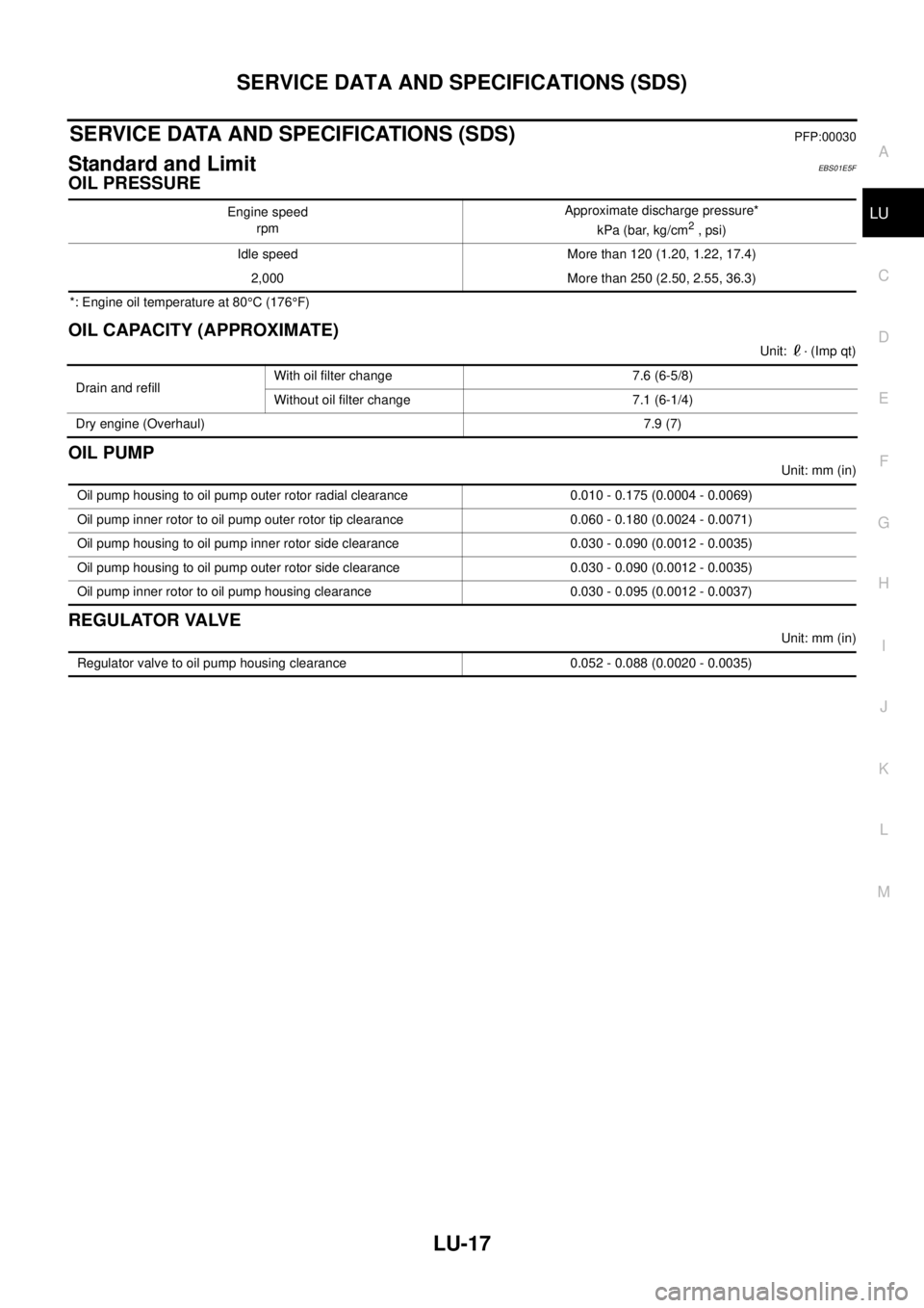
Standard and LimitEBS01E5F
OIL PRESSURE
*: Engine oil temperature at 80°C (176°F)
OIL CAPACITY (APPROXIMATE)
Unit: · (Imp qt)
OIL PUMP
Unit: mm (in)
REGULATOR VALVE
Unit: mm (in) Engine speed
rpmApproximate discharge pressure*
kPa (bar, kg/cm
2, psi)
Idle speed More than 120 (1.20, 1.22, 17.4)
2,000 More than 250 (2.50, 2.55, 36.3)
Drain and refillWith oil filter change 7.6 (6-5/8)
Without oil filter change 7.1 (6-1/4)
Dry engine (Overhaul)7.9 (7)
Oil pump housing to oil pump outer rotor radial clearance 0.010 - 0.175 (0.0004 - 0.0069)
Oil pump inner rotor to oil pump outer rotor tip clearance 0.060 - 0.180 (0.0024 - 0.0071)
Oil pump housing to oil pump inner rotor side clearance 0.030 - 0.090 (0.0012 - 0.0035)
Oil pump housing to oil pump outer rotor side clearance 0.030 - 0.090 (0.0012 - 0.0035)
Oil pump inner rotor to oil pump housing clearance 0.030 - 0.095 (0.0012 - 0.0037)
Regulator valve to oil pump housing clearance 0.052 - 0.088 (0.0020 - 0.0035)
Page 2277 of 3171

MA-2
Checking Rear Final Drive Oil (Rear Differential
Gear Oil) ................................................................. 33
OIL LEAKAGE AND OIL LEVEL ......................... 33
Changing Rear Final Drive Oil (Rear Differential
Gear Oil) ................................................................. 34
DRAINING ........................................................... 34
FILLING ............................................................... 34
Balancing Wheels ................................................... 34
Tire Rotation ........................................................... 34
Checking Brake Fluid Level and Leaks .................. 35
Checking Brake Lines and Cables ......................... 35
Changing Brake Fluid ............................................. 35
Checking Disc Brake .............................................. 35
ROTOR ................................................................ 35
CALIPER ............................................................. 36
PAD ..................................................................... 36
Checking Drum Brake ............................................ 36
DRUM .................................................................. 36
WHEEL CYLINDER ............................................. 36
LINING ................................................................. 37
Checking Steering Gear and Linkage ..................... 37
STEERING GEAR ............................................... 37
STEERING LINKAGE .......................................... 37
Checking Power Steering Fluid and Lines .............. 37CHECKING FLUID LEVEL .................................. 37
CHECKING LINES ............................................... 37
Checking Axle and Suspension Parts ..................... 38
FRONT AND REAR AXLE AND SUSPENSION
PARTS ................................................................. 38
FRONT DRIVE SHAFT ........................................ 38
Lubricating Locks, Hinges and Hood Latches ......... 39
Checking Seat Belts, Buckles, Retractors, Anchors
and Adjusters .......................................................... 40
Checking Body Corrosion ....................................... 40
HEMMED PANELS .............................................. 40
PANEL JOINT ...................................................... 40
PANEL EDGE ...................................................... 40
PARTS CONTACT ............................................... 40
PROTECTORS .................................................... 40
ANTI-CORROSION MATERIALS ........................ 40
DRAIN HOLES ..................................................... 40
SERVICE DATA AND SPECIFICATIONS (SDS) ...... 41
Standard and Limit .................................................. 41
BELT DEFLECTION ............................................ 41
RESERVOIR TANK ............................................. 41
ENGINE COOLANT CAPACITY (APPROXI-
MATE) .................................................................. 41
ENGINE OIL CAPACITY (APPROXIMATE) ........ 41
Page 2289 of 3171

MA-14
RECOMMENDED FLUIDS AND LUBRICANTS
RECOMMENDED FLUIDS AND LUBRICANTS
PFP:00000
Fluids and LubricantsELS001JA
*1: For further details, see “SAE Viscosity Number”.
*2: Never use API CG-4.
*3: Use Genuine NISSAN Anti-freeze Coolant (L250) or equivalent in its quality, in order to avoid possible aluminum corrosion within the
engine cooling system caused by the use of non-genuine engine coolant.
Note that any repairs for the incidents within the engine cooling system while using non-genuine engine coolant may not be
covered by the warranty even if such incidents occurred during the warranty period.
*4: Contact a Nissan dealership for more information regarding suitable fluids, including recommended brand(s) of DEXRON
™III/MER-
CON™ Automatic Transmission Fluid.
*5:Using automatic transmission fluid other than Genuine NISSAN ATF Matic Fluid J will cause deterioration in driveability
and automatic transmission durability, and may damage the automatic transmission, which is not covered by the warranty.
*6: DEXRON™III type ATF can be used.
*7: Never mix different types of fluids (DOT 3 and DOT 4).Capacity (Approximate)
Recommended Fluids/Lubricants
Liter Imp measure
Engine oil
Drain and refillWith oil filter change 7.6 6-5/8 qt
lDiesel engine
API CF-4*1, *2
ACEA B1, B3, B4, B5*1 Without oil filter change 7.1 6-1/4 qt
Dry engine (engine overhaul) 7.9 7 qt
Cooling sys-
tem (with res-
ervoir)LHD models 9.9 8-3/4 qt
lGenuine NISSAN Anti-freeze Coolant (L250) or
equivalent in its quality*3 RHD models 10.2 9 qt
Reservoir tank 0.8 3/4 qt
Manual transmission gear oil2WD 3.99 7 pt
lGenuine NISSAN gear oil or API GL-4, Viscosity
SAE 75W-85 or 75W-90
4WD 4.32 7-5/8 pt
Transfer fluid 2.0 1-3/4 qt
lGenuine NISSAN ATF or equivalent*4
Differential gear oilFront 0.85 1-1/2 pt
lStandard differential gear:
Gear Oil Hypoid LSD (Part No.: KLD31-8090403)
or API GL-5, Viscosity SAE 80W-90*1
lLimited-slip differential (LSD) gear:
Gear Oil Hypoid LSD (Part No. KLD31-8090403)
or equivalent Rear 2.01 3-1/2 pt
Automatic transmission fluid 10.3 9-1/8 qt Genuine NISSAN ATF Matic Fluid J*5
Power steering fluid — — Genuine NISSAN PSF or equivalent*6
Brake and clutch fluid — —
lDOT 3 or DOT 4 (US FMVSS No. 116)*7
Multi-purpose grease — — NLGI No. 2 (Lithium soap base)