power steering fluid NISSAN NAVARA 2005 Repair Workshop Manual
[x] Cancel search | Manufacturer: NISSAN, Model Year: 2005, Model line: NAVARA, Model: NISSAN NAVARA 2005Pages: 3171, PDF Size: 49.59 MB
Page 602 of 3171
BL-18
RADIATOR CORE SUPPORT
RADIATOR CORE SUPPORT
PFP:62500
Removal and InstallationEIS00DGJ
REMOVAL
1. Remove the hood assembly. Refer toBL-14, "Removal and Installation of Hood Assembly".
2. Remove the front grille. Refer toEI-19, "
FRONT GRILLE".
3. Remove the front bumper, bumper reinforcement and bumper bracket. Refer toEI-15, "
FRONT BUMPER"
.
4. Remove the headlamp assembly (LH/RH). Refer toLT-30, "
Removal and Installation".
5. Remove the air intake duct (Air guide). Refer toEM-15, "
AIR CLEANER AND AIR DUCT".
6. Remove the charge air cooler. (for YD25 engine models only) Refer toEM-18, "
CHARGE AIR COOLER".
7. Remove the power steering oil cooler. Refer toPS-30, "
HYDRAULIC LINE".
8. Remove the A/T fluid cooler and A/T fluid cooler tube mounting nuts. Refer toAT- 2 4 4 , "
A/T FLUID
COOLER".
9. Remove the hood lock assembly, and then remove the hood lock cable. Refer toBL-15, "
Removal and
Installation of Hood Lock Control".
10. Remove the horn harness connector.
11. Disconnect the ambient sensor connector and remove the ambient sensor. Refer toAT C - 11 7 , "
Removal
and Installation".
12. Remove the mounting harness clip on radiator core support assembly, the harness is separate.
13. Remove the upper radiator bracket. Refer toCO-11, "
RADIATOR".
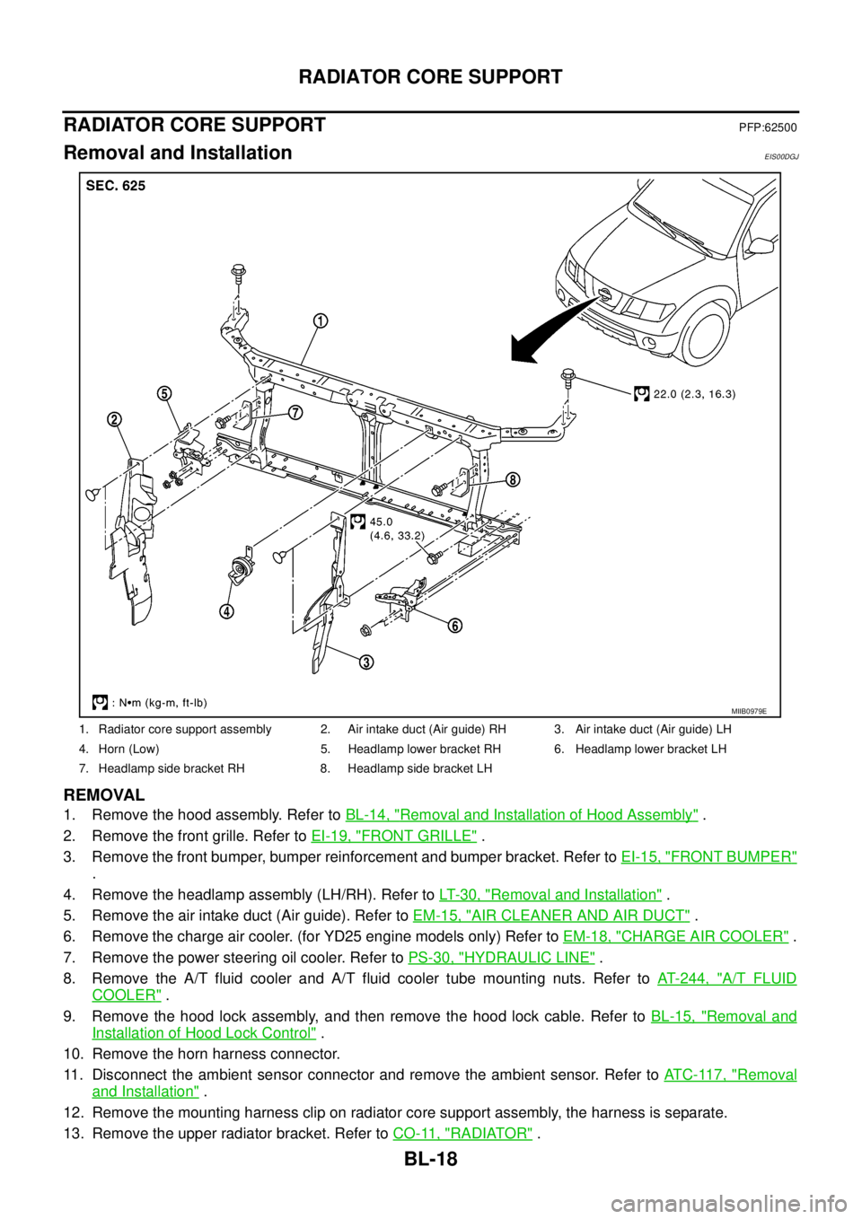
1. Radiator core support assembly 2. Air intake duct (Air guide) RH 3. Air intake duct (Air guide) LH
4. Horn (Low) 5. Headlamp lower bracket RH 6. Headlamp lower bracket LH
7. Headlamp side bracket RH 8. Headlamp side bracket LH
MIIB0979E
Page 1447 of 3171
CAMSHAFT
EM-65
C
D
E
F
G
H
I
J
K
L
MA
EM
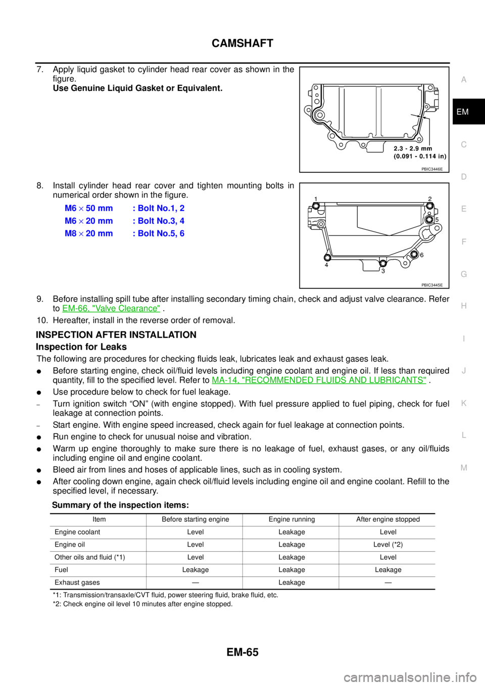
7. Apply liquid gasket to cylinder head rear cover as shown in the
figure.
Use Genuine Liquid Gasket or Equivalent.
8. Install cylinder head rear cover and tighten mounting bolts in
numerical order shown in the figure.
9. Before installing spill tube after installing secondary timing chain, check and adjust valve clearance. Refer
toEM-66, "
Valve Clearance".
10. Hereafter, install in the reverse order of removal.
INSPECTION AFTER INSTALLATION
Inspection for Leaks
The following are procedures for checking fluids leak, lubricates leak and exhaust gases leak.
lBefore starting engine, check oil/fluid levels including engine coolant and engine oil. If less than required
quantity, fill to the specified level. Refer toMA-14, "
RECOMMENDED FLUIDS AND LUBRICANTS".
lUse procedure below to check for fuel leakage.
–Turn ignition switch “ON” (with engine stopped). With fuel pressure applied to fuel piping, check for fuel
leakage at connection points.
–Start engine. With engine speed increased, check again for fuel leakage at connection points.
lRun engine to check for unusual noise and vibration.
lWarm up engine thoroughly to make sure there is no leakage of fuel, exhaust gases, or any oil/fluids
including engine oil and engine coolant.
lBleed air from lines and hoses of applicable lines, such as in cooling system.
lAfter cooling down engine, again check oil/fluid levels including engine oil and engine coolant. Refill to the
specified level, if necessary.
Summary of the inspection items:
*1: Transmission/transaxle/CVT fluid, power steering fluid, brake fluid, etc.
*2: Check engine oil level 10 minutes after engine stopped.
PBIC3446E
M6´50 mm : Bolt No.1, 2
M6´20 mm : Bolt No.3, 4
M8´20 mm : Bolt No.5, 6
PBIC3445E
Item Before starting engine Engine running After engine stopped
Engine coolant Level Leakage Level
Engine oil Level Leakage Level (*2)
Other oils and fluid (*1) Level Leakage Level
Fuel Leakage Leakage Leakage
Exhaust gases — Leakage —
Page 1460 of 3171
EM-78
SECONDARY TIMING CHAIN
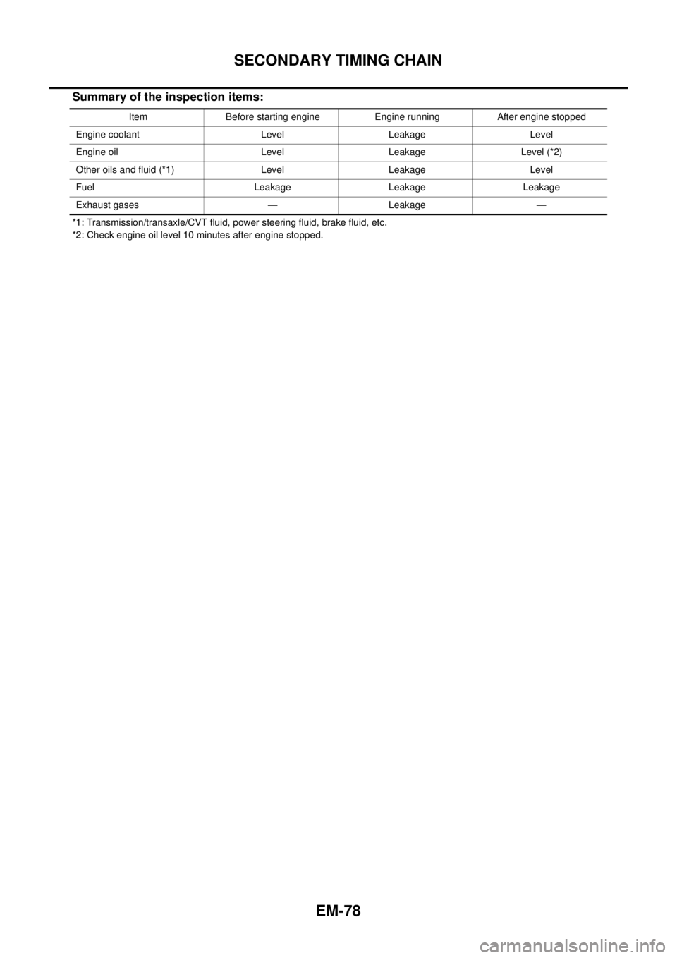
Summary of the inspection items:
*1: Transmission/transaxle/CVT fluid, power steering fluid, brake fluid, etc.
*2: Check engine oil level 10 minutes after engine stopped.Item Before starting engine Engine running After engine stopped
Engine coolant Level Leakage Level
Engine oil Level Leakage Level (*2)
Other oils and fluid (*1) Level Leakage Level
Fuel Leakage Leakage Leakage
Exhaust gases — Leakage —
Page 1473 of 3171
PRIMARY TIMING CHAIN
EM-91
C
D
E
F
G
H
I
J
K
L
MA
EM
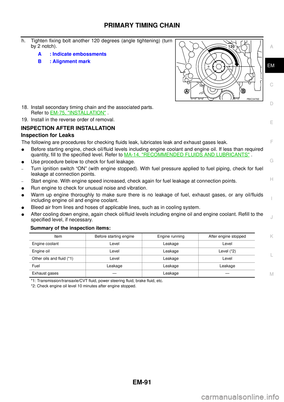
h. Tighten fixing bolt another 120 degrees (angle tightening) (turn
by 2 notch).
18. Install secondary timing chain and the associated parts.
Refer toEM-75, "
INSTALLATION".
19. Install in the reverse order of removal.
INSPECTION AFTER INSTALLATION
Inspection for Leaks
The following are procedures for checking fluids leak, lubricates leak and exhaust gases leak.
lBefore starting engine, check oil/fluid levels including engine coolant and engine oil. If less than required
quantity, fill to the specified level. Refer toMA-14, "
RECOMMENDED FLUIDS AND LUBRICANTS".
lUse procedure below to check for fuel leakage.
–Turn ignition switch “ON” (with engine stopped). With fuel pressure applied to fuel piping, check for fuel
leakage at connection points.
–Start engine. With engine speed increased, check again for fuel leakage at connection points.
lRun engine to check for unusual noise and vibration.
lWarm up engine thoroughly to make sure there is no leakage of fuel, exhaust gases, or any oil/fluids
including engine oil and engine coolant.
lBleed air from lines and hoses of applicable lines, such as in cooling system.
lAfter cooling down engine, again check oil/fluid levels including engine oil and engine coolant. Refill to the
specified level, if necessary.
Summary of the inspection items:
*1: Transmission/transaxle/CVT fluid, power steering fluid, brake fluid, etc.
*2: Check engine oil level 10 minutes after engine stopped.
A : Indicate embossments
B : Alignment mark
PBIC3476E
Item Before starting engine Engine running After engine stopped
Engine coolant Level Leakage Level
Engine oil Level Leakage Level (*2)
Other oils and fluid (*1) Level Leakage Level
Fuel Leakage Leakage Leakage
Exhaust gases — Leakage —
Page 1480 of 3171
EM-98
CYLINDER HEAD
lBefore installing, remove carbon depositing on mounting hole of glow plug with a reamer.
6. Install engine coolant temperature sensor.
7. Install in the reverse order of removal.
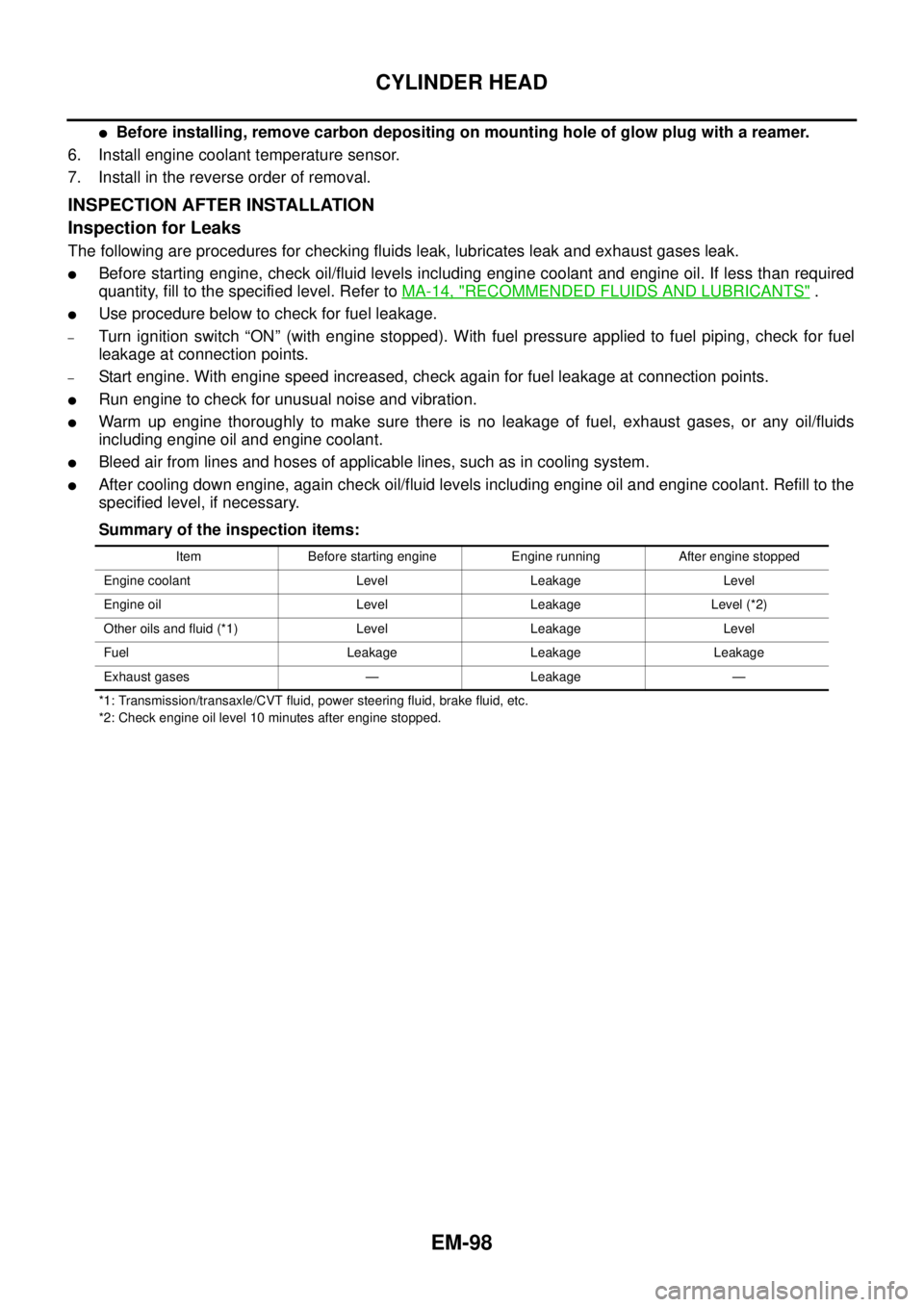
INSPECTION AFTER INSTALLATION
Inspection for Leaks
The following are procedures for checking fluids leak, lubricates leak and exhaust gases leak.
lBefore starting engine, check oil/fluid levels including engine coolant and engine oil. If less than required
quantity, fill to the specified level. Refer toMA-14, "
RECOMMENDED FLUIDS AND LUBRICANTS".
lUse procedure below to check for fuel leakage.
–Turn ignition switch “ON” (with engine stopped). With fuel pressure applied to fuel piping, check for fuel
leakage at connection points.
–Start engine. With engine speed increased, check again for fuel leakage at connection points.
lRun engine to check for unusual noise and vibration.
lWarm up engine thoroughly to make sure there is no leakage of fuel, exhaust gases, or any oil/fluids
including engine oil and engine coolant.
lBleed air from lines and hoses of applicable lines, such as in cooling system.
lAfter cooling down engine, again check oil/fluid levels including engine oil and engine coolant. Refill to the
specified level, if necessary.
Summary of the inspection items:
*1: Transmission/transaxle/CVT fluid, power steering fluid, brake fluid, etc.
*2: Check engine oil level 10 minutes after engine stopped.Item Before starting engine Engine running After engine stopped
Engine coolant Level Leakage Level
Engine oil Level Leakage Level (*2)
Other oils and fluid (*1) Level Leakage Level
Fuel Leakage Leakage Leakage
Exhaust gases — Leakage —
Page 1489 of 3171
ENGINE ASSEMBLY
EM-107
C
D
E
F
G
H
I
J
K
L
MA
EM
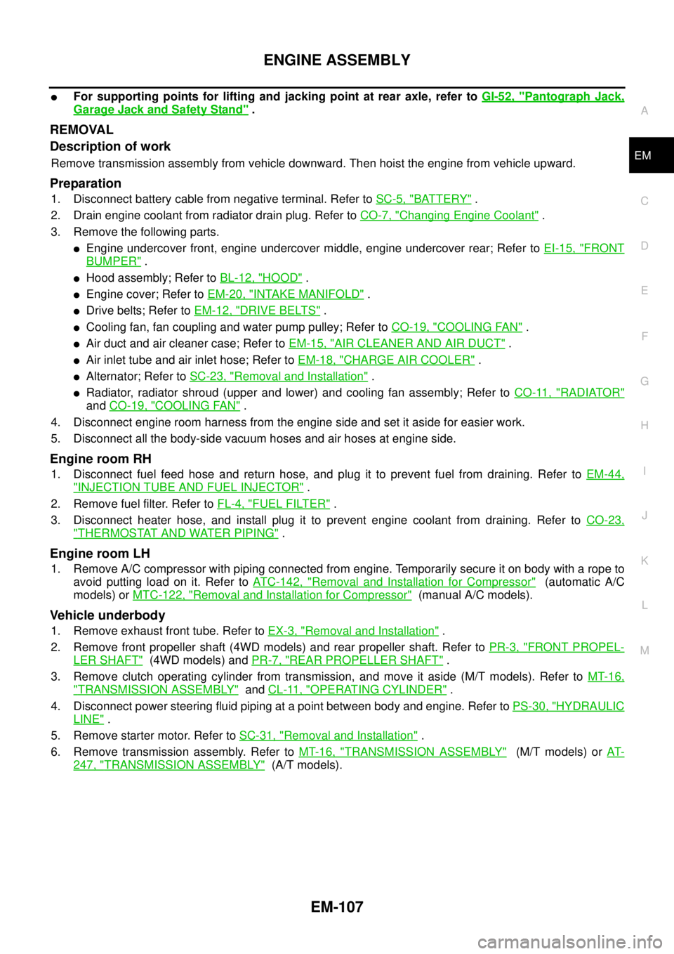
lFor supporting points for lifting and jacking point at rear axle, refer toGI-52, "Pantograph Jack,
Garage Jack and Safety Stand".
REMOVAL
Description of work
Remove transmission assembly from vehicle downward. Then hoist the engine from vehicle upward.
Preparation
1. Disconnect battery cable from negative terminal. Refer toSC-5, "BATTERY".
2. Drain engine coolant from radiator drain plug. Refer toCO-7, "
Changing Engine Coolant".
3. Remove the following parts.
lEngine undercover front, engine undercover middle, engine undercover rear; Refer toEI-15, "FRONT
BUMPER".
lHood assembly; Refer toBL-12, "HOOD".
lEngine cover; Refer toEM-20, "INTAKE MANIFOLD".
lDrive belts; Refer toEM-12, "DRIVE BELTS".
lCooling fan, fan coupling and water pump pulley; Refer toCO-19, "COOLING FAN".
lAir duct and air cleaner case; Refer toEM-15, "AIR CLEANER AND AIR DUCT".
lAir inlet tube and air inlet hose; Refer toEM-18, "CHARGE AIR COOLER".
lAlternator; Refer toSC-23, "Removal and Installation".
lRadiator, radiator shroud (upper and lower) and cooling fan assembly; Refer toCO-11, "RADIATOR"
andCO-19, "COOLING FAN".
4. Disconnect engine room harness from the engine side and set it aside for easier work.
5. Disconnect all the body-side vacuum hoses and air hoses at engine side.
Engine room RH
1. Disconnect fuel feed hose and return hose, and plug it to prevent fuel from draining. Refer toEM-44,
"INJECTION TUBE AND FUEL INJECTOR".
2. Remove fuel filter. Refer toFL-4, "
FUEL FILTER".
3. Disconnect heater hose, and install plug it to prevent engine coolant from draining. Refer toCO-23,
"THERMOSTAT AND WATER PIPING".
Engine room LH
1. Remove A/C compressor with piping connected from engine. Temporarily secure it on body with a rope to
avoid putting load on it. Refer toATC-142, "
Removal and Installation for Compressor"(automatic A/C
models) orMTC-122, "
Removal and Installation for Compressor"(manual A/C models).
Vehicle underbody
1. Remove exhaust front tube. Refer toEX-3, "Removal and Installation".
2. Remove front propeller shaft (4WD models) and rear propeller shaft. Refer toPR-3, "
FRONT PROPEL-
LER SHAFT"(4WD models) andPR-7, "REAR PROPELLER SHAFT".
3. Remove clutch operating cylinder from transmission, and move it aside (M/T models). Refer toMT-16,
"TRANSMISSION ASSEMBLY"andCL-11, "OPERATING CYLINDER".
4. Disconnect power steering fluid piping at a point between body and engine. Refer toPS-30, "
HYDRAULIC
LINE".
5. Remove starter motor. Refer toSC-31, "
Removal and Installation".
6. Remove transmission assembly. Refer toMT-16, "
TRANSMISSION ASSEMBLY"(M/T models) orAT-
247, "TRANSMISSION ASSEMBLY"(A/T models).
Page 1491 of 3171
ENGINE ASSEMBLY
EM-109
C
D
E
F
G
H
I
J
K
L
MA
EM
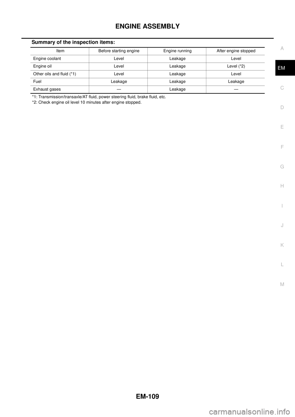
Summary of the inspection items:
*1: Transmission/transaxle/AT fluid, power steering fluid, brake fluid, etc.
*2: Check engine oil level 10 minutes after engine stopped.Item Before starting engine Engine running After engine stopped
Engine coolant Level Leakage Level
Engine oil Level Leakage Level (*2)
Other oils and fluid (*1) Level Leakage Level
Fuel Leakage Leakage Leakage
Exhaust gases — Leakage —
Page 1562 of 3171
FFD-16
FRONT FINAL DRIVE ASSEMBLY
CAUTION:
Do not pull on the ABS sensor harness.
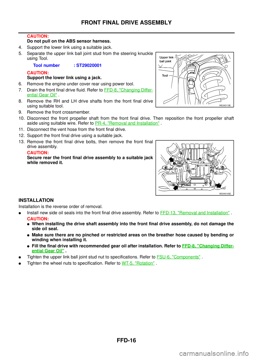
4. Support the lower link using a suitable jack.
5. Separate the upper link ball joint stud from the steering knuckle
using Tool.
CAUTION:
Support the lower link using a jack.
6. Remove the engine under cover rear using power tool.
7. Drain the front final drive fluid. Refer toFFD-8, "
Changing Differ-
ential Gear Oil".
8. Remove the RH and LH drive shafts from the front final drive
using suitable tool.
9. Remove the front crossmember.
10. Disconnect the front propeller shaft from the front final drive. Then reposition the front propeller shaft
aside using suitable wire. Refer toPR-4, "
Removal and Installation".
11. Disconnect the vent hose from the front final drive.
12. Support the front final drive using a suitable jack.
13. Remove the front final drive bolts, then remove the front final
drive assembly.
CAUTION:
Secure rear the front final drive assembly to a suitable jack
while removed it.
INSTALLATION
Installation is the reverse order of removal.
lInstall new side oil seals into the front final drive assembly. Refer toFFD-13, "Removal and Installation".
CAUTION:
lWhen installing the drive shaft assembly into the front final drive assembly, do not damage the
side oil seal.
lMake sure there are no pinched or restricted areas on the breather hose caused by bending or
winding when installing it.
lFill the final drive with recommended gear oil after installation. Refer toFFD-8, "Changing Differ-
ential Gear Oil".
lTighten the upper link ball joint stud nut to specifications. Refer toFSU-6, "Components".
lTighten the wheel nuts to specification. Refer toWT-5, "Rotation". Tool number : ST29020001
WEIA0119E
WDIA0145E
Page 1645 of 3171
HOW TO USE THIS MANUAL
GI-23
C
D
E
F
G
H
I
J
K
L
MB
GI
AbbreviationsEAS001GZ
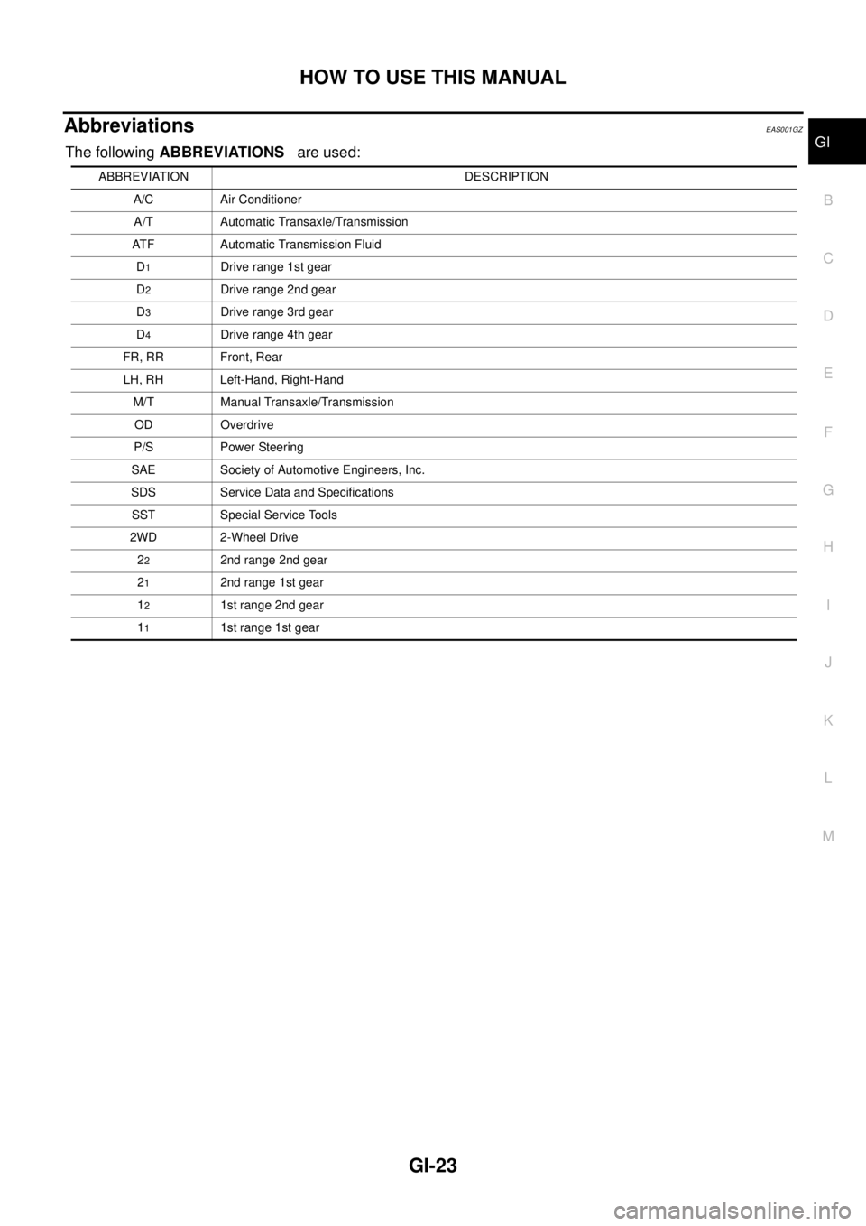
The followingABBREVIATIONSare used:
ABBREVIATION DESCRIPTION
A/C Air Conditioner
A/T Automatic Transaxle/Transmission
ATF Automatic Transmission Fluid
D
1Drive range 1st gear
D
2Drive range 2nd gear
D
3Drive range 3rd gear
D
4Drive range 4th gear
FR, RR Front, Rear
LH, RH Left-Hand, Right-Hand
M/T Manual Transaxle/Transmission
OD Overdrive
P/S Power Steering
SAE Society of Automotive Engineers, Inc.
SDS Service Data and Specifications
SST Special Service Tools
2WD 2-Wheel Drive
2
22nd range 2nd gear
2
12nd range 1st gear
1
21st range 2nd gear
1
11st range 1st gear
Page 1758 of 3171
IDX-6
ALPHABETICAL INDEX
P
P/SCKT - Wiring diagram ................................WW-57
Park/Neutral position switch ............................EC-342
Park/neutral position switch (A/T) ......................AT-99
Park/neutral position switch (M/T) ........MT-12,MT-19
Parking brake control ...........................................PB-2
Personal lamp ...................................................LT-145
Pilot bushing replacement ..............................EM-111
Piston pin inspection .......................................EM-125
Piston ring inspection ......................................EM-126
Piston to bore clearance .................................EM-129
Planetary carrier (Transfer) ..............................TF-129
PNP/SW - Wiring diagram ...............................EC-343
POWER - Wiring diagram ....................................PG-5
Power seat .........................................................SE-10
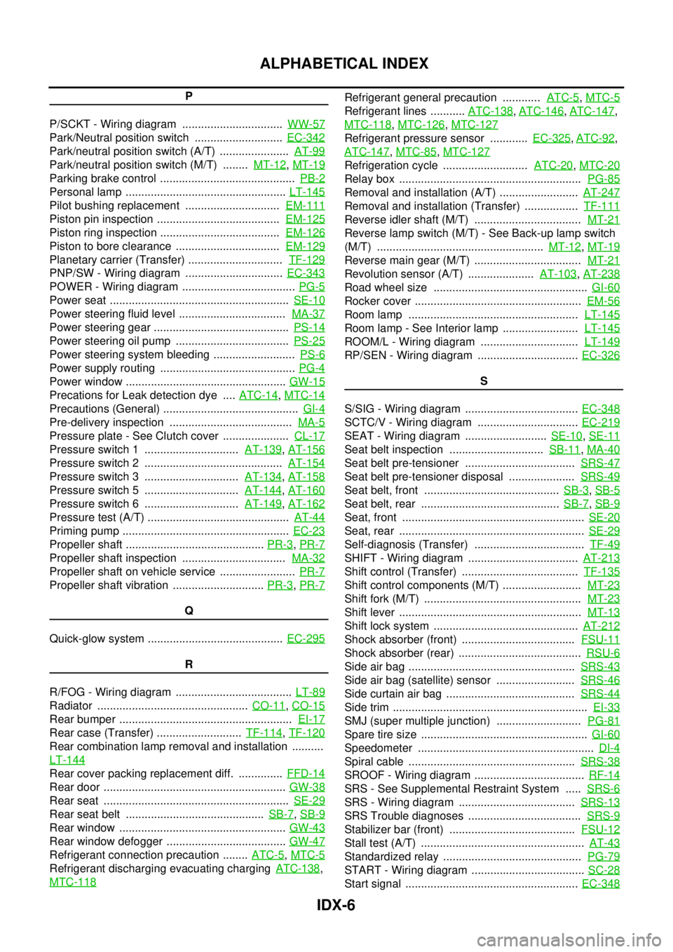
Power steering fluid level ..................................MA-37
Power steering gear ...........................................PS-14
Power steering oil pump ....................................PS-25
Power steering system bleeding ..........................PS-6
Power supply routing ...........................................PG-4
Power window ...................................................GW-15
Precations for Leak detection dye ....ATC-14,MTC-14
Precautions (General) ...........................................GI-4
Pre-delivery inspection .......................................MA-5
Pressure plate - See Clutch cover .....................CL-17
Pressure switch 1 ..............................AT-139,AT-156
Pressure switch 2 ............................................AT-154
Pressure switch 3 ..............................AT-134,AT-158
Pressure switch 5 ..............................AT-144,AT-160
Pressure switch 6 ..............................AT-149,AT-162
Pressure test (A/T) .............................................AT-44
Priming pump .....................................................EC-23
Propeller shaft ............................................PR-3,PR-7
Propeller shaft inspection .................................MA-32
Propeller shaft on vehicle service ........................PR-7
Propeller shaft vibration .............................PR-3,PR-7
Q
Quick-glow system ...........................................EC-295
R
R/FOG - Wiring diagram .....................................LT-89
Radiator ................................................CO-11,CO-15
Rear bumper .......................................................EI-17
Rear case (Transfer) ...........................TF-114,TF-120
Rear combination lamp removal and installation ..........
LT-144
Rear cover packing replacement diff. ..............FFD-14
Rear door ..........................................................GW-38
Rear seat ...........................................................SE-29
Rear seat belt ............................................SB-7,SB-9
Rear window .....................................................GW-43
Rear window defogger ......................................GW-47
Refrigerant connection precaution ........ATC-5,MTC-5
Refrigerant discharging evacuating chargingATC-138,
MTC-118
Refrigerant general precaution ............ATC-5,MTC-5
Refrigerant lines ...........ATC-138,ATC-146,ATC-147,
MTC-118
,MTC-126,MTC-127
Refrigerant pressure sensor ............EC-325,ATC-92,
ATC-147
,MTC-85,MTC-127
Refrigeration cycle ...........................ATC-20,MTC-20
Relay box ..........................................................PG-85
Removal and installation (A/T) .........................AT-247
Removal and installation (Transfer) .................TF-111
Reverse idler shaft (M/T) ..................................MT-21
Reverse lamp switch (M/T) - See Back-up lamp switch
(M/T) .....................................................MT-12
,MT-19
Reverse main gear (M/T) ..................................MT-21
Revolution sensor (A/T) .....................AT-103,AT-238
Road wheel size .................................................GI-60
Rocker cover .....................................................EM-56
Room lamp ......................................................LT-145
Room lamp - See Interior lamp ........................LT-145
ROOM/L - Wiring diagram ...............................LT-149
RP/SEN - Wiring diagram ................................EC-326
S
S/SIG - Wiring diagram ....................................EC-348
SCTC/V - Wiring diagram ................................EC-219
SEAT - Wiring diagram ..........................SE-10,SE-11
Seat belt inspection ..............................SB-11,MA-40
Seat belt pre-tensioner ...................................SRS-47
Seat belt pre-tensioner disposal .....................SRS-49
Seat belt, front ...........................................SB-3,SB-5
Seat belt, rear ............................................SB-7,SB-9
Seat, front ..........................................................SE-20
Seat, rear ...........................................................SE-29
Self-diagnosis (Transfer) ...................................TF-49
SHIFT - Wiring diagram ...................................AT-213
Shift control (Transfer) .....................................TF-135
Shift control components (M/T) .........................MT-23
Shift fork (M/T) ..................................................MT-23
Shift lever ..........................................................MT-13
Shift lock system ..............................................AT-212
Shock absorber (front) ....................................FSU-11
Shock absorber (rear) .......................................RSU-6
Side air bag .....................................................SRS-43
Side air bag (satellite) sensor .........................SRS-46
Side curtain air bag .........................................SRS-44
Side trim ..............................................................EI-33
SMJ (super multiple junction) ...........................PG-81
Spare tire size .....................................................GI-60
Speedometer ........................................................DI-4
Spiral cable .....................................................SRS-38
SROOF - Wiring diagram ...................................RF-14
SRS - See Supplemental Restraint System .....SRS-6
SRS - Wiring diagram .....................................SRS-13
SRS Trouble diagnoses ....................................SRS-9
Stabilizer bar (front) ........................................FSU-12
Stall test (A/T) ....................................................AT-43
Standardized relay ............................................PG-79
START - Wiring diagram ....................................SC-28
Start signal .......................................................EC-348