remote start NISSAN NAVARA 2005 Repair Workshop Manual
[x] Cancel search | Manufacturer: NISSAN, Model Year: 2005, Model line: NAVARA, Model: NISSAN NAVARA 2005Pages: 3171, PDF Size: 49.59 MB
Page 547 of 3171

DIAGNOSIS SYSTEM
AV-59
C
D
E
F
G
H
I
J
L
MA
B
AV
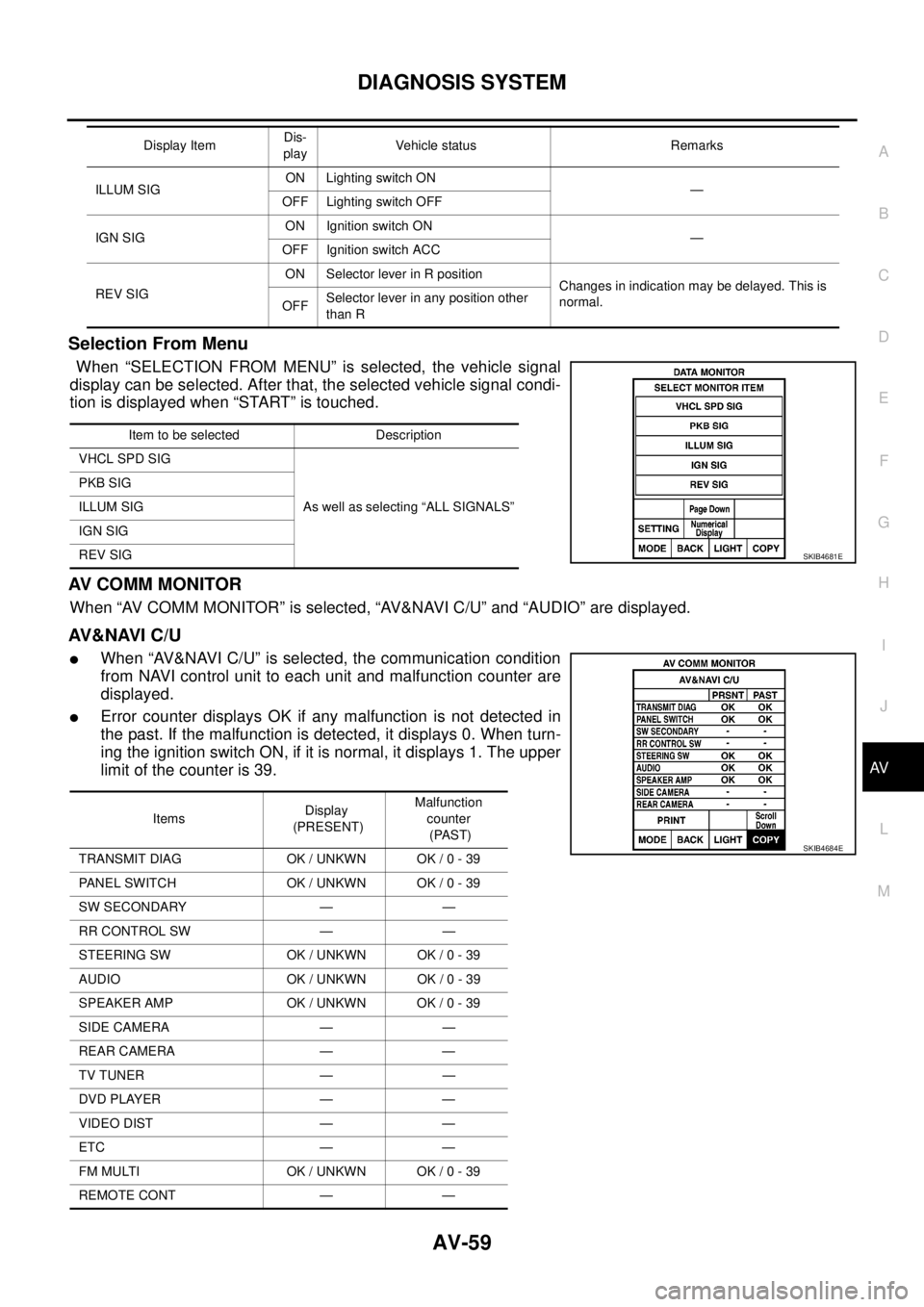
Selection From Menu
When “SELECTION FROM MENU” is selected, the vehicle signal
display can be selected. After that, the selected vehicle signal condi-
tion is displayed when “START” is touched.
AV C O M M M O N I T O R
When “AV COMM MONITOR” is selected, “AV&NAVI C/U” and “AUDIO” are displayed.
AV&NAVI C/U
lWhen “AV&NAVI C/U” is selected, the communication condition
from NAVI control unit to each unit and malfunction counter are
displayed.
lError counter displays OK if any malfunction is not detected in
the past. If the malfunction is detected, it displays 0. When turn-
ing the ignition switch ON, if it is normal, it displays 1. The upper
limitofthecounteris39.
ILLUM SIGON Lighting switch ON
—
OFF Lighting switch OFF
IGN SIGON Ignition switch ON
—
OFF Ignition switch ACC
REV SIGON Selector lever in R position
Changes in indication may be delayed. This is
normal.
OFFSelector lever in any position other
than R Display ItemDis-
playVehicle status Remarks
Item to be selected Description
VHCL SPD SIG
As well as selecting “ALL SIGNALS” PKB SIG
ILLUM SIG
IGN SIG
REV SIG
SKIB4681E
ItemsDisplay
(PRESENT)Malfunction
counter
(PAST)
TRANSMIT DIAG OK / UNKWN OK / 0 - 39
PANEL SWITCH OK / UNKWN OK / 0 - 39
SW SECONDARY — —
RR CONTROL SW — —
STEERING SW OK / UNKWN OK / 0 - 39
AUDIO OK / UNKWN OK / 0 - 39
SPEAKER AMP OK / UNKWN OK / 0 - 39
SIDE CAMERA — —
REAR CAMERA — —
TV TUNER — —
DVD PLAYER — —
VIDEO DIST — —
ETC — —
FM MULTI OK / UNKWN OK / 0 - 39
REMOTE CONT — —
SKIB4684E
Page 607 of 3171

POWERDOORLOCKSYSTEM
BL-23
C
D
E
F
G
H
J
K
L
MA
B
BL
System DescriptionEIS00D7R
Power is supplied at all times
lthrough 50A fusible link (letterG, located in the fuse and fusible link box)
lto BCM terminal 57
lthrough 10A fuse [No. 21, located in the fuse block (J/B)]
lto BCM terminal 41
lthrough 10A fuse [No. 22, located in the fuse block (J/B)]
lto key switch terminal 2.
When key switch is ON, power is supplied
lthrough key switch terminal 1
lto BCM terminal 5.
When ignition switch is in ON or START position
lthrough 10A fuse [No. 1, located in the fuse block (J/B)]
lto BCM terminal 3.
Ground is supplied
lto BCM terminal 55
lthrough body grounds M21, M80 and M83.
Door switch operation
When front door switch (driver side) is ON (door is OPEN), ground is supplied
lto BCM terminal 15
lthrough front door switch (driver side) terminal 2
lthrough front door switch (driver side) case ground.
When front door switch (passenger side) is ON (door is OPEN), ground is supplied
lto BCM terminal 14
lthrough front door switch (passenger side) terminal 2
lthrough front door switch (passenger side) case ground.
When rear door switch LH is ON (door is OPEN), ground is supplied (Double cab model)
lto BCM terminal 16
lthrough rear door switch LH terminal 2
lthrough rear door switch LH case ground.
When rear door switch RH is ON (door is OPEN), ground is supplied (Double cab model)
lto BCM terminal 12
lthrough rear door switch RH terminal 2
lthrough rear door switch RH case ground.
Key cylinder switch operation (Without multi-remote control system)
When key cylinder is turned to lock position, ground is supplied
lthrough BCM terminal 34
lto key cylinder switch (driver and passenger side) terminals 4
lthrough key cylinder switch (driver and passenger side) terminals 5
lthrough body ground M21, M80 and M83
then all doors are locked.
When key cylinder is turned to unlock position, ground is supplied
lthrough BCM terminal 32
lto key cylinder switch (driver and passenger side) terminal 6
lthrough key cylinder switch (driver and passenger side) terminal 5
lthrough body ground M21, M80 and M83
then all doors are unlocked.
Power door lock operation with door lock/unlock switch
When doors are lock by door lock/unlock switch, ground is supplied
Page 675 of 3171

MULTI-REMOTE CONTROL SYSTEM
BL-91
C
D
E
F
G
H
J
K
L
MA
B
BL
System DescriptionEIS00DBE
INPUTS
Power is supplied at all times
lto BCM terminal 57
lthrough 50A fusible link (letterG, located in the fuse and fusible link box).
lto BCM terminal 41
lthrough 10A fuse [No. 21, located in the fuse block (J/B)].
When the key switch is ON (key is inserted in ignition key cylinder), power is supplied
lto BCM terminal 5
lthrough key switch terminals 2 and 1
lthrough 10A fuse [No. 22, located in the fuse block (J/B)].
When the ignition switch is ACC or ON, power is supplied
lto BCM terminal 4
lthrough 10A fuse [No. 4, located in the fuse block (J/B)].
When the ignition switch is ON or START, power is supplied
lto BCM terminal 3
lthrough 10A fuse [No. 1, located in the fuse block (J/B)].
When the front door switch (driver side) is ON (door is OPEN), ground is supplied
lto BCM terminal 15
lthrough front door switch (driver side) terminal 2
lto front door switch (driver side) case ground.
When the front door switch (passenger side) is ON (door is OPEN), ground is supplied
lto BCM terminal 14
lthrough front door switch (passenger side) terminal 2
lto front door switch (passenger side) case ground.
When the rear door switch LH is ON (door is OPEN), ground is supplied
lto BCM terminal 16
lthrough rear door switch LH terminal 2
lto rear door switch LH case ground.
When the rear door switch RH is ON (door is OPEN), ground is supplied
lto BCM terminal 12
lthrough rear door switch RH terminal 2
lto rear door switch RH case ground.
The multi-remote control system controls operation of the
lpowerdoorlock
linterior lamp and ignition keyhole illumination
lhazard reminder
lauto door lock operation
OPERATING PROCEDURE
Power Door Lock Operation
BCM receives a LOCK signal from keyfob. BCM locks all doors with input of LOCK signal from keyfob.
When an UNLOCK signal is sent from keyfob once, driver's door is unlocked.
Then, if an UNLOCK signal is sent from keyfob again within 5 seconds, all doors are unlocked.
Hazard Reminder
When the doors are locked or unlocked by keyfob, power is supplied to hazard warning lamp.
Hazard reminder does not operate if any door switches are ON (any doors are OPEN).
How to change hazard and horn reminder mode
Hazard and horn reminder can be changed using “WORK SUPPORT” mode in “MULTI ANSWER BACK SET”.
Refer toBL-102, "
CONSULT-II Function (BCM)".
Page 685 of 3171

MULTI-REMOTE CONTROL SYSTEM
BL-101
C
D
E
F
G
H
J
K
L
MA
B
BL
Terminals and Reference Value for BCMEIS00DBI
*: Double cab modelsTerminalWire
ColorItem ConditionVoltage (V)
(Approx.)
3 Y Ignition switch ON or START Ignition switch ON or START Battery voltage
4 V Ignition switch ACC or ON Ignition switch ACC or ON Battery voltage
5RKeyswitchON (Key is inserted in key cylinder) Battery voltage
OFF (Key is removed from key cylinder) 0
12* L Rear door switch RHON (door open) 0
OFF (door closed) Battery voltage
14 LGFront door switch
(Passenger side)ON (door open) 0
OFF (door closed) Battery voltage
15 SBFront door switch
(Driver side)ON (door open) 0
OFF (door closed) Battery voltage
16* P Rear door switch LHON (door open) 0
OFF (door closed) Battery voltage
21 P CAN L — —
22 L CAN H — —
41 Y Power source (Fuse) — Battery voltage
55 B Ground — 0
57 W Power source (Fusible link) — Battery voltage
Page 686 of 3171

BL-102
MULTI-REMOTE CONTROL SYSTEM
CONSULT-II Function (BCM)
EIS00DBJ
CONSULT-II can display each diagnostic item using the diagnostic test modes shown following.
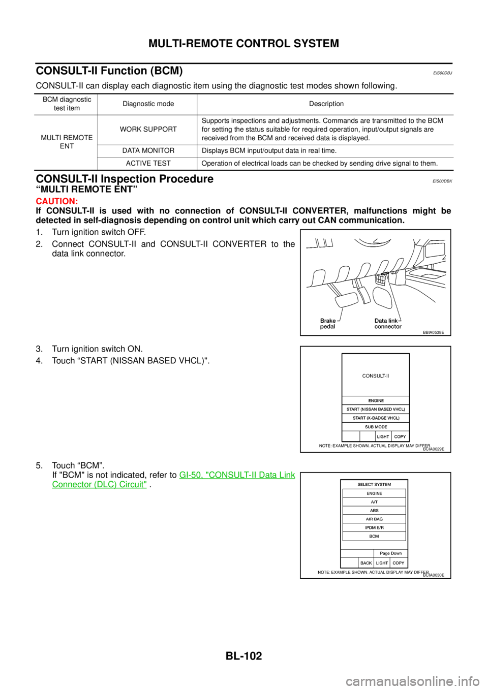
CONSULT-II Inspection ProcedureEIS00DBK
“MULTI REMOTE ENT”
CAUTION:
If CONSULT-II is used with no connection of CONSULT-II CONVERTER, malfunctions might be
detected in self-diagnosis depending on control unit which carry out CAN communication.
1. Turn ignition switch OFF.
2. Connect CONSULT-II and CONSULT-II CONVERTER to the
data link connector.
3. Turn ignition switch ON.
4. Touch “START (NISSAN BASED VHCL)".
5. Touch “BCM”.
If "BCM" is not indicated, refer toGI-50, "
CONSULT-II Data Link
Connector (DLC) Circuit".
BCM diagnostic
test itemDiagnostic mode Description
MULTI REMOTE
ENTWORK SUPPORTSupports inspections and adjustments. Commands are transmitted to the BCM
for setting the status suitable for required operation, input/output signals are
received from the BCM and received data is displayed.
DATA MONITOR Displays BCM input/output data in real time.
ACTIVE TEST Operation of electrical loads can be checked by sending drive signal to them.
BBIA0538E
BCIA0029E
BCIA0030E
Page 699 of 3171

MULTI-REMOTE CONTROL SYSTEM
BL-115
C
D
E
F
G
H
J
K
L
MA
B
BL
ID Code Entry ProcedureEIS00DBU
KEYFOB ID SET UP
NOTE:
Keyfob ID setup procedure is same as ignition key registration (NATS initialization) procedure.
When the registration of the ignition key (NATS initialization) is performed with a NATS program card,
the registration of keyfob ID is done at the same time.
Regarding the procedures of NATS initialization and ignition key ID registration, refer to CONSULT-II
operation manual, NATS.
If additional key or key replacement is demanded, request all registed key fobs to be brought to the
dealer.
During the NATS initialization process, all registered key IDs will be deleted, thus, it is necessary to re-
register all keys.
CONSULT-II INSPECTION PROCEDURE
1. Turn ignition switch OFF.
2. Insert NATS program card into CONSULT-II.
3. Connect CONSULT-II and CONSULT-II CONVERTER to data
link connector.
4. Turn ignition switch ON.
5. Touch “START”.
6. Touch “OTHER”.Program card : NATS (AEN04A-1)
BBIA0538E
PBR455D
PIIB0900E
Page 2280 of 3171

DESCRIPTION
MA-5
C
D
E
F
G
H
I
J
K
MA
B
MA
DESCRIPTIONPFP:00000
Pre-Delivery Inspection ItemsELS001K2
Shown below are Pre-delivery Inspection Items required for the new vehicle. It is recommended that
necessary items other than those listed here be added, paying due regard to the conditions in each
country.
Perform applicable items on each model. Consult text of this section for specifications.
Install vehicle protection kit
Fit all accessories ordered (if applicable) (e.g. towbar, audio, navigation, air conditioner, styling kit)
UNDER HOOD — engine off
Check coolant level and cooling system for leaks
Charge battery and check terminals for condition
Check drive belts tension
Check fuel filter for water or dust (diesel only) and fuel system for leaks
Check engine oil level and for oil leaks
Check brake and clutch fluid levels and fluid lines for leaks
Check and top up washer reservoirs
Check power steering fluid level and fluid lines for leaks (if applicable)
Check air conditioning system for gas leaks (if applicable)
ON INSIDE AND OUTSIDE
Install transit fuse if removed for vehicle storage
Check instruments, gauges, lamps, horn and accessories for operation
Check wipers and washers for operation and adjustment
Check interior and door mirrors and sun visors for operation
Set radio code and set clock
Check parking brake adjustment
Check clutch pedal adjustment
Check steering lock operation
Check seat adjusters and seat belts for operation
Check all windows for operation and alignment
Check mouldings, trim and fittings for fit and alignment
Check weatherstrips for fit and adhesion
Check hood, trunk lid, door panels and fuel lid for fit and alignment
Check latches, keys, remote key, door locks and remote trunk lid and fuel lid release for operation
Check wheel nut torques
Check tyre pressure (incl. spare tyre)
Check tool kit and jack for operation
Check automatic transmission/transaxle starter inhibitor (if applicable)
Check sunroof for operation and alignment (if applicable)
UNDER BODY
Check manual transmission/transaxle, differential and transfer box for oil level and oil leaks
Tighten bolts and nuts steering linkage and gear box, axle/suspension parts, propeller and exhaust system
Check brake and clutch lines, and oil/fluid reservoirs for leaks
Remove front suspension spacer blocks (if applicable)
Check body mounting torque (if applicable)
Page 2598 of 3171

HARNESS
PG-69
C
D
E
F
G
H
I
J
L
MA
B
PG
FTS EC Fuel Pump Temperature Sensor
GLOW EC Glow Control System
H/AIM LT Headlamp Aiming Control System
H/LAMP LT Headlamp
HEATUP EC Heat Up Switch
HLC WW Headlamp Washer
HORN WW Horn
HSEAT SE Heated Seat
I/KEY BL Intelligent Key System
I/MIRR GW Inside Mirror (Auto Anti-dazzling Mirror)
IATS EC Intake Air Temperature Sensor
ILL LT Illumination
INJ/PW EC Fuel Injector Power Supply
INJECT EC Fuel Injector
INT/L LT Room and Map Lamps
INT/V EC Intake Air Control Valve Control Solenoid Valve
MAFS EC Mass Air Flow Sensor
MAIN AT Main Power Supply and Ground Circuit
MAIN EC Main Power Supply and Ground Circuit
METER DI Speedometer, Tachometer, Temp. and Fuel Gauges
MIL/DL EC Malfunction Indicator Lamp, Data Link Connector
MIRROR GW Door Mirror
MMSW AT Manual Mode Switch
MULTI BL Multi-remote Control System
NATS BL NATS (Nissan Anti-Theft System)
NAVI AV Navigation System
NONDTC AT NON-detective Items
P/SCKT WW Power Socket
PHONE AV Telephone
PNP/SW AT Park/Neutral Position Switch
PNP/SW EC Park/Neutral Position Switch
POWER PG Power Supply Routing
R/FOG LT Rear Fog Lamp
RP/SEN EC Refrigerant Pressure Sensor
S/LOCK BL Power Door Lock — Super Lock
S/SIG EC Start Signal
SEAT SE Power Seat
SHIFT AT A/T Shift Lock System
SROOF RF Sunroof
SRS SRS Supplemental Restraint System
START SC Starting System
STOP/L LT Stop Lamp
STSIG AT Start Signal Circuit
T/F TF TransferCode Section Wiring Diagram Name