under cover NISSAN NOTE 2016 Service Owner's Guide
[x] Cancel search | Manufacturer: NISSAN, Model Year: 2016, Model line: NOTE, Model: NISSAN NOTE 2016Pages: 3641, PDF Size: 28.72 MB
Page 2161 of 3641
INT-10
< SYMPTOM DIAGNOSIS >
SQUEAK AND RATTLE TROUBLE DIAGNOSES
If possible, drive the vehicle with the customer until the noise is duplicated. Note any additional information on
the Diagnostic Worksheet regarding the conditions or lo cation of the noise. This information can be used to
duplicate the same conditions when you confirm the repair.
If the noise can be duplicated easily during the test drive, to help identify the source of the noise, try to dupli-
cate the noise with the vehicle stopped by doing one or all of the following:
1) Close a door.
2) Tap or push/pull around the area where the noise appears to be coming from.
3) Rev the engine.
4) Use a floor jack to recreate vehicle “twist”.
5) At idle, apply engine load (electrical load, half-clutch on M/T model, drive position on CVT and A/T models).
6) Raise the vehicle on a hoist and hit a tire with a rubber hammer.
• Drive the vehicle and attempt to duplicate the conditions the customer states exist when the noise occurs.
• If it is difficult to duplicate the noise, drive the v ehicle slowly on an undulating or rough road to stress the
vehicle body.
CHECK RELATED SERVICE BULLETINS
After verifying the customer concern or symptom, chec k ASIST for Technical Service Bulletins (TSBs) related
to that concern or symptom.
If a TSB relates to the symptom, follo w the procedure to repair the noise.
LOCATE THE NOISE AND IDENTIFY THE ROOT CAUSE
1. Narrow down the noise to a general area. To help pi npoint the source of the noise, use a listening tool
(Chassis Ear: J-39570, Engine Ear: J-39565 and mechanic's stethoscope).
2. Narrow down the noise to a more specific area and identify the cause of the noise by: • removing the components in the area that you suspect the noise is coming from.Do not use too much force when removing clips and fasteners, otherwise clips and fasteners can be
broken or lost during the repair, resulting in the creation of new noise.
• tapping or pushing/pulling the component that you suspect is causing the noise. Do not tap or push/pull the component with excessive force, otherwise the noise will be eliminated only
temporarily.
• feeling for a vibration with your hand by touching the component(s) that you suspec t is (are) causing the
noise.
• placing a piece of paper between components that you suspect are causing the noise.
• looking for loose components and contact marks.
Refer to INT-10, "
Generic Squeak and Rattle Troubleshooting".
REPAIR THE CAUSE
• If the cause is a loose component, tighten the component securely.
• If the cause is insufficient clearance between components:
- separate components by repositioning or loos ening and retightening the component, if possible.
- insulate components with a suitable insulator such as urethane pads, foam blocks, felt cloth tape or urethane tape. A NISSAN Squeak and Rattle Kit (J-50397) is av ailable through your authorized NISSAN Parts Depart-
ment.
CAUTION:
Do not use excessive force as many components are constructed of plastic and may be damaged.
NOTE:
• Always check with the Parts Department for the latest parts information.
• The materials contained in the NISSAN Squeak and Rattle Kit (J-50397) are listed on the inside cover of the
kit; and can each be ordered separately as needed.
• The following materials not found in the kit can also be used to repair squeaks and rattles.
- SILICONE GREASE: Use instead of UHMW tape that will be visible or does not fit. The silicone grease will only last a few months.
- SILICONE SPRAY: Use when grease cannot be applied.
- DUCT TAPE: Use to eliminate movement.
CONFIRM THE REPAIR
Confirm that the cause of a noise is repaired by test driving the vehicle. Operate the vehicle under the same
conditions as when the noise originally occurred. Refer to the notes on the Diagnostic Worksheet.
Generic Squeak and Rattle TroubleshootingINFOID:0000000012431858
Refer to Table of Contents for specific component removal and installation information.
Revision: August 2015 2016 Versa Note
cardiagn.com
Page 2324 of 3641
PERIODIC MAINTENANCEMA-9
< PERIODIC MAINTENANCE >
C
DE
F
G H
I
J
K L
M B
MA
N
O A
NOTE:
•
Maintenance items with “ ” shoul d be performed more frequently according to “Maintenance Under Severe Driving Condi-
tions”.
• (1) Use only Genuine NISSAN CVT fluid. If towing a trailer, using a camper or a car-top carrier, of driving on rough or muddy roads,
inspect CVT fluid deterioration at NISSAN dealers every 60,000 miles (96,000 km), then change CVT fluid if necessary. And if th e
inspection is not performed, change (not just inspect) CVT fluid every 60,000 miles (96,000 km). Using transmission fluid other than
Genuine NISSAN CVT fluid will damage the CVT, which is not covered by the NISSAN new vehicle limited warranty.
• (2) If tower a trailer, using a camper or car-top carrier, or driving on rough or muddy roads, change (not just inspect) oil a t every 20,000
miles (32,000 km) or 24 months.
• (3) Refer to "Tire rotation" under "GENERAL MAINTENANCE" heading earlier in this section.
MAINTENANCE UNDER SEVERE DRIVING CONDITIONS
The maintenance intervals shown on the preceding pages are for normal operating conditions. If the vehicle is
mainly operated under severe driving conditions as shown below, more frequent maintenance must be per-
formed on the following items as shown in the table.
Severe driving conditions
• Repeated short trips of less than 5 miles (8 km).
• Repeated short trips of less than 10 miles (16 km) wi th outside temperatures remaining below freezing.
• Operating in hot weather in stop-and-go "rush hour" traffic.
Brake fluid RR
C VT flu id NO TE (1)IIIII
M anu al t ra nsa xle o il NO TE (2)IIIII
Steering gear and linkage, axle and sus-
pension parts II
Tire rotation NOTE (3)
Drive shaft boots IIIII
Exhaust system II
In-cabin microfilter RRR
Intelligent key battery RRR
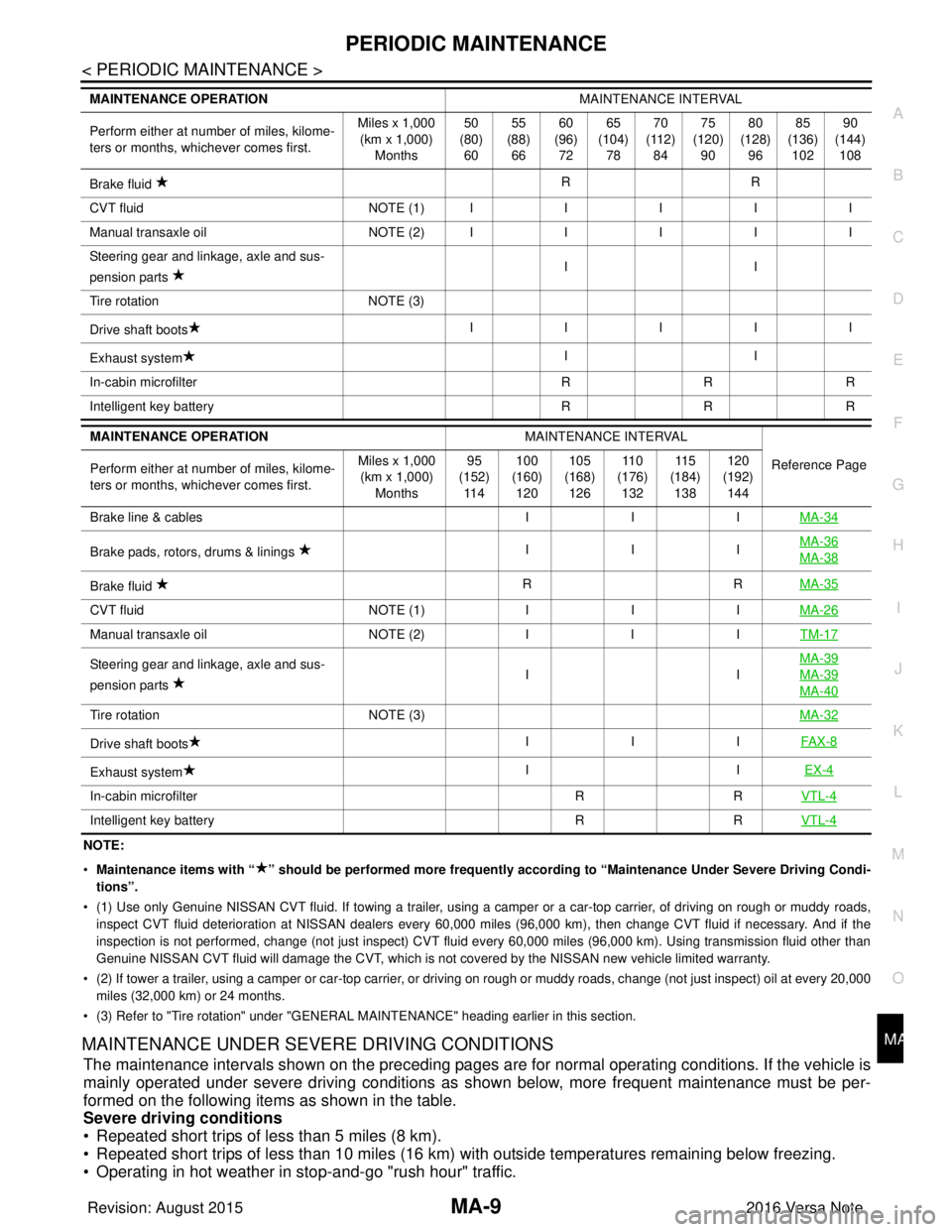
MAINTENANCE OPERATION MAINTENANCE INTERVAL
Reference Page
Perform either at number of miles, kilome-
ters or months, whichever comes first. Miles x 1,000
(km x 1,000) Months 95
(152) 11 4 100
(160) 120 105
(168) 126 11 0
(176) 132 11 5
(184) 138 120
(192) 144
Brake line & cables IIIMA-34
Brake pads, rotors, drums & linings IIIMA-36MA-38
Brake fluid
RR
MA-35
CVT fluid NOTE (1)IIIMA-26
Manual transaxle oil NOTE (2)IIITM-17
Steering gear and linkage, axle and sus-
pension parts IIMA-39MA-39
MA-40
Tire rotation
NOTE (3) MA-32
Drive shaft boots III
FAX-8
Exhaust system II
EX-4
In-cabin microfilter RRVTL-4
Intelligent key battery RRVTL-4
MAINTENANCE OPERATION MAINTENANCE INTERVAL
Perform either at number of miles, kilome-
ters or months, whichever comes first. Miles x 1,000
(km x 1,000)
Months 50
(80)
60 55
(88)
66 60
(96)
72 65
(104)
78 70
(112)
84 75
(120)
90 80
(128)
96 85
(136)
102 90
(144)
108
Revision: August 2015 2016 Versa Note
cardiagn.com
Page 2328 of 3641
ENGINE MAINTENANCEMA-13
< PERIODIC MAINTENANCE >
C
DE
F
G H
I
J
K L
M B
MA
N
O A
ENGINE MAINTENANCE
DRIVE BELT
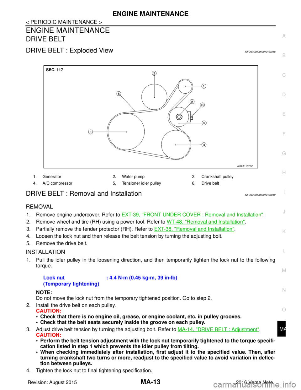
DRIVE BELT : Exploded ViewINFOID:0000000012432248
DRIVE BELT : Removal and InstallationINFOID:0000000012432249
REMOVAL
1. Remove engine undercover. Refer to
EXT-39, "FRONT UNDER COVER : Removal and Installation".
2. Remove wheel and tire (RH) using a power tool. Refer to WT-48, "
Removal and Installation".
3. Partially remove the fender protector (RH). Refer to EXT-38, "
Removal and Installation".
4. Loosen the lock nut and then release the belt tension by turning the adjusting bolt.
5. Remove the drive belt.
INSTALLATION
1. Pull the idler pulley in the loosening direction, and then temporarily tighten the lock nut to the following
torque.
NOTE:
Do not move the lock nut from the temporary tightened position. Go to step 2.
2. Install the drive belt on each pulley. CAUTION:
• Check that there is no engine oil, grease, or engine coolant, etc. in pulley grooves.
• Check that the belt seats securely inside the groove on each pulley.
3. Adjust drive belt tension by turning the adjusting bolt. Refer to MA-14, "
DRIVE BELT : Adjustment".
CAUTION:
• Perform the belt tension adjustment with the lock nut temporarily tightened to the torque specifi-
cation listed in step 1 which preven ts the idler pulley from tilting.
• When checking immediately after in stallation, first adjust it to the specified value. Then, after
turning crankshaft two turns or more, readjust to the specified value to avoid variation in deflec-
tion between pulleys.
4. Tighten the lock nut to final tightening specification.
1. Generator 2. Water pump3. Crankshaft pulley
4. A/C compressor 5. Tensioner idler pulley6. Drive belt
ALBIA1157ZZ
Lock nut
(Temporary tightening): 4.4 N·m (0.45 kg-m, 39 in-lb)
Revision: August 2015
2016 Versa Note
cardiagn.com
Page 2331 of 3641
MA-16
< PERIODIC MAINTENANCE >
ENGINE MAINTENANCE
ENGINE COOLANT : Draining Engine Coolant
INFOID:0000000012432253
WARNING:
Do not remove the radiator cap when the engine is hot. Serious burns could occur from high-pressure
engine coolant escaping from the radiator. Wrap a th ick cloth around the cap. Slowly push down and
turn it a quarter turn to allow built-up pressure to escape. Carefully remove the cap by pushing it down
and turning it all the way.
1. Remove front under cover. Refer to EXT-39, "
FRONT UNDER COVER : Removal and Installation".
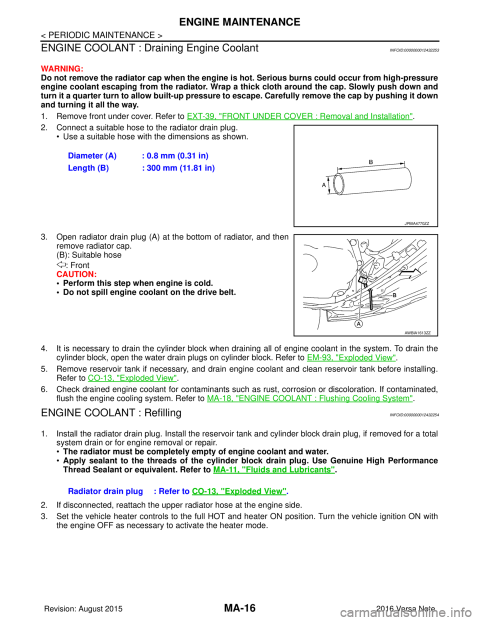
2. Connect a suitable hose to the radiator drain plug. • Use a suitable hose with the dimensions as shown.
3. Open radiator drain plug (A) at the bottom of radiator, and then remove radiator cap.
(B): Suitable hose
: Front
CAUTION:
• Perform this step when engine is cold.
• Do not spill engine coolant on the drive belt.
4. It is necessary to drain the cylinder block when drai ning all of engine coolant in the system. To drain the
cylinder block, open the water drain plugs on cylinder block. Refer to EM-93, "
Exploded View".
5. Remove reservoir tank if necessary, and drain engine coolant and clean reservoir tank before installing. Refer to CO-13, "
Exploded View".
6. Check drained engine coolant for contaminants such as rust, corrosion or discoloration. If contaminated, flush the engine cooling system. Refer to MA-18, "
ENGINE COOLANT : Flushing Cooling System".
ENGINE COOLANT : RefillingINFOID:0000000012432254
1. Install the radiator drain plug. Install the reservoir tank and cylinder block drain plug, if removed for a total
system drain or for engine removal or repair.
• The radiator must be completely empty of engine coolant and water.
• Apply sealant to the threads of the cylinder block drain plug. Use Genuine High Performance
Thread Sealant or equivalent. Refer to MA-11, "
Fluids and Lubricants".
2. If disconnected, reattach the upper radiator hose at the engine side.
3. Set the vehicle heater controls to the full HOT and heat er ON position. Turn the vehicle ignition ON with
the engine OFF as necessary to activate the heater mode. Diameter (A) : 0.8 mm (0.31 in)
Length (B) : 300 mm (11.81 in)
JPBIA4770ZZ
AWBIA1613ZZ
Radiator drain plug : Refer to
CO-13, "Exploded View".
Revision: August 2015 2016 Versa Note
cardiagn.com
Page 2332 of 3641
ENGINE MAINTENANCEMA-17
< PERIODIC MAINTENANCE >
C
DE
F
G H
I
J
K L
M B
MA
N
O A
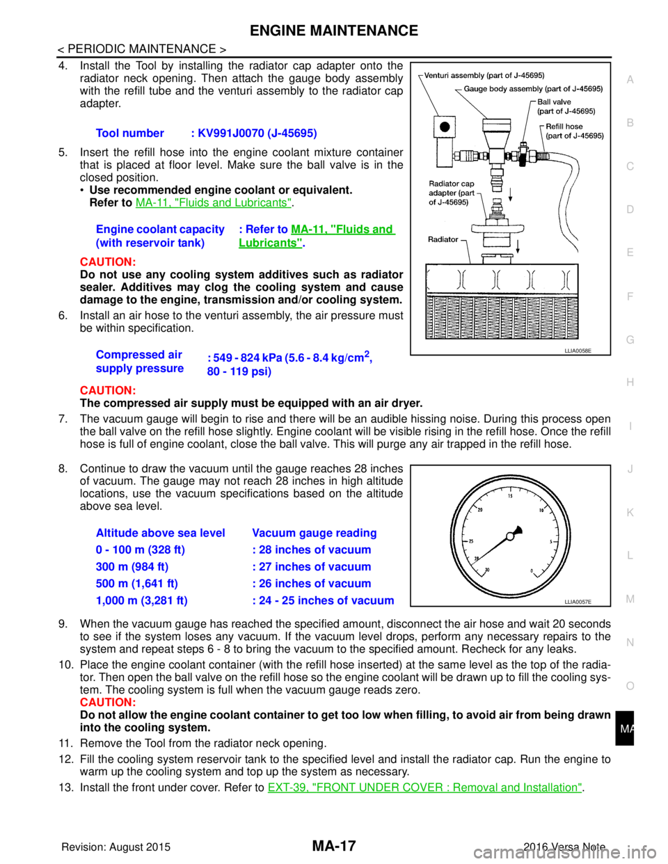
4. Install the Tool by installing the radiator cap adapter onto the
radiator neck opening. Then attach the gauge body assembly
with the refill tube and the venturi assembly to the radiator cap
adapter.
5. Insert the refill hose into the engine coolant mixture container that is placed at floor level. Make sure the ball valve is in the
closed position.
•Use recommended engine coolant or equivalent.
Refer to MA-11, "
Fluids and Lubricants".
CAUTION:
Do not use any cooling system additives such as radiator
sealer. Additives may clog the cooling system and cause
damage to the engine, transmission and/or cooling system.
6. Install an air hose to the venturi assembly, the air pressure must be within specification.
CAUTION:
The compressed air supply must be equipped with an air dryer.
7. The vacuum gauge will begin to rise and there will be an audible hissing noise. During this process open the ball valve on the refill hose slightly. Engine coolant will be visible rising in the refill hose. Once the refill
hose is full of engine coolant, close the ball valve. This will purge any air trapped in the refill hose.
8. Continue to draw the vacuum until the gauge reaches 28 inches of vacuum. The gauge may not reach 28 inches in high altitude
locations, use the vacuum specifications based on the altitude
above sea level.
9. When the vacuum gauge has reached the specified amount, disconnect the air hose and wait 20 seconds
to see if the system loses any vacuum. If the vacuum level drops, perform any necessary repairs to the
system and repeat steps 6 - 8 to br ing the vacuum to the specified amount. Recheck for any leaks.
10. Place the engine coolant container (with the refill hose in serted) at the same level as the top of the radia-
tor. Then open the ball valve on the refill hose so the engine coolant will be drawn up to fill the cooling sys-
tem. The cooling system is full when the vacuum gauge reads zero.
CAUTION:
Do not allow the engine coolant co ntainer to get too low when filling, to avoid air from being drawn
into the cooling system.
11. Remove the Tool from the radiator neck opening.
12. Fill the cooling system reservoir tank to the specif ied level and install the radiator cap. Run the engine to
warm up the cooling system and top up the system as necessary.
13. Install the front under cover. Refer to EXT-39, "
FRONT UNDER COVER : Removal and Installation".
Tool number : KV991J0070 (J-45695)
Engine coolant capacity
(with reservoir tank)
: Refer to
MA-11, "
Fluids and
Lubricants".
Compressed air
supply pressure : 549 - 824 kPa (5.6 - 8.4 kg/cm
2,
80 - 119 psi)LLIA0058E
Altitude above sea level Vacuum gauge reading
0 - 100 m (328 ft) : 28 inches of vacuum
300 m (984 ft) : 27 inches of vacuum
500 m (1,641 ft) : 26 inches of vacuum
1,000 m (3,281 ft) : 24 - 25 inches of vacuum
LLIA0057E
Revision: August 2015 2016 Versa Note
cardiagn.com
Page 2343 of 3641
MA-28
< PERIODIC MAINTENANCE >
CHASSIS AND BODY MAINTENANCE
29. When the flow of CVT fluid slows to a drip, tighten the drain plug to the specified torque. TM-242,
"Removal and Installation".
CAUTION:
Never reuse drain plug gasket.
30. Lift down the vehicle.
31. Select “Work Support” in “TRANSMISSION” using CONSULT.
32. Select “CONFORM CVTF DETERIORTN”.
33. Select “Erase”.
34. Stop the engine.
CVT FLUID : AdjustmentINFOID:0000000012432269
CAUTION:
• Use only Genuine NISSAN CVT Fluid NS-3. Using transmission fluid other than Genuine NISSAN
CVT Fluid NS-3 will damage the CVT, which is not covered by the (NISSAN new vehicle limited) war-
ranty.
• During adjustment of the CVT fluid level, check CO NSULT so that the oil temperature may be main-
tained from 35 to 45 °C (95 to 113 °F).
• Use caution when looking into the drain hole as th ere is a risk of dripping fluid entering the eye.
1. Check that the selector lever is in the “P ” position, then completely engage the parking brake.
2. Start the engine.
3. Adjust the CVT fluid temperature to be approximately 40 °C (104° F).
NOTE:
The CVT fluid is largely affected by temperature. Therefore be sure to use CONSULT and check the
“FLUID TEMP” under “TRANSMISSION” in “Data Monitor” while adjusting.
4. While depressing the brake pedal, shift the selector lever to the entire position from “P” to “L”, and shift it to the “P” position.
NOTE:
Hold the lever at each position for 5 seconds.
5. Lift up the vehicle.
6. Check that there is no CVT fluid leakage.
7. Remove the drain plug. Refer to TM-242, "
Removal and Installation".
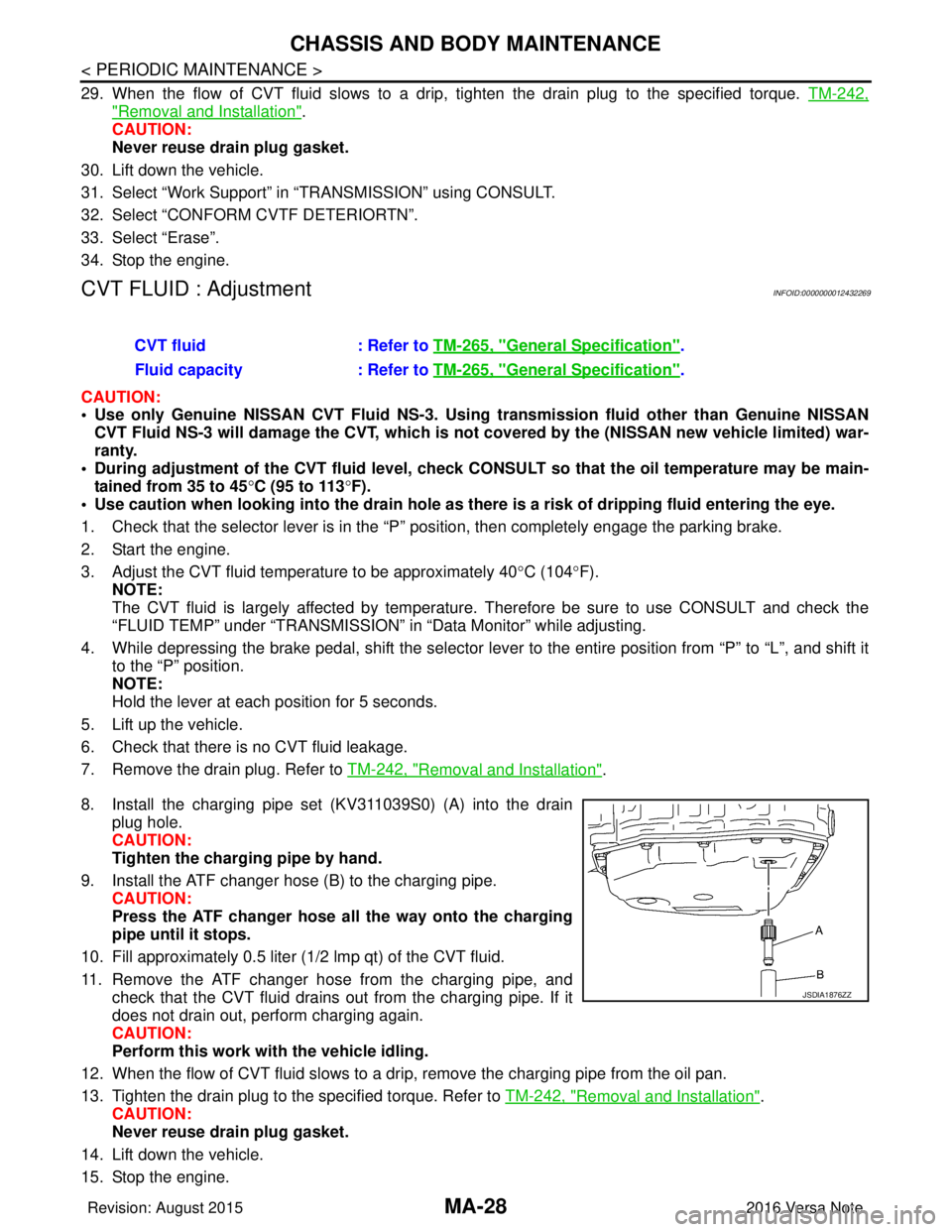
8. Install the charging pipe set (KV311039S0) (A) into the drain plug hole.
CAUTION:
Tighten the charging pipe by hand.
9. Install the ATF changer hose (B) to the charging pipe. CAUTION:
Press the ATF changer hose all the way onto the charging
pipe until it stops.
10. Fill approximately 0.5 liter (1/2 lmp qt) of the CVT fluid.
11. Remove the ATF changer hose from the charging pipe, and check that the CVT fluid drains out from the charging pipe. If it
does not drain out, perform charging again.
CAUTION:
Perform this work with the vehicle idling.
12. When the flow of CVT fluid slows to a drip, remove the charging pipe from the oil pan.
13. Tighten the drain plug to the specified torque. Refer to TM-242, "
Removal and Installation".
CAUTION:
Never reuse drain plug gasket.
14. Lift down the vehicle.
15. Stop the engine. CVT fluid
: Refer to TM-265, "
General Specification".
Fluid capacity : Refer to TM-265, "
General Specification".
JSDIA1876ZZ
Revision: August 2015 2016 Versa Note
cardiagn.com
Page 2483 of 3641
SQUEAK AND RATTLE TROUBLE DIAGNOSESMIR-9
< SYMPTOM DIAGNOSIS >
C
DE
F
G H
I
J
K
M A
B
MIR
N
O P
If possible, drive the vehicle with the customer until the noise is duplicated. Note any additional information on
the Diagnostic Worksheet regarding the conditions or lo cation of the noise. This information can be used to
duplicate the same conditions when you confirm the repair.
If the noise can be duplicated easily during the test drive, to help identify the source of the noise, try to dupli-
cate the noise with the vehicle stopped by doing one or all of the following:
1) Close a door.
2) Tap or push/pull around the area where the noise appears to be coming from.
3) Rev the engine.
4) Use a floor jack to recreate vehicle “twist”.
5) At idle, apply engine load (electrical load, half-clutch on M/T model, drive position on CVT and A/T models).
6) Raise the vehicle on a hoist and hit a tire with a rubber hammer.
• Drive the vehicle and attempt to duplicate the conditions the customer states exist when the noise occurs.
• If it is difficult to duplicate the noise, drive the vehicle slowly on an undulating or rough road to stress the
vehicle body.
CHECK RELATED SERVICE BULLETINS
After verifying the customer concern or symptom, check ASIST for Technical Service Bulletins (TSBs) related
to that concern or symptom.
If a TSB relates to the symptom, follow the procedure to repair the noise.
LOCATE THE NOISE AND IDENTIFY THE ROOT CAUSE
1. Narrow down the noise to a general area. To help pinpoint the source of the noise, use a listening tool (Chassis Ear: J-39570, Engine Ear: J-39565 and mechanic's stethoscope).
2. Narrow down the noise to a more specific area and identify the cause of the noise by: • removing the components in the area that you suspect the noise is coming from.Do not use too much force when removing clips and fasteners, otherwise clips and fasteners can be
broken or lost during the repair, resulting in the creation of new noise.
• tapping or pushing/pulling the component that you suspect is causing the noise.
Do not tap or push/pull the component with excessive force, otherwise the noise will be eliminated only
temporarily.
• feeling for a vibration with your hand by touching the component(s) that you suspect is (are) causing the
noise.
• placing a piece of paper between components that you suspect are causing the noise.
• looking for loose components and contact marks. Refer to MIR-9, "
Generic Squeak and Rattle Troubleshooting".
REPAIR THE CAUSE
• If the cause is a loose component, tighten the component securely.
• If the cause is insufficient clearance between components:
- separate components by repositioning or loos ening and retightening the component, if possible.
- insulate components with a suitable insulator such as urethane pads, foam blocks, felt cloth tape or urethane tape. A NISSAN Squeak and Rattle Kit (J-50397) is available through your authorized NISSAN Parts Depart-
ment.
CAUTION:
Do not use excessive force as many components are constructed of plastic and may be damaged.
NOTE:
• Always check with the Parts Department for the latest parts information.
• The materials contained in the NISSAN Squeak and Rattle Kit (J-50397) are listed on the inside cover of the
kit; and can each be ordered separately as needed.
• The following materials not found in the kit can also be used to repair squeaks and rattles.
- SILICONE GREASE: Use instead of UHMW tape that will be visible or does not fit. The silicone grease will
only last a few months.
- SILICONE SPRAY: Use when grease cannot be applied.
- DUCT TAPE: Use to eliminate movement.
CONFIRM THE REPAIR
Confirm that the cause of a noise is repaired by test driving the vehicle. Operate the vehicle under the same
conditions as when the noise originally occurred. Refer to the notes on the Diagnostic Worksheet.
Generic Squeak and Rattle TroubleshootingINFOID:0000000012432087
Refer to Table of Contents for specific component removal and installation information.
Revision: August 2015 2016 Versa Note
cardiagn.com
Page 2736 of 3641
RSU-8
< REMOVAL AND INSTALLATION >
REAR SHOCK ABSORBER
REMOVAL AND INSTALLATION
REAR SHOCK ABSORBER
Exploded ViewINFOID:0000000012431923
Removal and InstallationINFOID:0000000012431924
REMOVAL
1. Remove the rear shock absorber mask. Refer to INT-33, "Exploded View".
2. Remove the cap from the rear shock absorber.
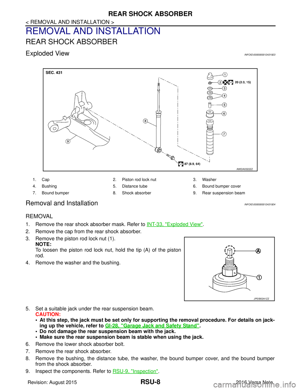
3. Remove the piston rod lock nut (1). NOTE:
To loosen the piston rod lock nut, hold the tip (A) of the piston
rod.
4. Remove the washer and the bushing.
5. Set a suitable jack under the rear suspension beam. CAUTION:
• At this step, the jack must be set only for supp orting the removal procedure. For details on jack-
ing up the vehicle, refer to GI-28, "
Garage Jack and Safety Stand".
• Do not damage the rear suspension beam with the jack.
• Make sure the rear suspension beam is stable when using the jack.
6. Remove the lower shock absorber bolt.
7. Remove the rear shock absorber.
8. Remove the bushing, the distance tube, the washer, the bound bumper cover, and the bound bumper
from the shock absorber.
9. Inspect the components. Refer to RSU-9, "
Inspection".
1. Cap 2. Piston rod lock nut 3. Washer
4. Bushing 5. Distance tube6. Bound bumper cover
7. Bound bumper 8. Shock absorber 9. Rear suspension beam
AWEIA0322ZZ
JPEIB0241ZZ
Revision: August 2015 2016 Versa Note
cardiagn.com
Page 2822 of 3641
SQUEAK AND RATTLE TROUBLE DIAGNOSESSE-9
< SYMPTOM DIAGNOSIS >
C
DE
F
G H
I
K L
M A
B
SE
N
O P
If possible, drive the vehicle with the customer until the noise is duplicated. Note any additional information on
the Diagnostic Worksheet regarding the conditions or lo cation of the noise. This information can be used to
duplicate the same conditions when you confirm the repair.
If the noise can be duplicated easily during the test drive, to help identify the source of the noise, try to dupli-
cate the noise with the vehicle stopped by doing one or all of the following:
1) Close a door.
2) Tap or push/pull around the area where the noise appears to be coming from.
3) Rev the engine.
4) Use a floor jack to recreate vehicle “twist”.
5) At idle, apply engine load (electrical load, half-clutch on M/T model, drive position on CVT and A/T models).
6) Raise the vehicle on a hoist and hit a tire with a rubber hammer.
• Drive the vehicle and attempt to duplicate the conditions the customer states exist when the noise occurs.
• If it is difficult to duplicate the noise, drive the vehicle slowly on an undulating or rough road to stress the
vehicle body.
CHECK RELATED SERVICE BULLETINS
After verifying the customer concern or symptom, check ASIST for Technical Service Bulletins (TSBs) related
to that concern or symptom.
If a TSB relates to the symptom, follow the procedure to repair the noise.
LOCATE THE NOISE AND IDENTIFY THE ROOT CAUSE
1. Narrow down the noise to a general area. To help pinpoint the source of the noise, use a listening tool (Chassis Ear: J-39570, Engine Ear: J-39565 and mechanic's stethoscope).
2. Narrow down the noise to a more specific area and identify the cause of the noise by: • removing the components in the area that you suspect the noise is coming from.Do not use too much force when removing clips and fasteners, otherwise clips and fasteners can be
broken or lost during the repair, resulting in the creation of new noise.
• tapping or pushing/pulling the component that you suspect is causing the noise.
Do not tap or push/pull the component with excessive force, otherwise the noise will be eliminated only
temporarily.
• feeling for a vibration with your hand by touching the component(s) that you suspect is (are) causing the
noise.
• placing a piece of paper between components that you suspect are causing the noise.
• looking for loose components and contact marks. Refer to SE-9, "
Generic Squeak and Rattle Troubleshooting".
REPAIR THE CAUSE
• If the cause is a loose component, tighten the component securely.
• If the cause is insufficient clearance between components:
- separate components by repositioning or loos ening and retightening the component, if possible.
- insulate components with a suitable insulator such as urethane pads, foam blocks, felt cloth tape or urethane tape. A NISSAN Squeak and Rattle Kit (J-50397) is available through your authorized NISSAN Parts Depart-
ment.
CAUTION:
Do not use excessive force as many components are constructed of plastic and may be damaged.
NOTE:
• Always check with the Parts Department for the latest parts information.
• The materials contained in the NISSAN Squeak and Rattle Kit (J-50397) are listed on the inside cover of the
kit; and can each be ordered separately as needed.
• The following materials not found in the kit can also be used to repair squeaks and rattles.
- SILICONE GREASE: Use instead of UHMW tape that will be visible or does not fit. The silicone grease will
only last a few months.
- SILICONE SPRAY: Use when grease cannot be applied.
- DUCT TAPE: Use to eliminate movement.
CONFIRM THE REPAIR
Confirm that the cause of a noise is repaired by test driving the vehicle. Operate the vehicle under the same
conditions as when the noise originally occurred. Refer to the notes on the Diagnostic Worksheet.
Generic Squeak and Rattle TroubleshootingINFOID:0000000012432032
Refer to Table of Contents for specific component removal and installation information.
Revision: August 2015 2016 Versa Note
cardiagn.com
Page 3307 of 3641

TM-66
< SYSTEM DESCRIPTION >[CVT: RE0F11A]
COMPONENT PARTS
• The low brake solenoid valve uses the linear solenoid valve [N/L (normal low) type].
NOTE:
• The principle of the linear solenoid valve utilizes the fa ct that the force pressing on the valve spool installed
inside the coil increases nearly in proportion to the current . This allows it to produce a fluid pressure that is
proportional to this pressing force.
• The N/L (normal low) type does not produce hydr aulic control when the coil is not energized.
CVT CONTROL SYSTEM : High Clutch & Reverse Brake Solenoid ValveINFOID:0000000012431001
• The high clutch & reverse brake solenoid valve is installed to control valve.
• The high clutch & reverse brake solenoid valve adjusts the tightening pressure of the high clutch and reverse
brake.
• The high clutch & reverse brake solenoid valve uses the linear solenoid valve [N/H (normal high) type].
NOTE:
• The principle of the linear solenoid valve utilizes the fa ct that the force pressing on the valve spool installed
inside the coil increases nearly in proportion to the current . This allows it to produce a fluid pressure that is
proportional to this pressing force.
• The N/H (normal high) produces hydraulic control when the coil is not energized.
CVT CONTROL SYSTEM : Torque Co nverter Clutch Solenoid ValveINFOID:0000000012431002
• The torque converter clutch solenoid valve is installed to control valve.
• The torque converter clutch solenoid valve controls the torque converter clutch control valve. For information
about the torque converter clutch control valve, refer to TM-73, "
TRANSAXLE : Component Description".
• The torque converter clutch solenoid valve utilizes a linear solenoid valve [N/L (normal low) type].
NOTE:
• The principle of the linear solenoid valve utilizes the fa ct that the force pressing on the valve spool installed
inside the coil increases nearly in proportion to the current . This allows it to produce a fluid pressure that is
proportional to this pressing force.
• The N/L (normal low) type does not produce hydr aulic control when the coil is not energized.
CVT CONTROL SYSTEM : Line Pressure Solenoid ValveINFOID:0000000012431003
• The line pressure solenoid valve is installed to control valve.
• The line pressure solenoid valve controls the pressure regulator valve. For information about the pressure
regulator valve, refer to TM-73, "
TRANSAXLE : Component Description".
• The line pressure solenoid valve uses the linear solenoid valve [N/H (normal high) type]. NOTE:
• The principle of the linear solenoid valve utilizes the fa ct that the force pressing on the valve spool installed
inside the coil increases nearly in proportion to the current . This allows it to produce a fluid pressure that is
proportional to this pressing force.
• The N/H (normal high) produces hydraulic control when the coil is not energized.
CVT CONTROL SYSTEM : G SensorINFOID:0000000012431004
• G sensor is installed to floor under instrument lower cover.
• G sensor detects front/rear G and inclination applied to the vehicle.
• G sensor converts front/rear G and inclination applied to the vehicle to voltage signal. TCM evaluates front/
rear G and inclination angle of the vehicle from the voltage signal.
CVT CONTROL SYSTEM : Ov erdrive Control SwitchINFOID:0000000012431005
• The overdrive control switch is installed to the selector lever knob.
• When the OD OFF indicator lamp on the combination meter is OFF and the overdrive control switch is
pressed, the overdrive is cancelled and the OD OFF indicator lamp is ON.
• When the OD OFF indicator lamp on the combination meter is ON and the overdrive control switch is
pressed, the overdrive is active and the OD OFF indicator lamp is OFF.
CVT CONTROL SYSTEM : O/D OFF Indicator LampINFOID:0000000012431006
DESIGN/PURPOSE
Revision: August 2015 2016 Versa Note
cardiagn.com