clutch NISSAN NOTE 2016 Service Repair Manual
[x] Cancel search | Manufacturer: NISSAN, Model Year: 2016, Model line: NOTE, Model: NISSAN NOTE 2016Pages: 3641, PDF Size: 28.72 MB
Page 284 of 3641
![NISSAN NOTE 2016 Service Repair Manual BCS
DIAGNOSIS SYSTEM (BCM)BCS-23
< SYSTEM DESCRIPTION > [WITH INTELLIGENT KEY SYSTEM]
C
D
E
F
G H
I
J
K L
B A
O P
N
ACTIVE TEST
Monitor Item [Unit]
Main Description
REQ SW -DR [On/Off] ×Indicates con NISSAN NOTE 2016 Service Repair Manual BCS
DIAGNOSIS SYSTEM (BCM)BCS-23
< SYSTEM DESCRIPTION > [WITH INTELLIGENT KEY SYSTEM]
C
D
E
F
G H
I
J
K L
B A
O P
N
ACTIVE TEST
Monitor Item [Unit]
Main Description
REQ SW -DR [On/Off] ×Indicates con](/img/5/57363/w960_57363-283.png)
BCS
DIAGNOSIS SYSTEM (BCM)BCS-23
< SYSTEM DESCRIPTION > [WITH INTELLIGENT KEY SYSTEM]
C
D
E
F
G H
I
J
K L
B A
O P
N
ACTIVE TEST
Monitor Item [Unit]
Main Description
REQ SW -DR [On/Off] ×Indicates condition of door request switch LH.
REQ SW -AS [On/Off] ×Indicates condition of door request switch RH.
REQ SW -BD/TR [On/Off] ×Indicates condition of back door request switch.
PUSH SW [On/Off] Indicates condition of push-button ignition switch.
CLUCH SW [On/Off] ×Indicates condition of clutch interlock switch.
BRAKE SW 1 [On/Off] ×Indicates condition of brake switch.
BRAKE SW 2 [On/Off] Indicates condition of brake switch.
DETE/CANCL SW [On/Off] ×Indicates condition of P (park) position.
SFT PN/N SW [On/Off] ×Indicates condition of P (park) or N (neutral) position.
UNLK SEN -DR [On/Off] ×Indicates condition of door unlock sensor.
PUSH SW -IPDM [On/Off] Indicates condition of push-button ignition switch received from IPDM E/R on
CAN communication line.
IGN RLY1 -F/B [On/Off] Indicates condition of ignition relay 1 received from IPDM E/R on CAN commu-
nication line.
DETE SW -IPDM [On/Off] Indicates condition of detent switch received from TCM on CAN communication
line.
SFT PN -IPDM [On/Off] Indicates condition of P (park) or N (neutral) position from TCM on CAN com-
munication line.
SFT P -MET [On/Off] Indicates condition of P (park) position from TCM on CAN communication line.
SFT N -MET [On/Off] Indicates condition of N (neutral) position from IPDM E/R on CAN communica-
tion line.
ENGINE STATE [Stop/Start/Crank/Run] ×Indicates condition of engine state from ECM on CAN communication line.
VEH SPEED 1 [mph/km/h] ×Indicates condition of vehicle speed si
gnal received from ABS on CAN commu-
nication line.
VEH SPEED 2 [mph/km/h] ×Indicates condition of vehicle speed signal received from combination meter on
CAN communication line.
DOOR STAT -DR [LOCK/READY/UNLK] ×Indicates condition of driver side door status.
DOOR STAT -AS [LOCK/READY/UNLK] ×Indicates condition of passenger side door status.
ID OK FLAG [Set/Reset] Indicates condition of Intelligent Key ID.
PRMT ENG STRT [Set/Reset] Indicates condition of engine start possibility.
RKE OPE COUN1 [0-19] ×When remote keyless entry receiver receives the signal transmitted while oper-
ating on Intelligent Key, the numerical value start changing.
RKE OPE COUN2 [0-19] ×When remote keyless entry receiver receives the signal transmitted while oper-
ating on Intelligent Key, the numerical value start changing.
RKE-LOCK [On/Off] Indicates condition of lock signal from Intelligent Key.
RKE-UNLOCK [On/Off] Indicates condition of unlock signal from Intelligent Key.
RKE-PANIC [On/Off] Indicates condition of panic signal from Intelligent Key.
RKE-MODE CHG [On/Off] Indicates condition of mode change signal from Intelligent Key.
Test Item Description
INSIDE BUZZER This test is able to check combination meter warning chime operation [Take Out/Knob/Key/
Off].
LCD This test is able to check combination me
ter display information [Off/LK WN/OUTKEY/NO
KY/BATT/INSRT/SFT P/ROTAT/ID NG/B&P I/B&P N].
BATTERY SAVER This test is able to check battery saver operation [On/Off].
ENGINE SW ILLUMI This test is able to check push-button ignition switch START indicator operation [On/Off].
Revision: August 2015 2016 Versa Note
cardiagn.com
Page 291 of 3641
![NISSAN NOTE 2016 Service Repair Manual BCS-30
< ECU DIAGNOSIS INFORMATION >[WITH INTELLIGENT KEY SYSTEM]
BCM
ECU DIAGNOSIS INFORMATION
BCM
Reference ValueINFOID:0000000012432332
NOTE:
The Signal Tech II Tool [– (J-50190)] can be used to NISSAN NOTE 2016 Service Repair Manual BCS-30
< ECU DIAGNOSIS INFORMATION >[WITH INTELLIGENT KEY SYSTEM]
BCM
ECU DIAGNOSIS INFORMATION
BCM
Reference ValueINFOID:0000000012432332
NOTE:
The Signal Tech II Tool [– (J-50190)] can be used to](/img/5/57363/w960_57363-290.png)
BCS-30
< ECU DIAGNOSIS INFORMATION >[WITH INTELLIGENT KEY SYSTEM]
BCM
ECU DIAGNOSIS INFORMATION
BCM
Reference ValueINFOID:0000000012432332
NOTE:
The Signal Tech II Tool [– (J-50190)] can be used to perform the following functions. Refer to the Signal Tech
II User Guide for additional information.
• Activate and display TPMS transmitter IDs
• Display tire pressure reported by the TPMS transmitter
• Read TPMS DTCs
• Register TPMS transmitter IDs
• Check Intelligent Key relative signal strength
• Confirm vehicle Intelligent Key antenna signal strength
VALUES ON THE DIAGNOSIS TOOL
Monitor Item
Condition Value/Status
AIR COND SW A/C switch OFF
Off
A/C switch ON On
AIR PRESS FL Front left tire air pressure value
kPa, kg/cm
2, psi
AIR PRESS FR Front right tire air pressure value
kPa, kg/cm
2, psi
AIR PRESS RL Rear left tire air pressure value
kPa, kg/cm
2, psi
AIR PRESS RR Rear right tire air pressure value
kPa, kg/cm
2, psi
BRAKE SW 1 When the brake pedal is released
On
When the brake pedal is depressed Off
BRAKE SW2 Brake pedal released
Off
Brake pedal depressed On
BUZZER Buzzer in combination meter OFF
Off
Buzzer in combination meter ON On
CDL LOCK SW Door lock/unlock switch does not operate
Off
Press door lock/unlock switch to the LOCK side On
CDL UNLOCK SW Door lock/unlock switch does not operate
Off
Press door lock/unlock switch to the UNLOCK side On
CLUCH SW Clutch pedal depressed
On
Clutch pedal released Off
CONFRM ID ALL The key ID does not match any key ID registered to BCM. Yet
The key ID matches any key ID registered to BCM.
DONE
CONFIRM ID4 The key ID does not match the fourth key ID registered to BCM. Yet
The key ID matches the fourth key ID registered to BCM.
DONE
CONFIRM ID3 The key ID does not match the third key ID registered to BCM. Yet
The key ID matches the third key ID registered to BCM.
DONE
CONFIRM ID2 The key ID does not match the second key ID registered to BCM. Yet
The key ID matches the second key ID registered to BCM. DONE
CONFIRM ID1 The key ID does not match the first key ID registered to BCM. Yet
The key ID matches the first key ID registered to BCM.
DONE
DETE SW -IPDM When selector lever is in P position
Off
When selector lever is in any position other than P On
Revision: August 2015 2016 Versa Note
cardiagn.com
Page 308 of 3641
![NISSAN NOTE 2016 Service Repair Manual BCS
BCM
BCS-47
< ECU DIAGNOSIS INFORMATION > [WITH INTELLIGENT KEY SYSTEM]
C
D
E
F
G H
I
J
K L
B A
O P
N
1: With CVT
2: With M/T 90
(W) Ground Push-button ignition
switch illumination
power supply NISSAN NOTE 2016 Service Repair Manual BCS
BCM
BCS-47
< ECU DIAGNOSIS INFORMATION > [WITH INTELLIGENT KEY SYSTEM]
C
D
E
F
G H
I
J
K L
B A
O P
N
1: With CVT
2: With M/T 90
(W) Ground Push-button ignition
switch illumination
power supply](/img/5/57363/w960_57363-307.png)
BCS
BCM
BCS-47
< ECU DIAGNOSIS INFORMATION > [WITH INTELLIGENT KEY SYSTEM]
C
D
E
F
G H
I
J
K L
B A
O P
N
1: With CVT
2: With M/T 90
(W) Ground Push-button ignition
switch illumination
power supply OutputPush-button ig-
nition switch il-
lumination ON
Battery voltage
OFF 0 – 1.5 V
91
(V) Ground ACC/ON indicator
lamp
OutputPush-button ig-
nition switch OFF
Battery voltage
ACC or ON 0 – 1.5 V
92
(B) Ground Push-button ignition
switch illumination
lamp Output
Push-button ig-
nition switch il-
lumination ON
5.5 V
OFF 0 – 1.5 V
93
(R) Ground Intelligent Key warn-
ing buzzer OutputIntelligent Key
warning buzzer Sounding
0 – 1.5 V
Not sounding Battery voltage
96
(SB) Ground Accessory relay
control OutputIgnition Push-
button switch OFF
0 – 0.5 V
ACC or ON Battery voltage
97
(R) Ground Starter relay control Output Push-button ig-
nition switch ONSelector lever in P (Park)
or N (Neutral) position
Battery voltage
Selector lever not in P
(Park) or N (Neutral) posi-
tion 0 – 0.5 V
98
(BG) Ground Ignition relay (IPDM
E/R) control OutputPush-button ig-
nition switch OFF or ACC
Battery voltage
ON 0 – 0.5 V
99
(GR) Ground Ignition relay (F/B)
control OutputPush-button ig-
nition switch OFF or ACC
0 – 0.5 V
ON Battery voltage
100 (L) Ground Request sw (AS)
signal InputPassenger door
request switch ON (Pressed)
0 – 1.5 V
OFF (Not pressed) Battery voltage
101 (V) Ground Clutch interlock
switch
InputClutch interlock
sw
itch OFF (c
l
utch pedal is not
depressed) 0V
ON (clutch pedal is de-
pressed) Battery voltage
102
1
(BR) Ground P/N position
Input Selector leverSelector lever in P (Park)
or N (Neutral) position
Battery voltage
Selector lever not in P
(Park) or N (Neutral) posi-
tion 0 – 1.5 V
102
2
(BR) Ground Neutral sw
Input Selector leverSelector lever in N (Neu-
tral) position
Battery voltage
Selector lever not in N
(Neutral) position 0 – 1.5 V
103
(LG) Ground Front defrost switch Input
——
104 (V) Ground CVT shift selector
(park position
switch) power sup-
ply Output Push-button ignition switch ON
Battery voltage
105
(SB) Ground Stop lamp switch 2 Input Push-button ignition switch OFF
Battery voltage
106 (Y) Ground Blower relay control Output
Push-button ig-
nition switchOFF or ACC
0 – 0.5 V
ON Battery voltage
Te r m i n a l N o .
(Wire color) Description
Condition Va l u e
(Approx.)
Signal name Input/
Output
+ −
Revision: August 2015 2016 Versa Note
cardiagn.com
Page 310 of 3641
![NISSAN NOTE 2016 Service Repair Manual BCS
BCM
BCS-49
< ECU DIAGNOSIS INFORMATION > [WITH INTELLIGENT KEY SYSTEM]
C
D
E
F
G H
I
J
K L
B A
O P
N
DTC Inspection Priority ChartINFOID:0000000012432334
If more than one DTC is displayed at the s NISSAN NOTE 2016 Service Repair Manual BCS
BCM
BCS-49
< ECU DIAGNOSIS INFORMATION > [WITH INTELLIGENT KEY SYSTEM]
C
D
E
F
G H
I
J
K L
B A
O P
N
DTC Inspection Priority ChartINFOID:0000000012432334
If more than one DTC is displayed at the s](/img/5/57363/w960_57363-309.png)
BCS
BCM
BCS-49
< ECU DIAGNOSIS INFORMATION > [WITH INTELLIGENT KEY SYSTEM]
C
D
E
F
G H
I
J
K L
B A
O P
N
DTC Inspection Priority ChartINFOID:0000000012432334
If more than one DTC is displayed at the same time, perform inspections based on the following priority chart.
B26F1: IGN RELAY OFF Inhibit engine cranking
When the following conditions are fulfilled
• Ignition switch ON signal (CAN: Transmitted from BCM): ON
• Ignition switch ON signal (CAN: Transmitted from IPDM E/R): ON
B26F2: IGN RELAY ON Inhibit engine crankingWhen the following conditions are fulfilled
• Ignition switch ON signal (CAN: Transmitted from BCM): OFF
• Ignition switch ON signal (CAN: Transmitted from IPDM E/R): OFF
B26F3: START CONT RLY ON Inhibit engine cranking When the following conditions are fulfilled
• Starter control relay signal (CAN: Transmitted from BCM): OFF
• Starter control relay signal (CAN: Transmitted from IPDM E/R): OFF
B26F4: START CONT RLY OFF Inhibit engine cranking When the following conditions are fulfilled
• Starter control relay signal (CAN: Transmitted from BCM): ON
• Starter control relay signal (CAN: Transmitted from IPDM E/R): ON
B26F7: BCM Inhibit engine cranking
by Intelligent Key sys-
tem
When room antenna and luggage room antenna functions normally
U0415: VDC CAN CIR2 —When vehicle speed signal (Meter) (CAN) is received normally
CONSULT Display
Fail-safe Cancellation
Priority DTC
1 B2562: LOW VOLTAGE
2 • U1000: CAN COMM CIRCUIT
• U1010: CONTROL UNIT (CAN)
3 • B2192: ID DISCORD BCM-ECM
• B2193: CHAIN OF BCM-ECM
• B2195: ANTI SCANNING
• B2196: DONGLE NG
• B2198: NATS ANTENNA AMP
4 • B2555: STOP LAMP CIRCUIT
• B2556: ENG START SW
• B2557: VEHICLE SPEED
• B2562: LOW VOLTAGE
• B2601: SHIFT P SIGNAL
• B2602: SHIFT P DIAG
• B2603: SHIFT POSITION
• B2604: SHIFT PN DIAG CAN
• B2605: SHIFT PN DIAG IPDM
• B2608: STARTER RELAY
• B260F: ECM CAN COMM
• B2614: ACC RELAY REQ FB
• B2615: IGN RELAY3 REQ FB
• B2616: IGN RELAY2 REQ FB
• B2618: IGN RELAY1 REQ FB
• B261A: ENGINE SW
• B261F: ASCD CANCEL SW
• B2620: NEUTRAL SW
• B26E8: CLUTCH SW
• B26F1: IGN RELAY OFF
• B26F2: IGN RELAY ON
• B26F3: START CONT RLY ON
• B26F4: START CONT RLY OFF
•B26F6: BCM
•B26F7: BCM
• B26FB: CLUTCH SWITCH
• B26FC: KEY REGISTRATION
• U0415: VDC CAN CIR2
Revision: August 2015
2016 Versa Note
cardiagn.com
Page 312 of 3641
![NISSAN NOTE 2016 Service Repair Manual BCS
BCM
BCS-51
< ECU DIAGNOSIS INFORMATION > [WITH INTELLIGENT KEY SYSTEM]
C
D
E
F
G H
I
J
K L
B A
O P
N
B2614: ACC RELAY REQ FB —
××—PCS-56
B2615: IGN RELAY3 REQ FB — ××—PCS-58
B2616: IGN NISSAN NOTE 2016 Service Repair Manual BCS
BCM
BCS-51
< ECU DIAGNOSIS INFORMATION > [WITH INTELLIGENT KEY SYSTEM]
C
D
E
F
G H
I
J
K L
B A
O P
N
B2614: ACC RELAY REQ FB —
××—PCS-56
B2615: IGN RELAY3 REQ FB — ××—PCS-58
B2616: IGN](/img/5/57363/w960_57363-311.png)
BCS
BCM
BCS-51
< ECU DIAGNOSIS INFORMATION > [WITH INTELLIGENT KEY SYSTEM]
C
D
E
F
G H
I
J
K L
B A
O P
N
B2614: ACC RELAY REQ FB —
××—PCS-56
B2615: IGN RELAY3 REQ FB — ××—PCS-58
B2616: IGN RELAY2 REQ FB — ××—PCS-60
B2618: IGN RELAY1 REQ FB — ××—PCS-62
B261A: ENGINE SW —×× —PCS-63
B261F: ASCD CANCEL SW —×× —SEC-85
B2620: NEUTRAL SW —×× —SEC-88
B2621: INSIDE ANTENNA 1 —× —— DLK-65
B2622: INSIDE ANTENNA 2—× —— DLK-67
B2623: INSIDE ANTENNA 3—× —— DLK-69
B2626: OUTSIDE 1 ANTENNA — ×—— DLK-73
B2627: OUTSIDE 2 ANTENNA — ×—— DLK-71
B2628: OUTSIDE 3 ANTENNA — ×—— DLK-75
B26E8: CLUTCH SW×× × —SEC-91
B26F1: IGN RELAY OFF ×× × —PCS-65
B26F2: IGN RELAY ON ×× × —PCS-66
B26F3: START CONT RLY ON ×× × —SEC-94
B26F4: START CONT RLY OFF ×× × —SEC-95
B26F6: BCM —×× —PCS-68
B26F7: BCM ×× × —SEC-96
B26FB: CLUTCH SWITCH —×× —SEC-97
B26FC: KEY REGISTRATION — ××—SEC-98
C1704: LOW PRESSURE FL — —— ×
WT-25
C1705: LOW PRESSURE FR — —— ×
C1706: LOW PRESSURE RR — —— ×
C1707: LOW PRESSURE RL — —— ×
C1708: [NO DATA] FL —— — ×
WT-27
C1709: [NO DATA] FR —— — ×
C1710: [NO DATA] RR —— — ×
C1711: [NO DATA] RL —— — ×
C1716: [PRESS DATA ERR] FL — —— ×
WT-30
C1717: [PRESS DATA ERR] FR — —— ×
C1718: [PRESS DATA ERR] RR — —— ×
C1719: [PRESS DATA ERR] RL — —— ×
C1729: VHCL SPEED SIG ERR — —— ×WT-32
CONSULT display Fail-safe Freeze Frame Data
•Vehicle Speed
•Odo/Trip Meter
•Vehicle Condition Intelligent Key
warning lamp ON Tire pressure monitor
warning lamp ON Reference page
Revision: August 2015
2016 Versa Note
cardiagn.com
Page 627 of 3641

CL-1
TRANSMISSION & DRIVELINE
CEF
G H
I
J
K L
M
SECTION CL
A
B
CL
N
O P
CONTENTS
CLUTCH
PRECAUTION ....... ........................................2
PRECAUTIONS .............................................. .....2
Precaution for Supplemental Restraint System
(SRS) "AIR BAG" and "SEAT BELT PRE-TEN-
SIONER" ............................................................. ......
2
General Precautions .................................................2
PREPARATION ............................................3
PREPARATION .............................................. .....3
Special Service Tool ........................................... ......3
Commercial Service Tools ........................................3
SYMPTOM DIAGNOSIS ...............................4
NOISE, VIBRATION AND HARSHNESS
(NVH) TROUBLESHOOTING ........................ .....
4
NVH Troubleshooting Chart ................................ ......4
PERIODIC MAINTENANCE ..........................5
CLUTCH PEDAL .................................................5
Inspection and Adjustment .................................. ......5
CLUTCH FLUID ...................................................7
Inspection ............................................................ ......7
Draining .....................................................................7
Refilling .....................................................................8
Air Bleeding ...............................................................9
REMOVAL AND INSTALLATION ...............11
CLUTCH PEDAL ................................................11
Exploded View .................................................... ....11
Removal and Installation .........................................11
Inspection and Adjustment .................................. ....12
CLUTCH MASTER CYLINDER ........................13
Exploded View .........................................................13
Removal and Installation .........................................13
Inspection and Adjustment ......................................14
CLUTCH PIPING ...............................................15
Exploded View .........................................................15
Hydraulic Layout ......................................................15
Removal and Installation .........................................15
Inspection and Adjustment ......................................16
UNIT REMOVAL AND INSTALLATION ......17
CSC (CONCENTRIC SLAVE CYLINDER) .......17
Exploded View ..................................................... ....17
Removal and Installation .........................................17
Inspection and Adjustment ......................................18
CLUTCH DISC AND CLUTCH COVER ............19
Exploded View .........................................................19
Removal and Installation .........................................19
Inspection ................................................................20
SERVICE DATA AND SPECIFICATIONS
(SDS) ............... .......................................... ...
22
SERVICE DATA AND SPECIFICATIONS
(SDS) .................................................................
22
General Specifications ......................................... ....22
Clutch Pedal ............................................................22
Clutch Disc ..............................................................22
Clutch Cover ............................................................22
Revision: August 2015 2016 Versa Note
cardiagn.com
Page 628 of 3641

CL-2
< PRECAUTION >
PRECAUTIONS
PRECAUTION
PRECAUTIONS
Precaution for Supplemental Restraint System (SRS) "AIR BAG" and "SEAT BELT
PRE-TENSIONER"
INFOID:0000000012432210
The Supplemental Restraint System such as “A IR BAG” and “SEAT BELT PRE-TENSIONER”, used along
with a front seat belt, helps to reduce the risk or severity of injury to the driver and front passenger for certain
types of collision. Information necessary to service the system safely is included in the SR and SB section of
this Service Manual.
WARNING:
• To avoid rendering the SRS inopera tive, which could increase the risk of personal injury or death in
the event of a collision which would result in air bag inflation, all maintenance must be performed by
an authorized NISSAN/INFINITI dealer.
• Improper maintenance, including in correct removal and installation of the SRS, can lead to personal
injury caused by unintent ional activation of the system. For re moval of Spiral Cable and Air Bag
Module, see the SR section.
• Do not use electrical test equipmen t on any circuit related to the SRS unless instructed to in this
Service Manual. SRS wiring harn esses can be identified by yellow and/or orange harnesses or har-
ness connectors.
PRECAUTIONS WHEN USING POWER TOOLS (AIR OR ELECTRIC) AND HAMMERS
WARNING:
• When working near the Airbag Diagnosis Sensor Unit or other Airbag System sensors with the Igni-
tion ON or engine running, DO NOT use air or electri c power tools or strike near the sensor(s) with a
hammer. Heavy vibration could activate the sensor( s) and deploy the air bag(s), possibly causing
serious injury.
• When using air or electric power tools or hammers , always switch the Ignition OFF, disconnect the
battery and wait at least three minutes before performing any service.
General PrecautionsINFOID:0000000012432211
WARNING:
After cleaning clutch disc, wipe it with a dust collector. Do not use compressed air.
CAUTION:
• Always use recommended clutch fluid. Refer to MA-11, "
Fluids and Lubricants".
• Do not reuse drained clutch fluid.
• Keep painted surface on the body and other parts free of clutch fluid. If fluid spills, wipe up immedi-
ately and wash the affected area with water.
• Do not use mineral oils, such as gasoline or kerosen e. It will ruin the rubber parts of the hydraulic
system.
• Do not reuse CSC (Concentric Slave Cylinder). CS C slides back to the original position every time
when removing transaxle assembly. At this time, dust on the sliding parts may damage the seal of
CSC and may cause clutch fluid leakage. Refer to CL-17, "
Removal and Installation".
• Do not disassemble clutch master cylinder and CSC.
Revision: August 2015 2016 Versa Note
cardiagn.com
Page 629 of 3641

PREPARATIONCL-3
< PREPARATION >
CEF
G H
I
J
K L
M A
B
CL
N
O P
PREPARATION
PREPARATION
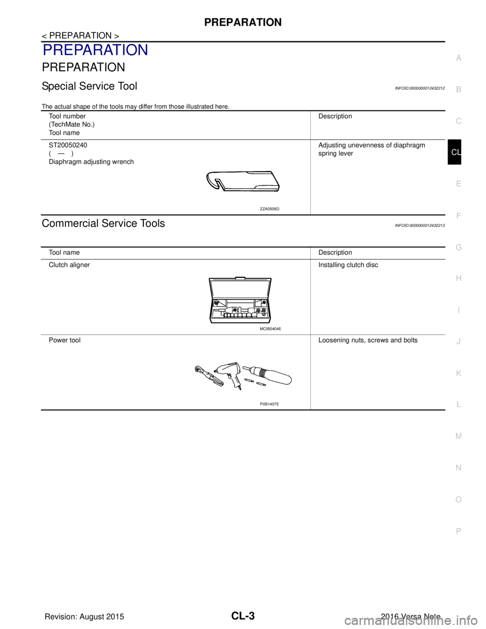
Special Service ToolINFOID:0000000012432212
The actual shape of the tools may di ffer from those illustrated here.
Commercial Service ToolsINFOID:0000000012432213
Tool number
(TechMate No.)
To o l n a m e Description
ST20050240
(—)
Diaphragm adjusting wrench Adjusting unevenness of diaphragm
spring lever
ZZA0508D
To o l n a m e
Description
Clutch aligner Installing clutch disc
Power tool Loosening nuts, screws and bolts
MCIB0404E
PIIB1407E
Revision: August 2015 2016 Versa Note
cardiagn.com
Page 630 of 3641

CL-4
< SYMPTOM DIAGNOSIS >
NOISE, VIBRATION AND HARSHNESS (NVH) TROUBLESHOOTING
SYMPTOM DIAGNOSIS
NOISE, VIBRATION AND HARSHNESS (NVH) TROUBLESHOOTING
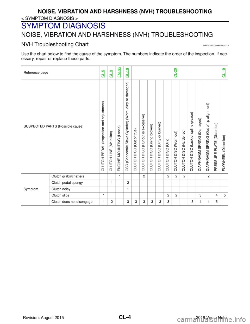
NVH Troubleshooting ChartINFOID:0000000012432214
Use the chart below to find the cause of the symptom. T he numbers indicate the order of the inspection. If nec-
essary, repair or replace these parts.
Reference pageCL-5CL-9EM-86CL-18CL-20CL-19
SUSPECTED PARTS (Possible cause)
CLUTCH PEDAL (Inspection and adjustment)
CLUTCH LINE (Air in line)
ENGINE MOUNTING (Loose)
CSC (Concentric Slave Cylinder) (Worn, dirty or damaged)
CLUTCH DISC (Out of true)
CLUTCH DISC (Ru nout is excessive)
CLUTCH DISC (Lining broken)
CLUTCH DISC (Dirty or burned)
CLUTCH DISC (Oily)
CLUTCH DISC (Worn out)
CLUTCH DISC (Hardened)
CLUTCH DISC (Lack of spline grease)
DIAPHRAGM SPRING (Damaged)
DIAPHRAGM SPRING (Out of tip alignment)
PRESSURE PLATE (Distortion)
FLYWHEEL (Distortion)
Symptom Clutch grabs/chatters
122 2 2 2
Clutch pedal spongy 1 2
Clutch noisy 1
Clutch slips 1 2 23 4 5
Clutch does not disengage 12 333333 3445
Revision: August 2015 2016 Versa Note
cardiagn.com
Page 631 of 3641

CLUTCH PEDALCL-5
< PERIODIC MAINTENANCE >
CEF
G H
I
J
K L
M A
B
CL
N
O P
PERIODIC MAINTENANCE
CLUTCH PEDAL
Inspection and AdjustmentINFOID:0000000012432215
INSPECTION
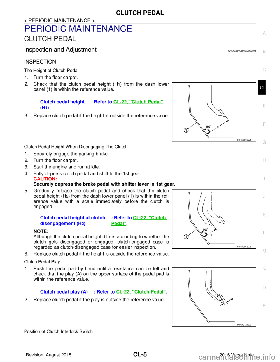
The Height of Clutch Pedal
1. Turn the floor carpet.
2. Check that the clutch pedal height (H
1) from the dash lower
panel (1) is within the reference value.
3. Replace clutch pedal if the height is outside the reference value.
Clutch Pedal Height When Disengaging The Clutch
1. Securely engage the parking brake.
2. Turn the floor carpet.
3. Start the engine and run at idle.
4. Fully depress clutch pedal and shift to the 1st gear. CAUTION:
Securely depress the brake pedal with shifter lever in 1st gear.
5. Gradually release the clutch pedal and check that the clutch pedal height (H
2) from the dash lower panel (1) is within the ref-
erence value with a scale immediately before the clutch is
engaged.
NOTE:
Although the clutch pedal height differs according to whether the
clutch gets disengaged or engaged, clutch-engaged case is
regarded as clutch-disengaged case for easier inspection.
6. Replace clutch pedal if the height is outside the reference value.
Clutch Pedal Play
1. Push the pedal pad by hand until a resistance can be felt and check that the play (A) on the upper surface of the pedal pad is
within the reference value.
2. Replace clutch pedal if the play is outside the reference value.
Position of Clutch Interlock Switch
Clutch pedal height
(H
1) : Refer to
CL-22, "
Clutch Pedal".
JPFIA0065ZZ
Clutch pedal height at clutch
disengagement (H
2) : Refer to CL-22, "
Clutch
Pedal".
JPFIA0068ZZ
Clutch pedal play (A) : Refer to
CL-22, "Clutch Pedal".
JPFIA0121ZZ
Revision: August 2015 2016 Versa Note
cardiagn.com