wheel alignment NISSAN NOTE 2016 Service Owner's Guide
[x] Cancel search | Manufacturer: NISSAN, Model Year: 2016, Model line: NOTE, Model: NISSAN NOTE 2016Pages: 3641, PDF Size: 28.72 MB
Page 3223 of 3641

ST-2
< PRECAUTION >
PRECAUTIONS
PRECAUTION
PRECAUTIONS
Precaution for Supplemental Restraint System (SRS) "AIR BAG" and "SEAT BELT
PRE-TENSIONER"
INFOID:0000000012430493
The Supplemental Restraint System such as “A IR BAG” and “SEAT BELT PRE-TENSIONER”, used along
with a front seat belt, helps to reduce the risk or severity of injury to the driver and front passenger for certain
types of collision. Information necessary to service the system safely is included in the SR and SB section of
this Service Manual.
WARNING:
• To avoid rendering the SRS inopera tive, which could increase the risk of personal injury or death in
the event of a collision which would result in air bag inflation, all maintenance must be performed by
an authorized NISSAN/INFINITI dealer.
• Improper maintenance, including in correct removal and installation of the SRS, can lead to personal
injury caused by unintent ional activation of the system. For re moval of Spiral Cable and Air Bag
Module, see the SR section.
• Do not use electrical test equipmen t on any circuit related to the SRS unless instructed to in this
Service Manual. SRS wiring harn esses can be identified by yellow and/or orange harnesses or har-
ness connectors.
PRECAUTIONS WHEN USING POWER TOOLS (AIR OR ELECTRIC) AND HAMMERS
WARNING:
• When working near the Airbag Diagnosis Sensor Unit or other Airbag System sensors with the Igni-
tion ON or engine running, DO NOT use air or electri c power tools or strike near the sensor(s) with a
hammer. Heavy vibration could activate the sensor( s) and deploy the air bag(s), possibly causing
serious injury.
• When using air or electric power tools or hammers , always switch the Ignition OFF, disconnect the
battery and wait at least three minutes before performing any service.
Service Notice or Precautions for Steering SystemINFOID:0000000012430494
• In case of removing the steering gear, make the final tightening with grounded and unloaded vehicle condi- tion, and then check wheel alignment.
• Observe the following precautions when disassembling.
- Before disassembly, thoroughly clean the outside of the unit.
- Disassembly should be done in a clean work area. It is im portant to prevent the internal parts from becoming
contaminated by dirt or other foreign matter.
- For easier and proper assembly, place disassembled parts in order on a parts rack.
- Use nylon cloth or paper towels to clean the parts; co mmon shop rags can leave lint that might interfere with
their operation.
- Do not reuse non-reusable parts.
- Before assembling, apply the specified grease to the directed parts.
FOR ELECTRIC POWER STEERING (EPS)
• During quick steering, rasping noise may be heard from around the steering wheel. This is not a malfunction.
The noise is an operating noise of the EPS system under normal conditions. If the rasping noise occurs dur-
ing slow steering, this may not be an operating noise of the system. In this case, it is necessary to find out
the location of the noise and repair, if necessary.
• Do not repeat static steering. (Mot or and EPS control unit could be heated.)
Revision: August 2015 2016 Versa Note
cardiagn.com
Page 3226 of 3641

STEERING WHEELST-5
< BASIC INSPECTION >
C
DE
F
H I
J
K L
M A
B
ST
N
O P
BASIC INSPECTION
STEERING WHEEL
InspectionINFOID:0000000012430497
CONDITION OF INSTALLATION
• Check installation conditions of steering gear, front suspension, axle and steering column.
• Check if movement exists when steering wheel is mo ved up and down, to the left and right and to the axial
direction.
• Verify that the steering gear nuts are tightened to specification. Refer to ST-14, "
Exploded View".
STEERING WHEEL PLAY
1. Set the front wheels and tires in the straight-ahead position, start engine, then lightly turn steering wheel
to the left and right until the front wheels start to move. Measure steering wheel movement on the outer
circumference.
2. When the measurement value is outside the standard va lue, check backlash for each joint of steering col-
umn and installation condition of steering gear.
STEERING WHEEL NEUTRAL POSITION
Check steering wheel neutral position using the following procedure:
1. Confirm that front wheel alignment is correct. Refer to FSU-8, "
Adjustment".
2. Set the front wheels and tires in the straight-ahead posit ion, check if steering wheel is in the neutral posi-
tion.
3. If it is not in the neutral position, remo ve steering wheel and reinstall it correctly.
4. If the neutral position cannot be attained by repositi oning the steering wheel two teeth or less on steering
stem, loosen the steering gear outer socket lock nuts, then adjust the inner sockets by the same amount
in the opposite direction.
5. Re-check the front wheel alignment. Refer to FSU-8, "
Adjustment".
STEERING WHEEL TURNING FORCE
1. Park vehicle on a level and dry surface, set parking brake.
2. Tires need to be inflated normal pressure. Refer to WT-54, "
Tire Air Pressure".
3. Start engine.
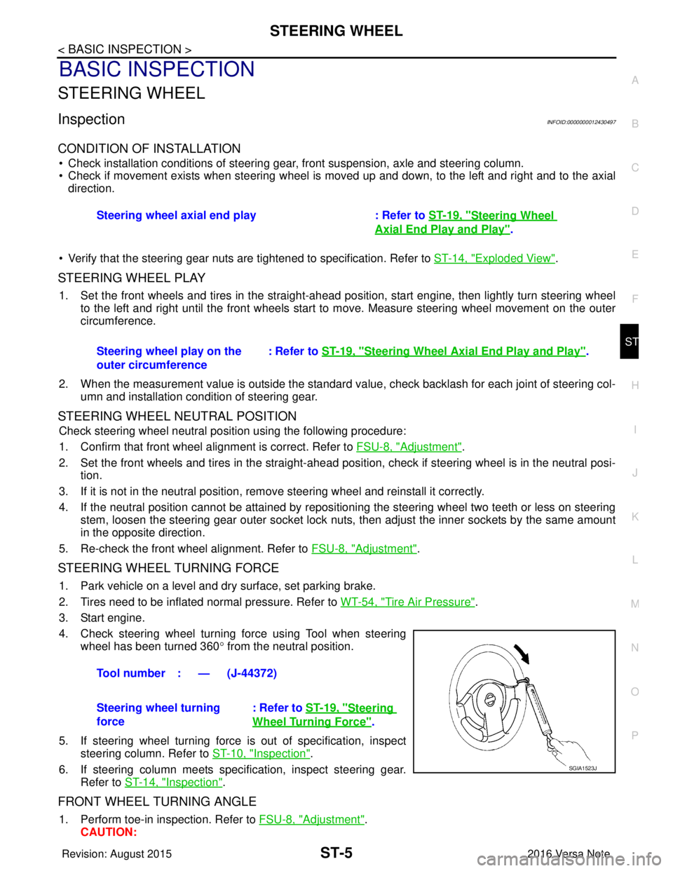
4. Check steering wheel turning force using Tool when steering wheel has been turned 360 ° from the neutral position.
5. If steering wheel turning force is out of specification, inspect steering column. Refer to ST-10, "
Inspection".
6. If steering column meets specification, inspect steering gear. Refer to ST-14, "
Inspection".
FRONT WHEEL TURNING ANGLE
1. Perform toe-in inspection. Refer to FSU-8, "Adjustment".
CAUTION: Steering wheel axial end play : Refer to
ST-19, "
Steering Wheel
Axial End Play and Play".
Steering wheel play on the
outer circumference : Refer to
ST-19, "
Steering Wheel Axia l End Play and Play".
Tool number : — (J-44372)
Steering wheel turning
force : Refer to
ST-19, "
Steering
Wheel Turning Force".
SGIA1523J
Revision: August 2015 2016 Versa Note
cardiagn.com
Page 3236 of 3641

STEERING GEAR AND LINKAGEST-15
< REMOVAL AND INSTALLATION >
C
DE
F
H I
J
K L
M A
B
ST
N
O P
INSPECTION AFTER INSTALLATION
• Rotate steering wheel to make sure it is centered and there is no binding, noise or excessive steering effort.
• Make sure that the number of turns are the same from the straight-ahead position to the left and right locks.
• Check each part of steering system for damage or ot her malfunctions. Replace if there are any abnormal
conditions.
• Check the steering wheel play, neutral position steering wheel, steering wheel turning force, and front wheel
turning angle. Refer to ST-5, "
Inspection".
• Check wheel alignment. Refer to FSU-8, "
Adjustment".
• Check the neutral position of the steering angle sensor. Refer to BRC-55, "
ADJUSTMENT OF STEERING
ANGLE SENSOR NEUTRAL POSITION : Description".
Revision: August 2015 2016 Versa Note
cardiagn.com
Page 3238 of 3641

STEERING GEAR AND LINKAGEST-17
< UNIT DISASSEMBLY AND ASSEMBLY >
C
DE
F
H I
J
K L
M A
B
ST
N
O P
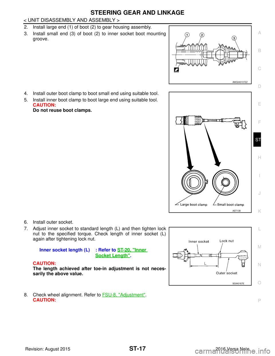
2. Install large end (1) of boot (2) to gear housing assembly.
3. Install small end (3) of boot (2) to inner socket boot mounting groove.
4. Install outer boot clamp to boot small end using suitable tool.
5. Install inner boot clamp to boot large end using suitable tool. CAUTION:
Do not reuse boot clamps.
6. Install outer socket.
7. Adjust inner socket to standard length (L) and then tighten lock nut to the specified torque. Check length of inner socket (L)
again after tightening lock nut.
CAUTION:
The length achieved after toe-in adjustment is not neces-
sarily the above value.
8. Check wheel alignment. Refer to FSU-8, "
Adjustment".
CAUTION:
AWGIA0107ZZ
AST139
Inner socket length (L) : Refer to ST-20, "Inner
Socket Length".
SGIA0167E
Revision: August 2015 2016 Versa Note
cardiagn.com