push-button ignition switch NISSAN NOTE 2016 Service Manual Online
[x] Cancel search | Manufacturer: NISSAN, Model Year: 2016, Model line: NOTE, Model: NISSAN NOTE 2016Pages: 3641, PDF Size: 28.72 MB
Page 2969 of 3641

SEC-112
< SYMPTOM DIAGNOSIS >[WITH INTELLIGENT KEY SYSTEM]
ENGINE DOES NOT START WHEN INTELLI
GENT KEY IS INSIDE OF VEHICLE
SYMPTOM DIAGNOSIS
ENGINE DOES NOT START WHEN INTELLIGENT KEY IS INSIDE OF VE-
HICLE
DescriptionINFOID:0000000012430432
Engine does not start when push-button ignition swit ch is pressed while carrying Intelligent Key.
NOTE:
• Check that vehicle is under the condition shown in “Conditions of vehicle” before starting diagnosis, and check each symptom.
• The engine start function, door lock function, power di stribution system, and NATS-IVIS/NVIS in the Intelli-
gent Key system are closely related to each other regarding control. The vehicle security function can oper-
ate only when the door lock and power dist ribution system are operating normally.
Conditions of Vehicle (Operating Conditions)
• “ENGINE START BY I-KEY” setting in “Work suppor t” in “INTELLIGENT KEY” of “BCM” is ON.
• One or more of Intelligent Keys with registered Intelligent Key ID is in the vehicle.
Diagnosis ProcedureINFOID:0000000012430433
1.PERFORM WORK SUPPORT
Perform “INSIDE ANT DIAGNOSIS” in “Work Support” of “INTELLIGENT KEY” of “BCM” using CONSULT.
Refer to BCS-22, "
INTELLIGENT KEY : CONSULT Func tion (BCM - INTELLIGENT KEY)".
>> GO TO 2.
2.PERFORM SELF-DIAGNOSIS RESULT
Select “Self Diagnostic Result” mode of “BCM”, and check whether or not DTC of inside key antenna is
detected.
Is DTC detected?
YES >> Perform the trouble diagnosis for detected DTC. Refer to BCS-50, "DTCIndex".
NO >> GO TO 3.
3.CHECK PUSH-BUTTON IGNITION SWITCH
Check push-button ignition switch.
Refer to SEC-66, "
Component Inspection".
Is the operation normal?
YES >> GO TO 4.
NO >> Repair or replace malfunctioning parts.
4.CONFIRM THE OPERATION
Confirm the operation again.
Is the inspection normal?
YES >> Check intermittent incident. Refer to GI-42, "Intermittent Incident".
NO >> GO TO 1.
Revision: August 2015 2016 Versa Note
cardiagn.com
Page 2972 of 3641

PUSH-BUTTON IGNITION SWITCHSEC-115
< REMOVAL AND INSTALLATION > [WITH INTELLIGENT KEY SYSTEM]
C
D
E
F
G H
I
J
L
M A
B
SEC
N
O P
PUSH-BUTTON IGNITION SWITCH
Removal and InstallationINFOID:0000000012430437
REMOVAL
1. Remove NATS antenna amp. Refer to SEC-114, "Removal and Installation".
2. Release pawls and remove the push-button ignition switch (1). : Pawl
INSTALLATION
Installation is in the reverse order of removal.
ALKIA3180ZZ
Revision: August 2015 2016 Versa Note
cardiagn.com
Page 2986 of 3641

DIAGNOSIS SYSTEM (IPDM E/R)SEC-129
< SYSTEM DESCRIPTION > [WITHOUT INTELLIGENT KEY SYSTEM]
C
D
E
F
G H
I
J
L
M A
B
SEC
N
O P
ECU IDENTIFICATION
The IPDM E/R part number is displayed.
SELF DIAGNOSTIC RESULT
Refer to PCS-20, "DTCIndex".
DATA MONITOR
ACTIVE TEST
Data Monitor The IPDM E/R input/output data is displayed in real time.
Active Test The IPDM E/R activates outputs to test components.
CAN Diag Support Mntr The result of transmit/receive diagnosis of CAN communication is displayed.
Direct Diagnostic Mode
Description
Monitor Item [Unit]Main
Signals Description
MOTOR FAN REQ [1/2/3/4] ×Indicates cooling fan speed signal received from ECM on CAN communication
line
AC COMP REQ [On/Off] ×Indicates A/C compressor request signal received from ECM on CAN commu-
nication line
TAIL&CLR REQ [On/Off] ×Indicates position light request signal
received from BCM on CAN communica-
tion line
HL LO REQ [On/Off] ×Indicates low beam request signal received from BCM on CAN communication
line
HL HI REQ [On/Off] ×Indicates high beam request signal received from BCM on CAN communication
line
FR FOG REQ [On/Off] ×Indicates front fog light request signal received from BCM on CAN communica-
tion line
FR WIP REQ [Stop/1LOW/Low/Hi] ×Indicates front wiper request signal received from BCM on CAN communication
line
WIP AUTO STOP [STOP P/ACT P] ×Indicates condition of front wiper auto stop signal
WIP PROT [Off/BLOCK] ×Indicates condition of front wiper fail-safe operation
IGN RLY1 -REQ [On/Off] Indicates ignition switch ON signal received from BCM on CAN communication
line
IGN RLY [On/Off] ×Indicates condition of ignition relay
PUSH SW [On/Off] Indicates condition of push-button ignition switch
INTER/NP SW [On/Off] Indicates condition of CVT shift position
ST RLY CONT [On/Off] Indicates starter relay status signal received from BCM on CAN communication
line
IHBT RLY -REQ [On/Off] Indicates starter control relay signal received from BCM on CAN communication
line
ST/INHI RLY [Off/ ST /INHI] Indicates condition of starter relay and starter control relay
DETENT SW [On/Off] Indicates condition of CVT shift selector (park position switch)
DTRL REQ [Off] Indicates daytime running light request signal received from BCM on CAN com-
munication line
THFT HRN REQ [On/Off] Indicates theft warning horn request signal received from BCM on CAN commu-
nication line
HORN CHIRP [On/Off] Indicates horn reminder signal received from BCM on CAN communication line
Test item Description
HORN This test is able to check horn operation [On].
FRONT WIPER This test is able to check wiper motor operation [Hi/Lo/Off].
Revision: August 2015 2016 Versa Note
cardiagn.com
Page 3537 of 3641

WCS-22
< SYSTEM DESCRIPTION >
DIAGNOSIS SYSTEM (BCM) (WITH INTELLIGENT KEY SYSTEM)
BUZZER
BUZZER : CONSULT Function (BCM - BUZZER)INFOID:0000000012542987
DATA MONITOR
ACTIVE TEST
Monitor Item [Unit] Description
PUSH SW [On/Off] Indicates condition of push-button ignition switch.
UNLK SEN -DR [On/Off] Indicates condition of door unlock sensor.
VEH SPEED 1 [km/h] Indicates vehicle speed signal received from ABS on CAN communication line.
TAIL LAMP SW [On/Off] Indicates condition of combination switch.
FR FOG SW [On/Off] Indicates condition of front fog lamp switch.
DOOR SW-DR [On/Off] Indicates condition of front door switch LH.
CDL LOCK SW [On/Off] Indicates condition of lock signal from door lock and unlock switch.
Test Item Description
ID REGIST WARNING This test is able to check TPMS transmitter ID regist warning chime operation [On/Off].
SEAT BELT WARN TEST This test is able to check seat belt warning chime operation [On/Off].
LIGHT WARN ALM This test is able to check light warning chime operation [On/Off].
Revision: August 2015 2016 Versa Note
cardiagn.com
Page 3579 of 3641

WW-14
< SYSTEM DESCRIPTION >
DIAGNOSIS SYSTEM (BCM) (WITH INTELLIGENT KEY SYSTEM)
WIPER
WIPER : CONSULT Function (BCM - WIPER)INFOID:0000000012542536
DATA MONITOR
ACTIVE TEST
WORK SUPPORT
* : Initial settingMonitor Item [Unit]
Description
PUSH SW [On/Off] Indicates condition of push-button ignition switch.
VEH SPEED 1 [km/h] Indicates vehicle speed signal receiv ed from ABS on CAN communication line.
FR WIPER HI [On/Off]
Indicates condition of wiper operation of combination switch.
FR WIPER LOW [On/Off]
FR WASHER SW [On/Off]
FR WIPER INT [On/Off]
FR WIPER STOP [On/Off]
Indicates front wiper auto stop signal received from IPDM E/R on CAN communication
line.
INT VOLUME [1 − 7] Indicates condition of intermittent wiper operation of combination switch.
RR WIPER ON [On/Off] Indicates condition of rear wiper operation of combination switch.
RR WIPER INT [On/Off]
RR WASHER SW [On/Off]
RR WIPER STOP [On/Off] Indicates rear wiper motor auto stop input from rear wiper motor.
Test Item Description
FR WIPER This test is able to check front wiper operation [INT/Lo/Hi/Off].
RR WIPER This test is able to check rear wiper operation [On/Off].
Support ItemSetting Description
WIPER SPEED SETTING On Front wiper intermittent time linked with vehicle speed and wiper dial position.
Off* Front wiper intermittent time linked with wiper dial position.
Revision: August 2015
2016 Versa Note
cardiagn.com
Page 3584 of 3641
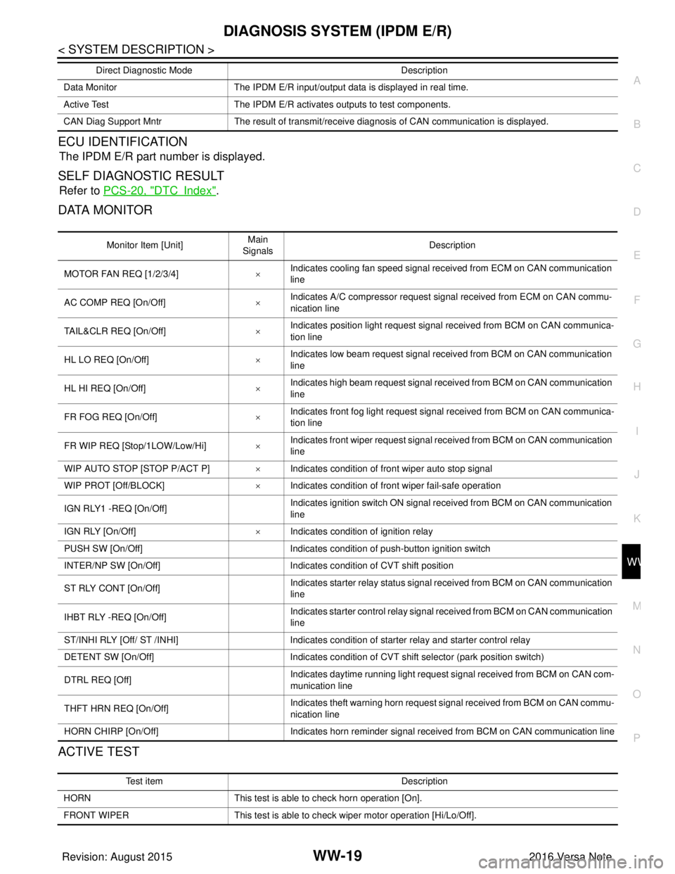
DIAGNOSIS SYSTEM (IPDM E/R)WW-19
< SYSTEM DESCRIPTION >
C
DE
F
G H
I
J
K
M A
B
WW
N
O P
ECU IDENTIFICATION
The IPDM E/R part number is displayed.
SELF DIAGNOSTIC RESULT
Refer to PCS-20, "DTCIndex".
DATA MONITOR
ACTIVE TEST
Data Monitor The IPDM E/R input/output data is displayed in real time.
Active Test The IPDM E/R activates outputs to test components.
CAN Diag Support Mntr The result of transmit/receive diagnosis of CAN communication is displayed.
Direct Diagnostic Mode
Description
Monitor Item [Unit]Main
Signals Description
MOTOR FAN REQ [1/2/3/4] ×Indicates cooling fan speed signal received from ECM on CAN communication
line
AC COMP REQ [On/Off] ×Indicates A/C compressor request signal received from ECM on CAN commu-
nication line
TAIL&CLR REQ [On/Off] ×Indicates position light request signal
received from BCM on CAN communica-
tion line
HL LO REQ [On/Off] ×Indicates low beam request signal received from BCM on CAN communication
line
HL HI REQ [On/Off] ×Indicates high beam request signal received from BCM on CAN communication
line
FR FOG REQ [On/Off] ×Indicates front fog light request signal received from BCM on CAN communica-
tion line
FR WIP REQ [Stop/1LOW/Low/Hi] ×Indicates front wiper request signal received from BCM on CAN communication
line
WIP AUTO STOP [STOP P/ACT P] ×Indicates condition of front wiper auto stop signal
WIP PROT [Off/BLOCK] ×Indicates condition of front wiper fail-safe operation
IGN RLY1 -REQ [On/Off] Indicates ignition switch ON signal received from BCM on CAN communication
line
IGN RLY [On/Off] ×Indicates condition of ignition relay
PUSH SW [On/Off] Indicates condition of push-button ignition switch
INTER/NP SW [On/Off] Indicates condition of CVT shift position
ST RLY CONT [On/Off] Indicates starter relay status signal received from BCM on CAN communication
line
IHBT RLY -REQ [On/Off] Indicates starter control relay signal received from BCM on CAN communication
line
ST/INHI RLY [Off/ ST /INHI] Indicates condition of starter relay and starter control relay
DETENT SW [On/Off] Indicates condition of CVT shift selector (park position switch)
DTRL REQ [Off] Indicates daytime running light request signal received from BCM on CAN com-
munication line
THFT HRN REQ [On/Off] Indicates theft warning horn request signal received from BCM on CAN commu-
nication line
HORN CHIRP [On/Off] Indicates horn reminder signal received from BCM on CAN communication line
Test item Description
HORN This test is able to check horn operation [On].
FRONT WIPER This test is able to check wiper motor operation [Hi/Lo/Off].
Revision: August 2015 2016 Versa Note
cardiagn.com