relay NISSAN PATROL 1998 Y61 / 5.G Electrical System User Guide
[x] Cancel search | Manufacturer: NISSAN, Model Year: 1998, Model line: PATROL, Model: NISSAN PATROL 1998 Y61 / 5.GPages: 326, PDF Size: 11.36 MB
Page 207 of 326
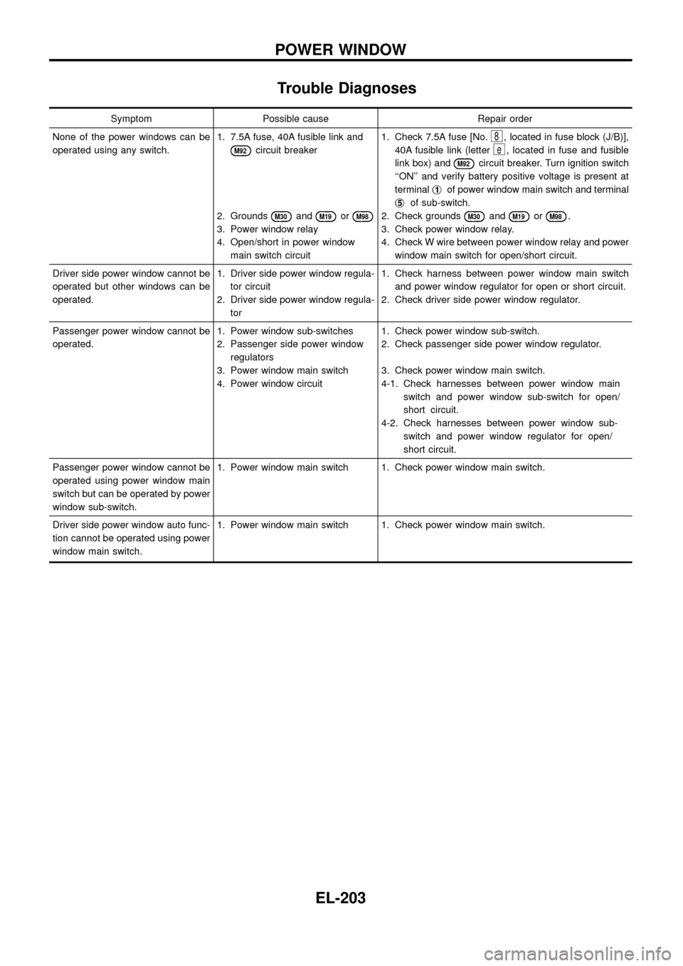
Trouble Diagnoses
Symptom Possible cause Repair order
None of the power windows can be
operated using any switch.1. 7.5A fuse, 40A fusible link and
M92circuit breaker
2. Grounds
M30andM19orM98
3. Power window relay
4. Open/short in power window
main switch circuit1. Check 7.5A fuse [No.
8, located in fuse block (J/B)],
40A fusible link (letter
e, located in fuse and fusible
link box) and
M92circuit breaker. Turn ignition switch
``ON'' and verify battery positive voltage is present at
terminalj
1of power window main switch and terminal
j
5of sub-switch.
2. Check grounds
M30andM19orM98.
3. Check power window relay.
4. Check W wire between power window relay and power
window main switch for open/short circuit.
Driver side power window cannot be
operated but other windows can be
operated.1. Driver side power window regula-
tor circuit
2. Driver side power window regula-
tor1. Check harness between power window main switch
and power window regulator for open or short circuit.
2. Check driver side power window regulator.
Passenger power window cannot be
operated.1. Power window sub-switches
2. Passenger side power window
regulators
3. Power window main switch
4. Power window circuit1. Check power window sub-switch.
2. Check passenger side power window regulator.
3. Check power window main switch.
4-1. Check harnesses between power window main
switch and power window sub-switch for open/
short circuit.
4-2. Check harnesses between power window sub-
switch and power window regulator for open/
short circuit.
Passenger power window cannot be
operated using power window main
switch but can be operated by power
window sub-switch.1. Power window main switch 1. Check power window main switch.
Driver side power window auto func-
tion cannot be operated using power
window main switch.1. Power window main switch 1. Check power window main switch.
POWER WINDOW
EL-203
Page 238 of 326
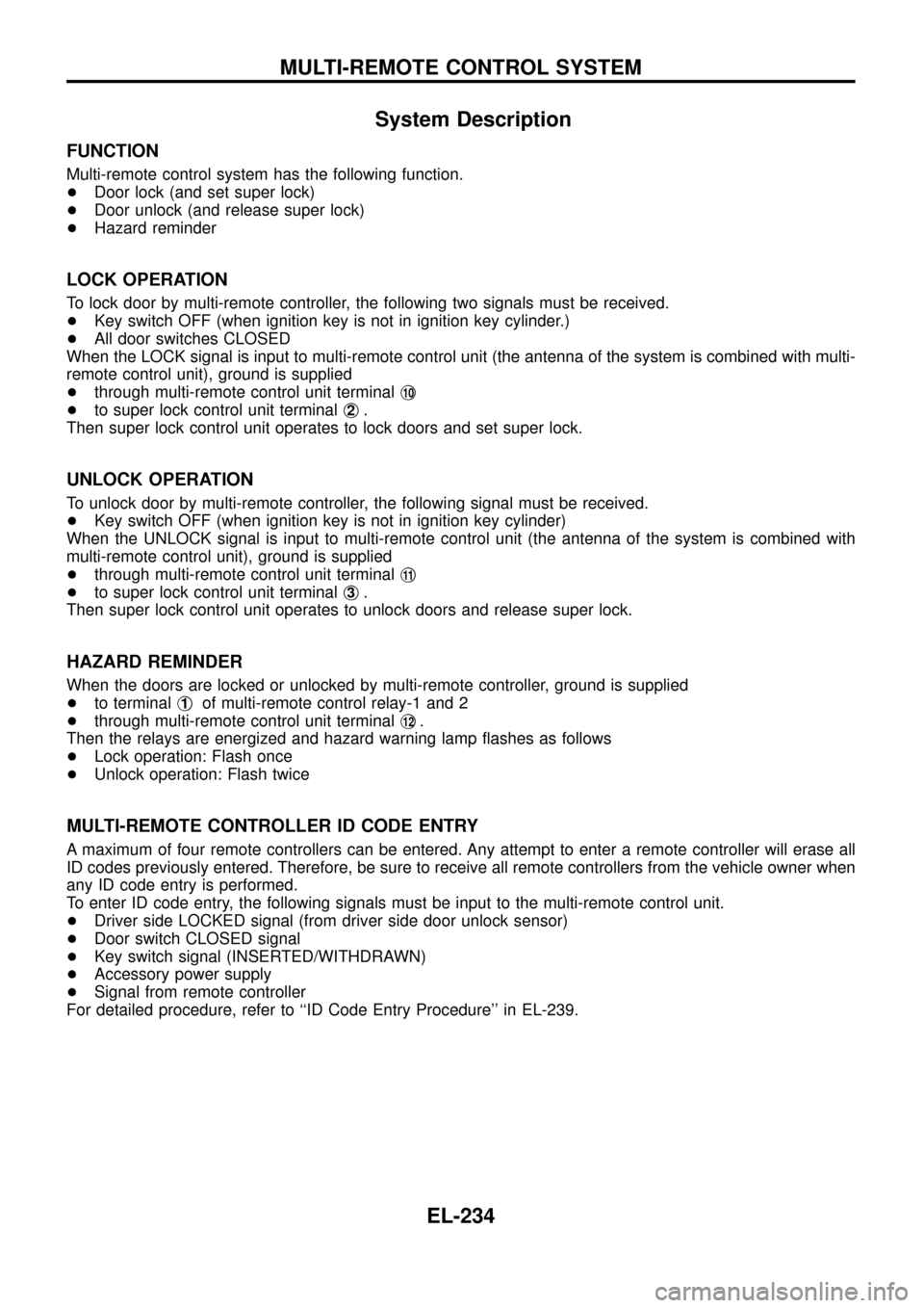
System Description
FUNCTION
Multi-remote control system has the following function.
+Door lock (and set super lock)
+Door unlock (and release super lock)
+Hazard reminder
LOCK OPERATION
To lock door by multi-remote controller, the following two signals must be received.
+Key switch OFF (when ignition key is not in ignition key cylinder.)
+All door switches CLOSED
When the LOCK signal is input to multi-remote control unit (the antenna of the system is combined with multi-
remote control unit), ground is supplied
+through multi-remote control unit terminalj
10
+to super lock control unit terminalj2.
Then super lock control unit operates to lock doors and set super lock.
UNLOCK OPERATION
To unlock door by multi-remote controller, the following signal must be received.
+Key switch OFF (when ignition key is not in ignition key cylinder)
When the UNLOCK signal is input to multi-remote control unit (the antenna of the system is combined with
multi-remote control unit), ground is supplied
+through multi-remote control unit terminalj
11
+to super lock control unit terminalj3.
Then super lock control unit operates to unlock doors and release super lock.
HAZARD REMINDER
When the doors are locked or unlocked by multi-remote controller, ground is supplied
+to terminalj
1of multi-remote control relay-1 and 2
+through multi-remote control unit terminalj
12.
Then the relays are energized and hazard warning lamp ¯ashes as follows
+Lock operation: Flash once
+Unlock operation: Flash twice
MULTI-REMOTE CONTROLLER ID CODE ENTRY
A maximum of four remote controllers can be entered. Any attempt to enter a remote controller will erase all
ID codes previously entered. Therefore, be sure to receive all remote controllers from the vehicle owner when
any ID code entry is performed.
To enter ID code entry, the following signals must be input to the multi-remote control unit.
+Driver side LOCKED signal (from driver side door unlock sensor)
+Door switch CLOSED signal
+Key switch signal (INSERTED/WITHDRAWN)
+Accessory power supply
+Signal from remote controller
For detailed procedure, refer to ``ID Code Entry Procedure'' in EL-239.
MULTI-REMOTE CONTROL SYSTEM
EL-234
Page 241 of 326
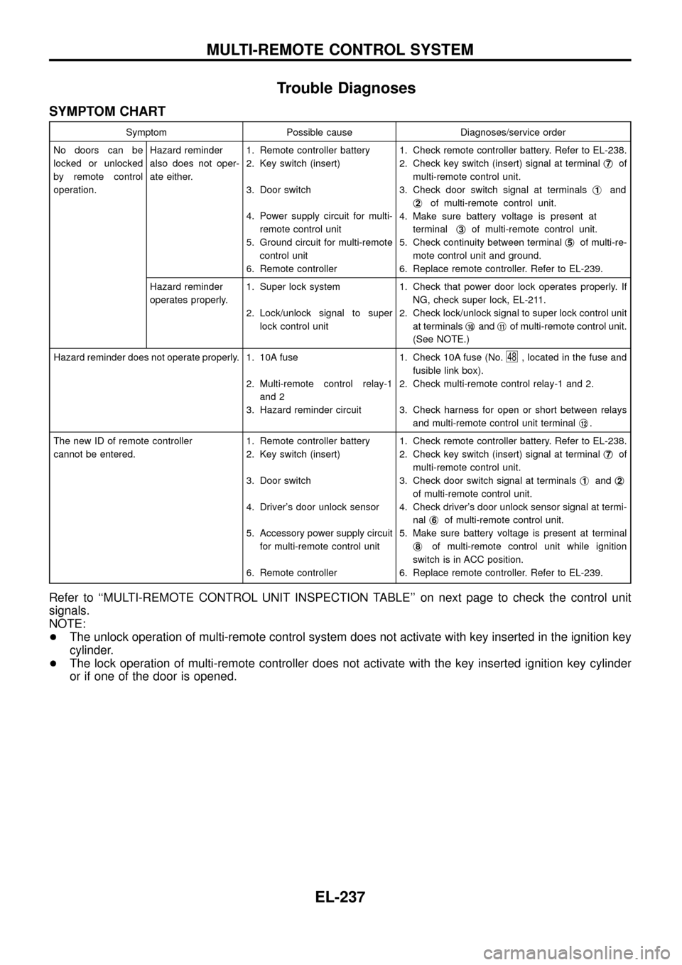
Trouble Diagnoses
SYMPTOM CHART
Symptom Possible cause Diagnoses/service order
No doors can be
locked or unlocked
by remote control
operation.Hazard reminder
also does not oper-
ate either.1. Remote controller battery
2. Key switch (insert)
3. Door switch
4. Power supply circuit for multi-
remote control unit
5. Ground circuit for multi-remote
control unit
6. Remote controller1. Check remote controller battery. Refer to EL-238.
2. Check key switch (insert) signal at terminalj
7of
multi-remote control unit.
3. Check door switch signal at terminalsj
1and
j
2of multi-remote control unit.
4. Make sure battery voltage is present at
terminalj
3of multi-remote control unit.
5. Check continuity between terminalj
5of multi-re-
mote control unit and ground.
6. Replace remote controller. Refer to EL-239.
Hazard reminder
operates properly.1. Super lock system
2. Lock/unlock signal to super
lock control unit1. Check that power door lock operates properly. If
NG, check super lock, EL-211.
2. Check lock/unlock signal to super lock control unit
at terminalsj
10andj11of multi-remote control unit.
(See NOTE.)
Hazard reminder does not operate properly. 1. 10A fuse
2. Multi-remote control relay-1
and 2
3. Hazard reminder circuit1. Check 10A fuse (No.
48, located in the fuse and
fusible link box).
2. Check multi-remote control relay-1 and 2.
3. Check harness for open or short between relays
and multi-remote control unit terminalj
12.
The new ID of remote controller
cannot be entered.1. Remote controller battery
2. Key switch (insert)
3. Door switch
4. Driver's door unlock sensor
5. Accessory power supply circuit
for multi-remote control unit
6. Remote controller1. Check remote controller battery. Refer to EL-238.
2. Check key switch (insert) signal at terminalj
7of
multi-remote control unit.
3. Check door switch signal at terminalsj
1andj2
of multi-remote control unit.
4. Check driver's door unlock sensor signal at termi-
nalj
6of multi-remote control unit.
5. Make sure battery voltage is present at terminal
j
8of multi-remote control unit while ignition
switch is in ACC position.
6. Replace remote controller. Refer to EL-239.
Refer to ``MULTI-REMOTE CONTROL UNIT INSPECTION TABLE'' on next page to check the control unit
signals.
NOTE:
+The unlock operation of multi-remote control system does not activate with key inserted in the ignition key
cylinder.
+The lock operation of multi-remote controller does not activate with the key inserted ignition key cylinder
or if one of the door is opened.
MULTI-REMOTE CONTROL SYSTEM
EL-237
Page 242 of 326
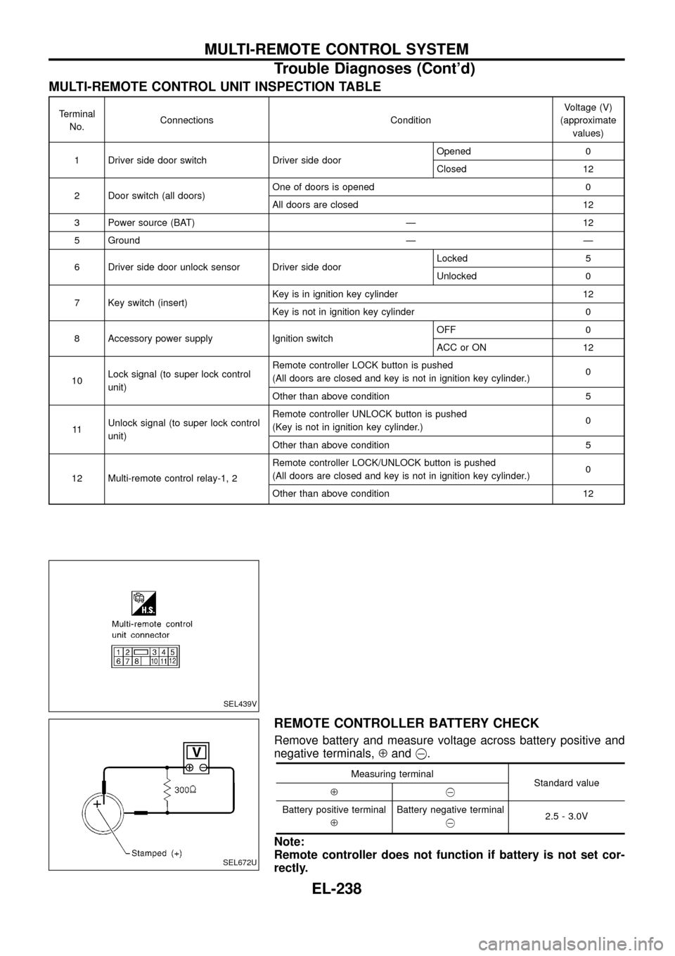
MULTI-REMOTE CONTROL UNIT INSPECTION TABLE
Terminal
No.Connections ConditionVoltage (V)
(approximate
values)
1 Driver side door switch Driver side doorOpened 0
Closed 12
2 Door switch (all doors)One of doors is opened 0
All doors are closed 12
3 Power source (BAT) Ð 12
5 Ground Ð Ð
6 Driver side door unlock sensor Driver side doorLocked 5
Unlocked 0
7 Key switch (insert)Key is in ignition key cylinder 12
Key is not in ignition key cylinder 0
8 Accessory power supply Ignition switchOFF 0
ACC or ON 12
10Lock signal (to super lock control
unit)Remote controller LOCK button is pushed
(All doors are closed and key is not in ignition key cylinder.)0
Other than above condition 5
11Unlock signal (to super lock control
unit)Remote controller UNLOCK button is pushed
(Key is not in ignition key cylinder.)0
Other than above condition 5
12 Multi-remote control relay-1, 2Remote controller LOCK/UNLOCK button is pushed
(All doors are closed and key is not in ignition key cylinder.)0
Other than above condition 12
REMOTE CONTROLLER BATTERY CHECK
Remove battery and measure voltage across battery positive and
negative terminals,Åand@.
Measuring terminal
Standard value
Å@
Battery positive terminal
ÅBattery negative terminal
@2.5 - 3.0V
Note:
Remote controller does not function if battery is not set cor-
rectly.
SEL439V
SEL672U
MULTI-REMOTE CONTROL SYSTEM
Trouble Diagnoses (Cont'd)
EL-238
Page 279 of 326
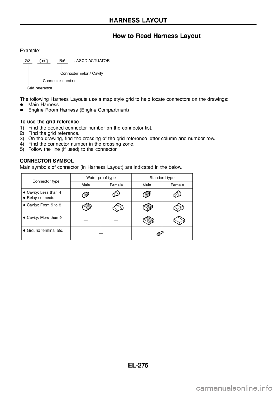
How to Read Harness Layout
Example:
G2E1B/6: ASCD ACTUATOR
Connector color / Cavity
Connector number
Grid reference
The following Harness Layouts use a map style grid to help locate connectors on the drawings:
+Main Harness
+Engine Room Harness (Engine Compartment)
To use the grid reference
1) Find the desired connector number on the connector list.
2) Find the grid reference.
3) On the drawing, ®nd the crossing of the grid reference letter column and number row.
4) Find the connector number in the crossing zone.
5) Follow the line (if used) to the connector.
CONNECTOR SYMBOL
Main symbols of connector (in Harness Layout) are indicated in the below.
Connector typeWater proof type Standard type
Male Female Male Female
+Cavity: Less than 4
+Relay connector
+Cavity: From 5 to 8
+Cavity: More than 9
ÐÐ
+Ground terminal etc.
Ð
HARNESS LAYOUT
EL-275