NISSAN PATROL 1998 Y61 / 5.G Propeller Shaft And Differential Carrier Workshop Manual
Manufacturer: NISSAN, Model Year: 1998, Model line: PATROL, Model: NISSAN PATROL 1998 Y61 / 5.GPages: 54, PDF Size: 1.85 MB
Page 1 of 54
PROPELLER SHAFT &
DIFFERENTIAL CARRIER
SECTION
PD
CONTENTS
PREPARATION................................................................1
Special Service Tools ..................................................1
NOISE, VIBRATION AND HARSHNESS (NVH)
TROUBLESHOOTING.....................................................4
NVH Troubleshooting Chart.........................................4
PROPELLER SHAFT......................................................5
Front Propeller Shaft ...................................................5
Rear Propeller Shaft ....................................................5
On-vehicle Service.......................................................6
Removal and Installation .............................................7
Inspection.....................................................................7
Disassembly.................................................................7
Assembly .....................................................................8
ON-VEHICLE SERVICE (Final Drive)..........................10
Front Oil Seal Replacement ......................................10
REMOVAL AND INSTALLATION.................................. 11
Removal ..................................................................... 11
Installation .................................................................. 11
FRONT FINAL DRIVE...................................................12
REAR FINAL DRIVE.....................................................13
DISASSEMBLY..............................................................14
Pre-inspection ............................................................14
Differential Carrier......................................................15
Differential Case ........................................................17
INSPECTION..................................................................19
Ring Gear and Drive Pinion ......................................19
Differential Case Assembly........................................19Bearing.......................................................................19
LIMITED SLIP DIFFERENTIAL.....................................20
Preparation for Disassembly .....................................20
Disassembly...............................................................21
Inspection...................................................................21
Adjustment .................................................................23
Assembly ...................................................................24
ADJUSTMENT...............................................................27
Drive Pinion Height ....................................................27
Tooth Contact.............................................................29
ASSEMBLY....................................................................31
Differential Case Ð 4-pinion type Ð.........................31
Differential Case Ð 2-pinion type Ð.........................32
Differential Carrier......................................................33
DIFFERENTIAL LOCK..................................................37
Actuator and Fork ......................................................37
Disassembly...............................................................38
Inspection...................................................................39
Assembly ...................................................................40
System Description ....................................................43
Component Parts Location ........................................44
Wiring Diagram Ð DIFF/L Ð/LHD Models ...............45
Wiring Diagram Ð DIFF/L Ð/RHD Models ...............47
Electrical Components Inspection .............................49
SERVICE DATA AND SPECIFICATIONS (SDS)..........51
Propeller Shaft ...........................................................51
Final Drive..................................................................52
PD
Page 2 of 54
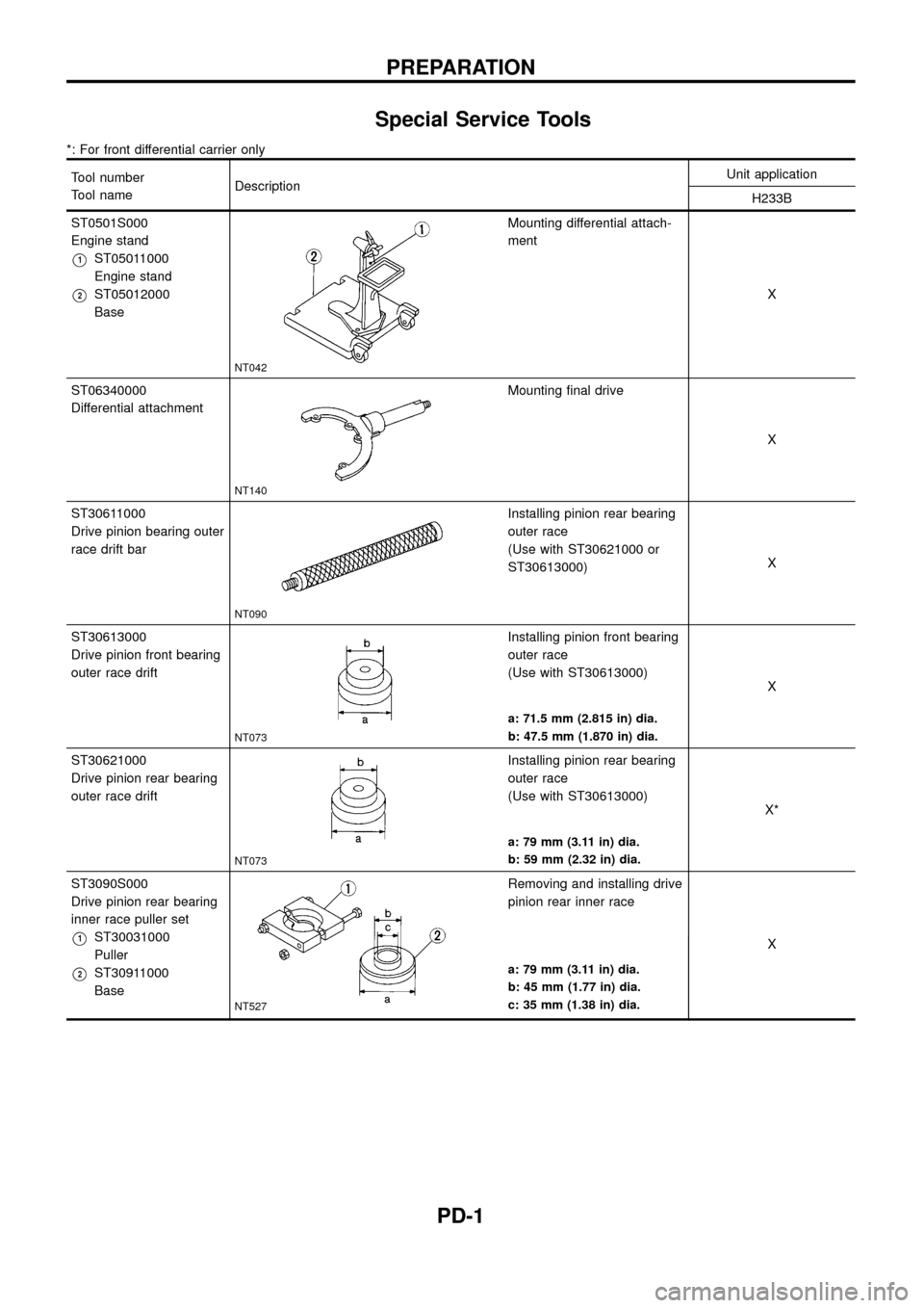
Special Service Tools
*: For front differential carrier only
Tool number
Tool nameDescriptionUnit application
H233B
ST0501S000
Engine stand
V1ST05011000
Engine stand
V2ST05012000
Base
NT042
Mounting differential attach-
ment
X
ST06340000
Differential attachment
NT140
Mounting ®nal drive
X
ST30611000
Drive pinion bearing outer
race drift bar
NT090
Installing pinion rear bearing
outer race
(Use with ST30621000 or
ST30613000)X
ST30613000
Drive pinion front bearing
outer race drift
NT073
Installing pinion front bearing
outer race
(Use with ST30613000)
X
a: 71.5 mm (2.815 in) dia.
b: 47.5 mm (1.870 in) dia.
ST30621000
Drive pinion rear bearing
outer race drift
NT073
Installing pinion rear bearing
outer race
(Use with ST30613000)
X*
a: 79 mm (3.11 in) dia.
b: 59 mm (2.32 in) dia.
ST3090S000
Drive pinion rear bearing
inner race puller set
V1ST30031000
Puller
V2ST30911000
Base
NT527
Removing and installing drive
pinion rear inner race
X
a: 79 mm (3.11 in) dia.
b: 45 mm (1.77 in) dia.
c: 35 mm (1.38 in) dia.
PREPARATION
PD-1
Page 3 of 54
Tool number
Tool nameDescriptionUnit application
H233B
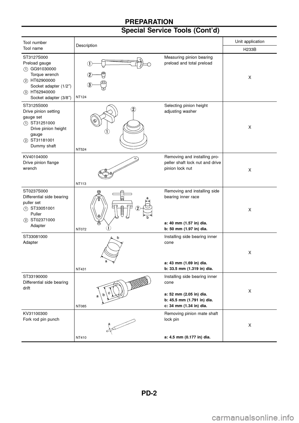
ST3127S000
Preload gauge
V1GG91030000
Torque wrench
V2HT62900000
Socket adapter (1/2²)
V3HT62940000
Socket adapter (3/8²)NT124
Measuring pinion bearing
preload and total preload
X
ST3125S000
Drive pinion setting
gauge set
V1ST31251000
Drive pinion height
gauge
V2ST31181001
Dummy shaft
NT524
Selecting pinion height
adjusting washer
X
KV40104000
Drive pinion ¯ange
wrench
NT113
Removing and installing pro-
peller shaft lock nut and drive
pinion lock nut
X
ST0237S000
Differential side bearing
puller set
V1ST33051001
Puller
V2ST02371000
Adapter
NT072
Removing and installing side
bearing inner race
X
a: 40 mm (1.57 in) dia.
b: 50 mm (1.97 in) dia.
ST33081000
Adapter
NT431
Installing side bearing inner
cone
X
a: 43 mm (1.69 in) dia.
b: 33.5 mm (1.319 in) dia.
ST33190000
Differential side bearing
drift
NT085
Installing side bearing inner
cone
X
a: 52 mm (2.05 in) dia.
b: 45.5 mm (1.791 in) dia.
c: 34 mm (1.34 in) dia.
KV31100300
Fork rod pin punch
NT410
Removing pinion mate shaft
lock pin
X
a: 4.5 mm (0.177 in) dia.
PREPARATION
Special Service Tools (Cont'd)
PD-2
Page 4 of 54
Tool number
Tool nameDescriptionUnit application
H233B
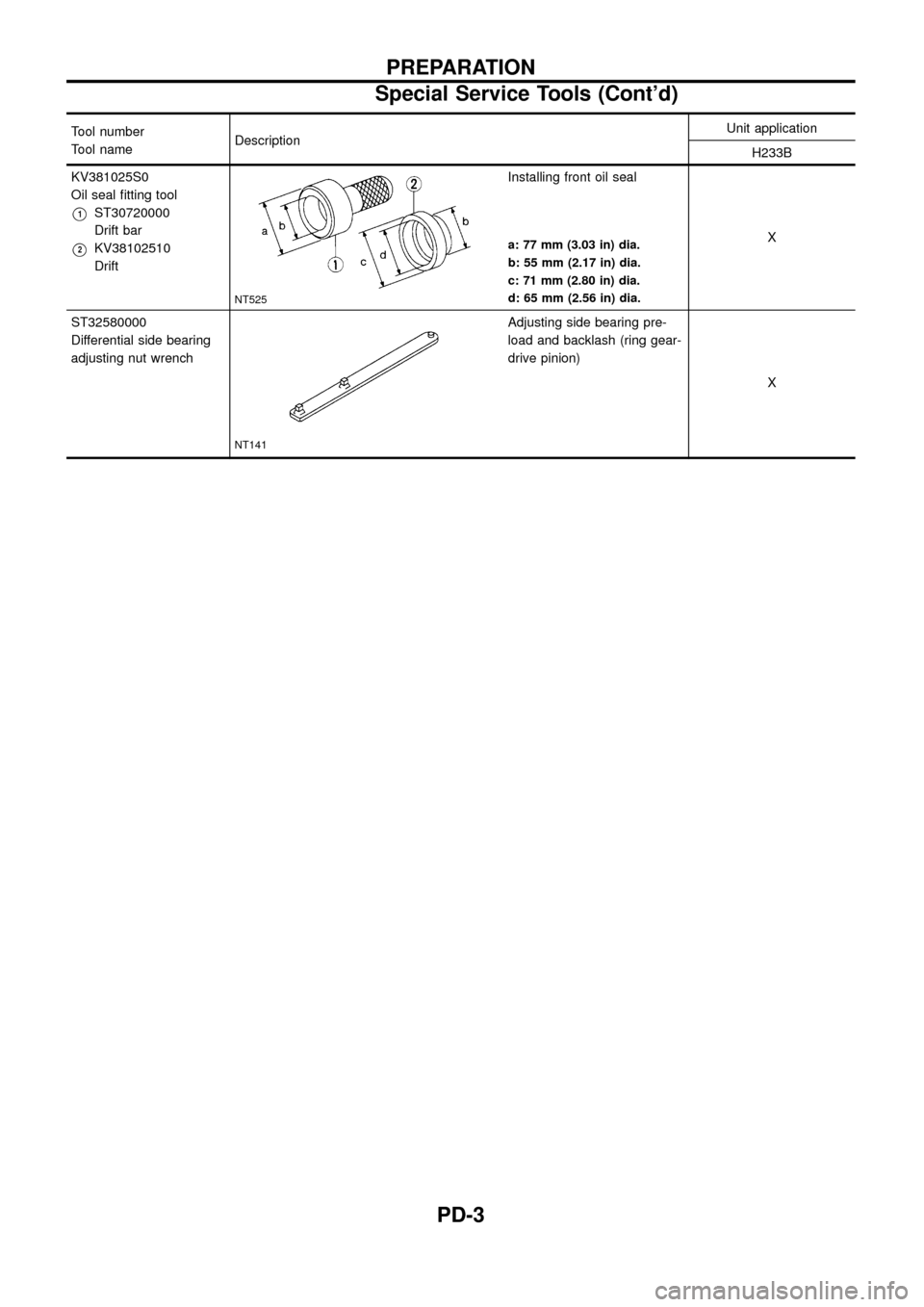
KV381025S0
Oil seal ®tting tool
V1ST30720000
Drift bar
V2KV38102510
Drift
NT525
Installing front oil seal
X
a: 77 mm (3.03 in) dia.
b: 55 mm (2.17 in) dia.
c: 71 mm (2.80 in) dia.
d: 65 mm (2.56 in) dia.
ST32580000
Differential side bearing
adjusting nut wrench
NT141
Adjusting side bearing pre-
load and backlash (ring gear-
drive pinion)
X
PREPARATION
Special Service Tools (Cont'd)
PD-3
Page 5 of 54
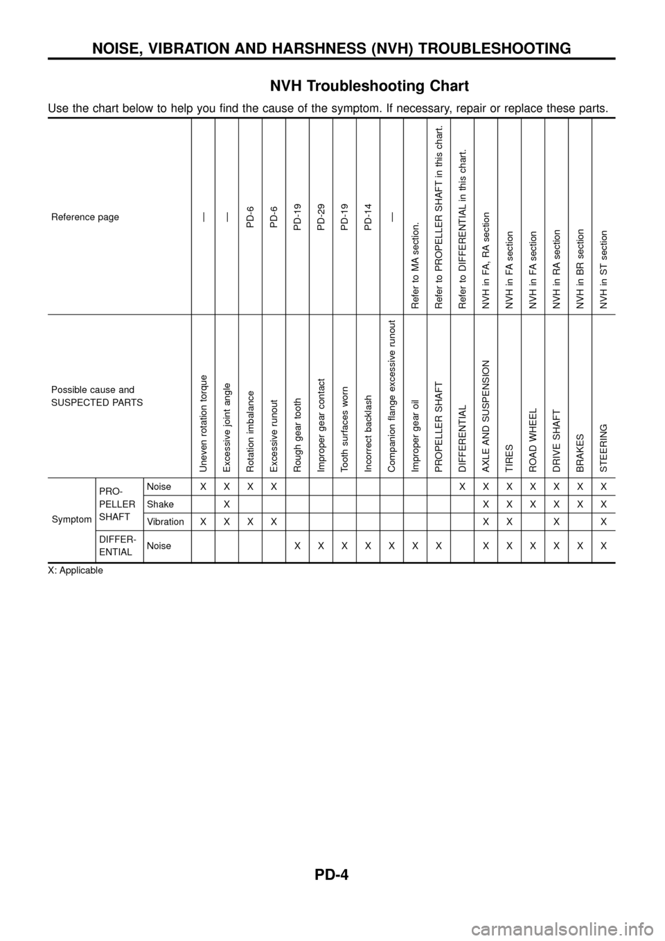
NVH Troubleshooting Chart
Use the chart below to help you ®nd the cause of the symptom. If necessary, repair or replace these parts.
Reference pageÐ
Ð
PD-6
PD-6
PD-19
PD-29
PD-19
PD-14
Ð
Refer to MA section.
Refer to PROPELLER SHAFT in this chart.
Refer to DIFFERENTIAL in this chart.
NVH in FA, RA section
NVH in FA section
NVH in FA section
NVH in RA section
NVH in BR section
NVH in ST section
Possible cause and
SUSPECTED PARTS
Uneven rotation torque
Excessive joint angle
Rotation imbalance
Excessive runout
Rough gear tooth
Improper gear contact
Tooth surfaces worn
Incorrect backlash
Companion ¯ange excessive runout
Improper gear oil
PROPELLER SHAFT
DIFFERENTIAL
AXLE AND SUSPENSION
TIRES
ROAD WHEEL
DRIVE SHAFT
BRAKES
STEERING
SymptomPRO-
PELLER
SHAFTNoiseXXXX XXXXXXX
Shake XXXXXXX
VibrationXXXX XX X X
DIFFER-
ENTIALNoiseXXXXXXX XXXXXX
X: Applicable
NOISE, VIBRATION AND HARSHNESS (NVH) TROUBLESHOOTING
PD-4
Page 6 of 54
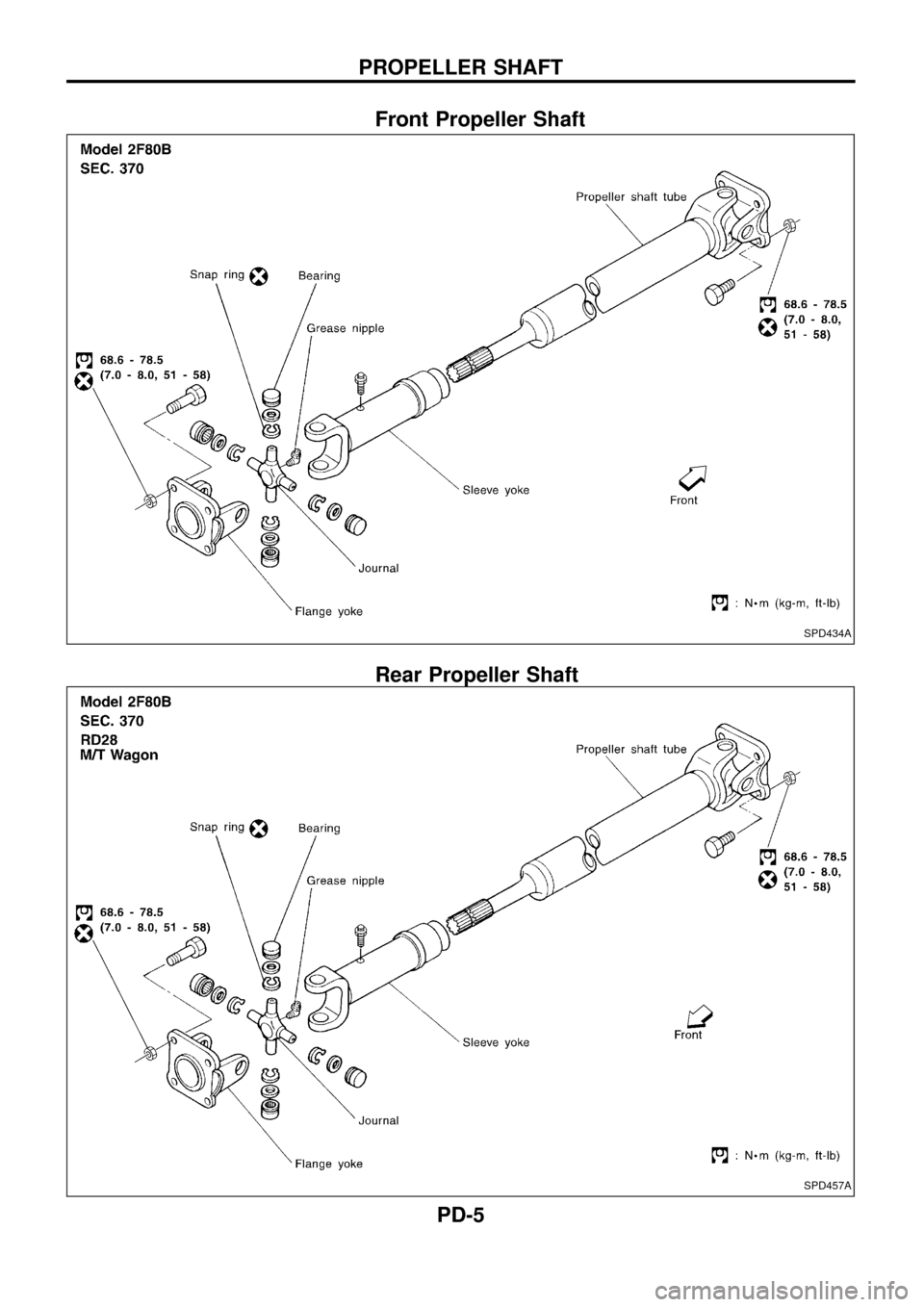
Front Propeller Shaft
Rear Propeller Shaft
SPD434A
SPD457A
PROPELLER SHAFT
PD-5
Page 7 of 54
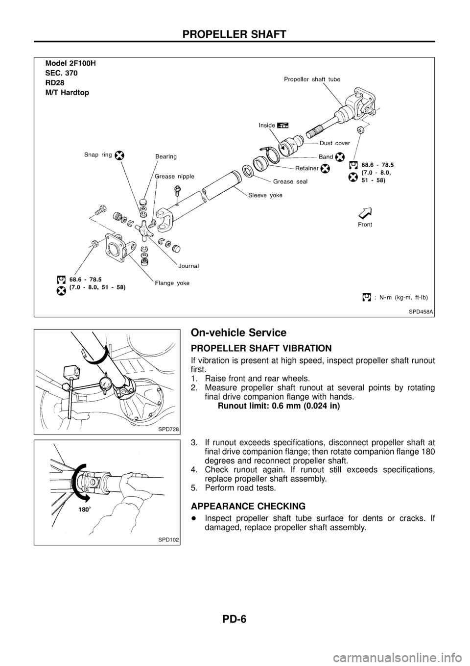
On-vehicle Service
PROPELLER SHAFT VIBRATION
If vibration is present at high speed, inspect propeller shaft runout
®rst.
1. Raise front and rear wheels.
2. Measure propeller shaft runout at several points by rotating
®nal drive companion ¯ange with hands.
Runout limit: 0.6 mm (0.024 in)
3. If runout exceeds speci®cations, disconnect propeller shaft at
®nal drive companion ¯ange; then rotate companion ¯ange 180
degrees and reconnect propeller shaft.
4. Check runout again. If runout still exceeds speci®cations,
replace propeller shaft assembly.
5. Perform road tests.
APPEARANCE CHECKING
+Inspect propeller shaft tube surface for dents or cracks. If
damaged, replace propeller shaft assembly.
SPD458A
SPD728
SPD102
PROPELLER SHAFT
PD-6
Page 8 of 54
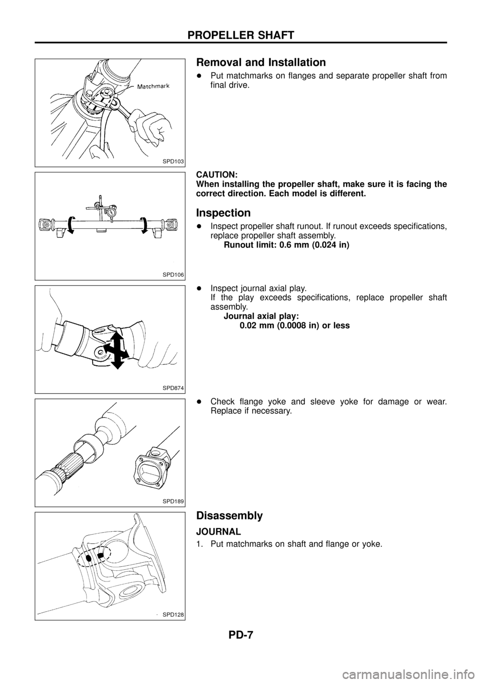
Removal and Installation
+Put matchmarks on ¯anges and separate propeller shaft from
®nal drive.
CAUTION:
When installing the propeller shaft, make sure it is facing the
correct direction. Each model is different.
Inspection
+Inspect propeller shaft runout. If runout exceeds speci®cations,
replace propeller shaft assembly.
Runout limit: 0.6 mm (0.024 in)
+Inspect journal axial play.
If the play exceeds speci®cations, replace propeller shaft
assembly.
Journal axial play:
0.02 mm (0.0008 in) or less
+Check ¯ange yoke and sleeve yoke for damage or wear.
Replace if necessary.
Disassembly
JOURNAL
1. Put matchmarks on shaft and ¯ange or yoke.
SPD103
SPD106
SPD874
SPD189
SPD128
PROPELLER SHAFT
PD-7
Page 9 of 54
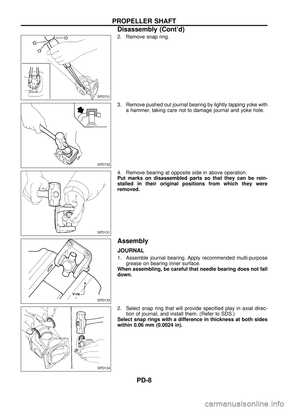
2. Remove snap ring.
3. Remove pushed out journal bearing by lightly tapping yoke with
a hammer, taking care not to damage journal and yoke hole.
4. Remove bearing at opposite side in above operation.
Put marks on disassembled parts so that they can be rein-
stalled in their original positions from which they were
removed.
Assembly
JOURNAL
1. Assemble journal bearing. Apply recommended multi-purpose
grease on bearing inner surface.
When assembling, be careful that needle bearing does not fall
down.
2. Select snap ring that will provide speci®ed play in axial direc-
tion of journal, and install them. (Refer to SDS.)
Select snap rings with a difference in thickness at both sides
within 0.06 mm (0.0024 in).
SPD731
SPD732
SPD131
SPD133
SPD134
PROPELLER SHAFT
Disassembly (Cont'd)
PD-8
Page 10 of 54
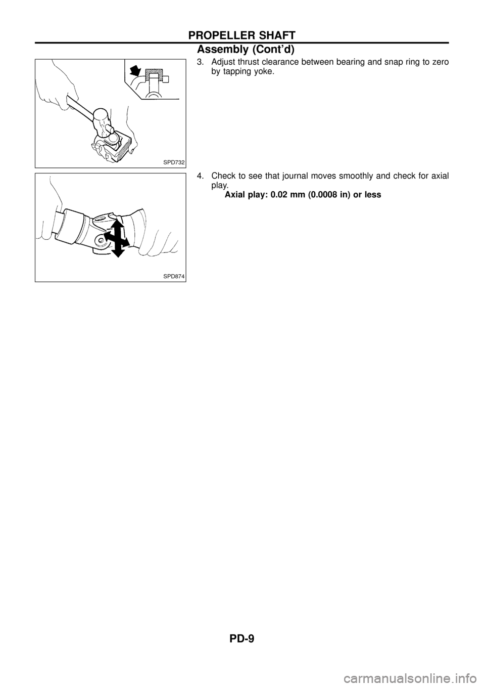
3. Adjust thrust clearance between bearing and snap ring to zero
by tapping yoke.
4. Check to see that journal moves smoothly and check for axial
play.
Axial play: 0.02 mm (0.0008 in) or less
SPD732
SPD874
PROPELLER SHAFT
Assembly (Cont'd)
PD-9