stop start NISSAN PATROL 1998 Y61 / 5.G Engine Control Workshop Manual
[x] Cancel search | Manufacturer: NISSAN, Model Year: 1998, Model line: PATROL, Model: NISSAN PATROL 1998 Y61 / 5.GPages: 192, PDF Size: 4.28 MB
Page 33 of 192
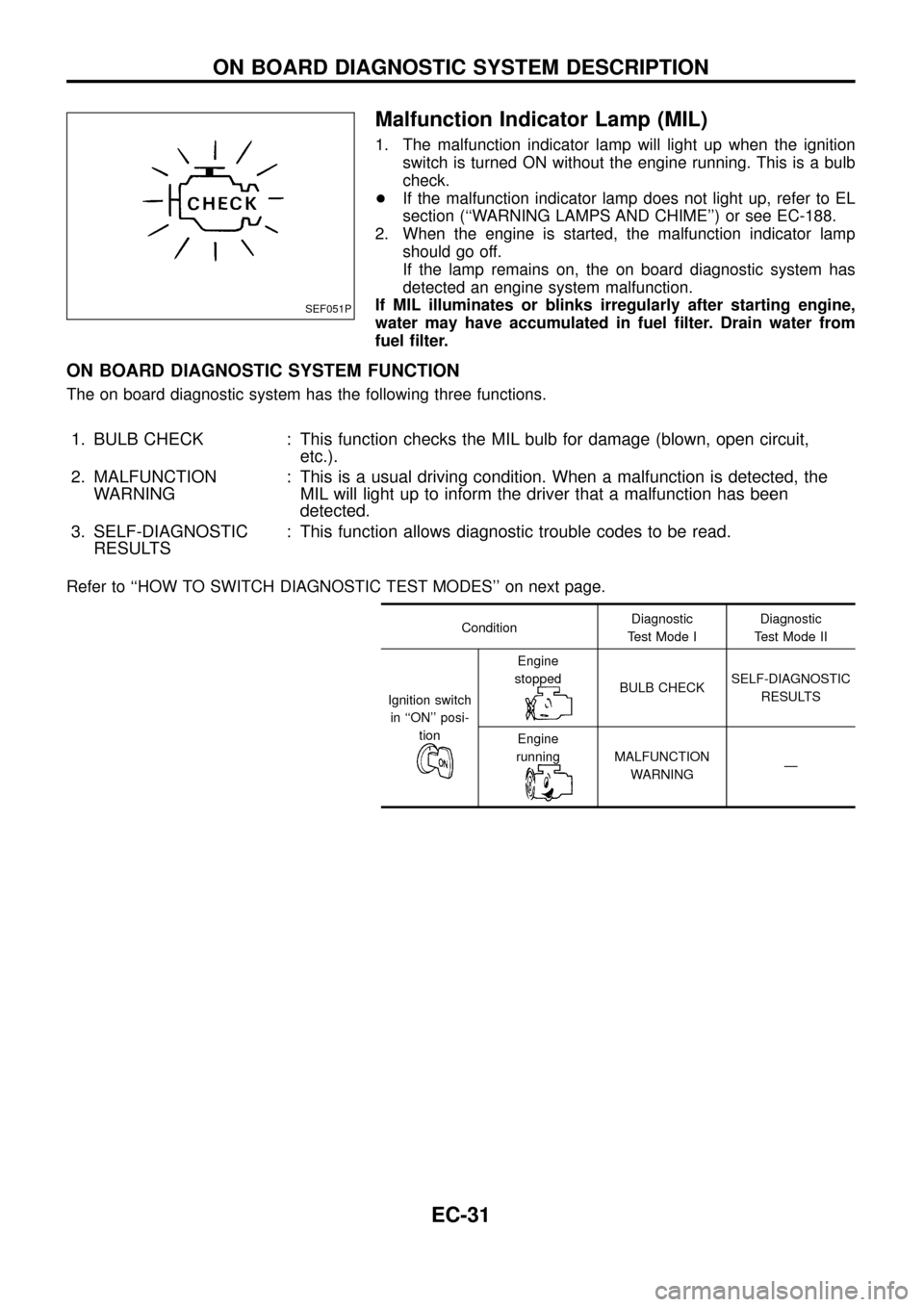
Malfunction Indicator Lamp (MIL)
1. The malfunction indicator lamp will light up when the ignition
switch is turned ON without the engine running. This is a bulb
check.
+If the malfunction indicator lamp does not light up, refer to EL
section (``WARNING LAMPS AND CHIME'') or see EC-188.
2. When the engine is started, the malfunction indicator lamp
should go off.
If the lamp remains on, the on board diagnostic system has
detected an engine system malfunction.
If MIL illuminates or blinks irregularly after starting engine,
water may have accumulated in fuel ®lter. Drain water from
fuel ®lter.
ON BOARD DIAGNOSTIC SYSTEM FUNCTION
The on board diagnostic system has the following three functions.
1. BULB CHECK : This function checks the MIL bulb for damage (blown, open circuit,
etc.).
2. MALFUNCTION
WARNING: This is a usual driving condition. When a malfunction is detected, the
MIL will light up to inform the driver that a malfunction has been
detected.
3. SELF-DIAGNOSTIC
RESULTS: This function allows diagnostic trouble codes to be read.
Refer to ``HOW TO SWITCH DIAGNOSTIC TEST MODES'' on next page.
ConditionDiagnostic
Test Mode IDiagnostic
Test Mode II
Ignition switch
in ``ON'' posi-
tion
Engine
stopped
BULB CHECKSELF-DIAGNOSTIC
RESULTS
Engine
running
MALFUNCTION
WARNINGÐ
SEF051P
ON BOARD DIAGNOSTIC SYSTEM DESCRIPTION
EC-31
Page 41 of 192
![NISSAN PATROL 1998 Y61 / 5.G Engine Control Workshop Manual Monitored item
[Unit]ECM
input
signalsMain
signalsDescription Remarks
AIR COND SIG
[ON/OFF]
jj
+Indicates [ON/OFF] condition of the air
conditioner switch as determined by the
air conditioner signal.
NISSAN PATROL 1998 Y61 / 5.G Engine Control Workshop Manual Monitored item
[Unit]ECM
input
signalsMain
signalsDescription Remarks
AIR COND SIG
[ON/OFF]
jj
+Indicates [ON/OFF] condition of the air
conditioner switch as determined by the
air conditioner signal.](/img/5/617/w960_617-40.png)
Monitored item
[Unit]ECM
input
signalsMain
signalsDescription Remarks
AIR COND SIG
[ON/OFF]
jj
+Indicates [ON/OFF] condition of the air
conditioner switch as determined by the
air conditioner signal.
IGN SW
[ON/OFF]
jj+Indicates [ON/OFF] condition from igni-
tion switch signal.
MAS AIR/FL SE [V]
jj+The signal voltage of the mass air ¯ow
sensor is displayed.+When the engine is stopped, a certain
value is indicated.
ACT INJ TIMG [É]
jj
+The actual injection timing angle deter-
mined by the ECM (an approximate
average angle between injection start
and end from TDC) is displayed.
INJ TIMG C/V [%]+Indicates the duty ratio of fuel injection
timing control valve.
DECELER F/CUT
[ON/OFF]
j
+Indicates [ON/OFF] condition from decel-
eration fuel cut signal.+When the accelerator pedal is released
quickly with engine speed at 3,000 rpm
or more, ``ON'' is displayed.
FUEL CUT S/V
[ON/OFF]
j
+The control condition of the fuel cut sole-
noid valve (determined by ECM accord-
ing to the input signal) is indicted.
+OFF ... Fuel cut solenoid valve is not
operating.
ON ... Fuel cut solenoid valve is operat-
ing.+When the fuel cut solenoid valve is not
operating, fuel is not supplied to injection
nozzles.
GLOW RLY [ON/OFF]
j
+The glow relay control condition (deter-
mined by ECM according to the input
signal) is displayed.
COOLING FAN
[LOW/HI/OFF]
j
+Indicates the control condition of the
cooling fans (determined by ECM
according to the input signal).
+LOW ... Operates at low speed.
HI ... Operates at high speed.
OFF ... Stopped.
I/C FAN RLY
[ON/OFF]
j
+Indicates the control condition of the
charge air cooler fan (determined by
ECM according to the input signals).
EGRC SOL/V A
[ON/OFF]+The control condition of the EGRC-sole-
noid valve A (determined by ECM
according to the input signal) is indi-
cated.
+OFF ... EGRC-solenoid valve A is not
operating.
ON ... EGRC-solenoid valve A is operat-
ing.
EGRC SOL/V B
[ON/OFF]+The control condition of the EGRC-sole-
noid valve B (determined by ECM
according to the input signal) is indi-
cated.
+OFF ... EGRC-solenoid valve B is not
operating.
ON ... EGRC-solenoid valve B is operat-
ing.
THROT RLY
[ON/OFF]+The control condition of the throttle con-
trol solenoid valve (determined by ECM
according to the input signal) is indi-
cated.
+OFF ... Throttle control solenoid valve is
not operating.
ON ... Throttle control solenoid valve is
operating.
ON BOARD DIAGNOSTIC SYSTEM DESCRIPTION
CONSULT (Cont'd)
EC-39
Page 45 of 192
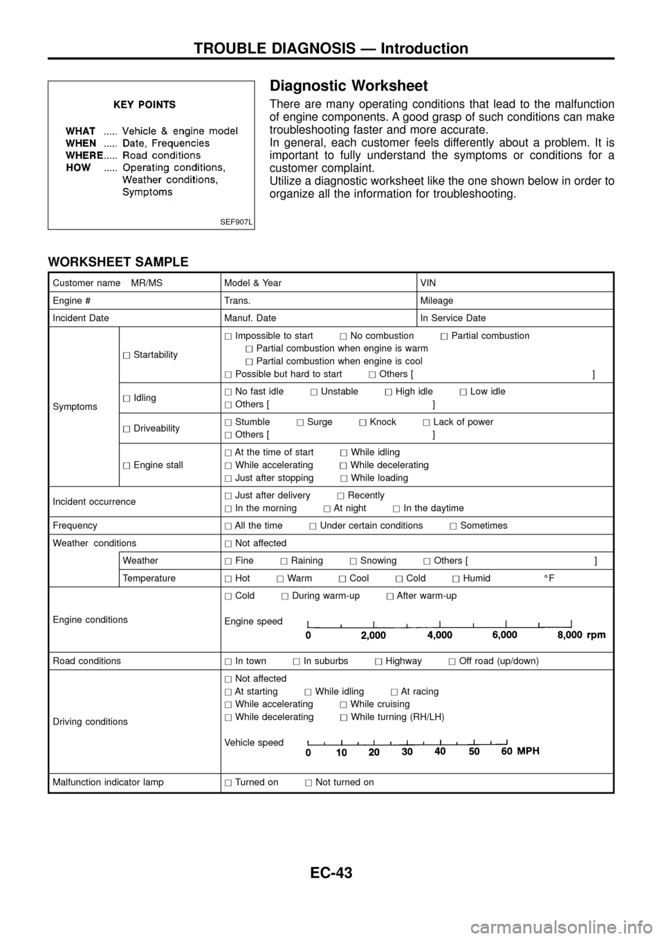
Diagnostic Worksheet
There are many operating conditions that lead to the malfunction
of engine components. A good grasp of such conditions can make
troubleshooting faster and more accurate.
In general, each customer feels differently about a problem. It is
important to fully understand the symptoms or conditions for a
customer complaint.
Utilize a diagnostic worksheet like the one shown below in order to
organize all the information for troubleshooting.
WORKSHEET SAMPLE
Customer name MR/MS Model & Year VIN
Engine # Trans. Mileage
Incident Date Manuf. Date In Service Date
SymptomshStartabilityhImpossible to starthNo combustionhPartial combustion
hPartial combustion when engine is warm
hPartial combustion when engine is cool
hPossible but hard to starthOthers [ ]
hIdlinghNo fast idlehUnstablehHigh idlehLow idle
hOthers [ ]
hDriveabilityhStumblehSurgehKnockhLack of power
hOthers [ ]
hEngine stallhAt the time of starthWhile idling
hWhile acceleratinghWhile decelerating
hJust after stoppinghWhile loading
Incident occurrencehJust after deliveryhRecently
hIn the morninghAt nighthIn the daytime
FrequencyhAll the timehUnder certain conditionshSometimes
Weather conditionshNot affected
WeatherhFinehRaininghSnowinghOthers [ ]
TemperaturehHothWarmhCoolhColdhHumid ÉF
Engine conditionshColdhDuring warm-uphAfter warm-up
Engine speed
Road conditionshIn townhIn suburbshHighwayhOff road (up/down)
Driving conditionshNot affected
hAt startinghWhile idlinghAt racing
hWhile acceleratinghWhile cruising
hWhile deceleratinghWhile turning (RH/LH)
Vehicle speed
Malfunction indicator lamphTurned onhNot turned on
SEF907L
TROUBLE DIAGNOSIS Ð Introduction
EC-43
Page 49 of 192
jA
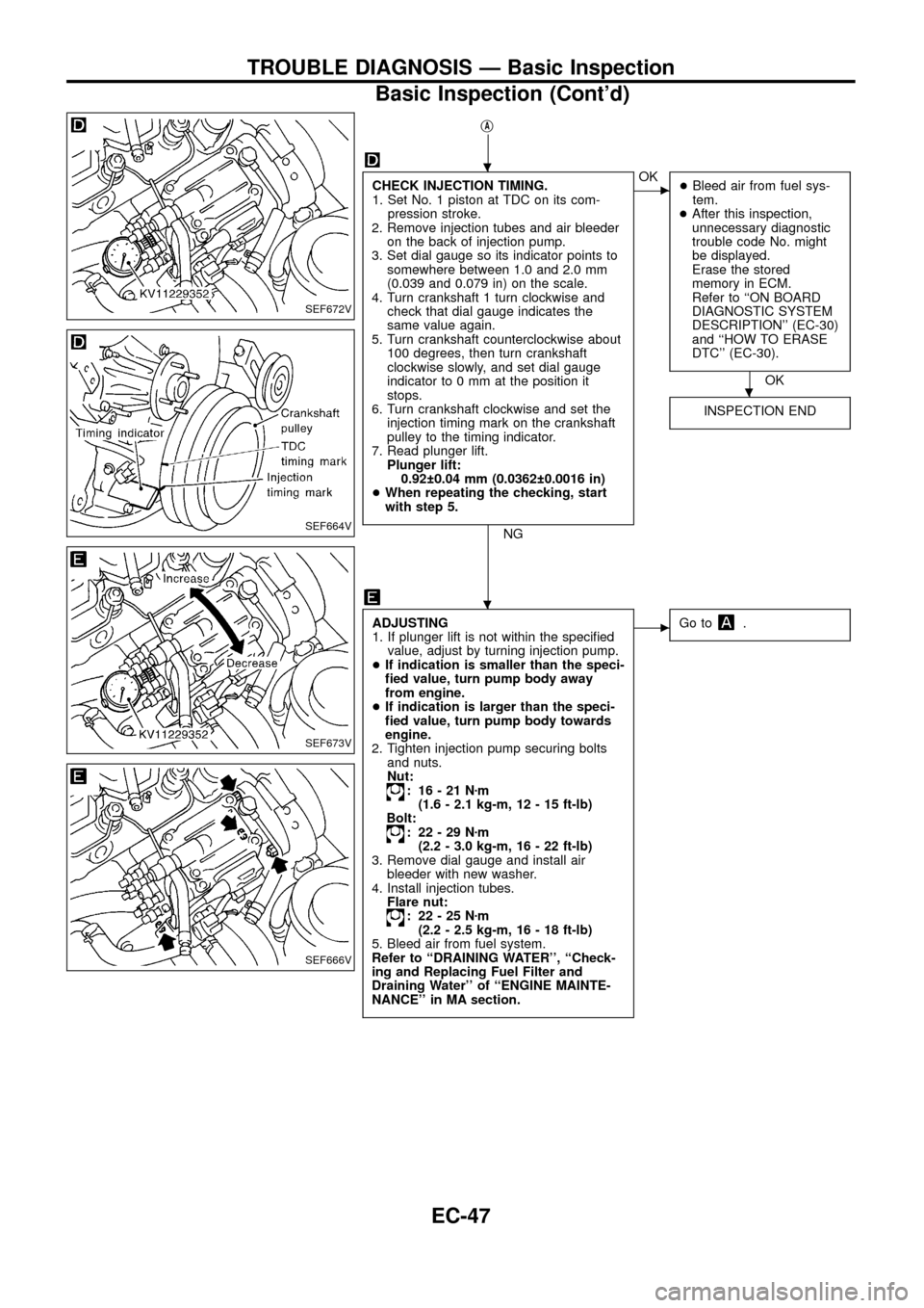
CHECK INJECTION TIMING.
1. Set No. 1 piston at TDC on its com-
pression stroke.
2. Remove injection tubes and air bleeder
on the back of injection pump.
3. Set dial gauge so its indicator points to
somewhere between 1.0 and 2.0 mm
(0.039 and 0.079 in) on the scale.
4. Turn crankshaft 1 turn clockwise and
check that dial gauge indicates the
same value again.
5. Turn crankshaft counterclockwise about
100 degrees, then turn crankshaft
clockwise slowly, and set dial gauge
indicator to 0 mm at the position it
stops.
6. Turn crankshaft clockwise and set the
injection timing mark on the crankshaft
pulley to the timing indicator.
7. Read plunger lift.
Plunger lift:
0.92 0.04 mm (0.0362 0.0016 in)
+When repeating the checking, start
with step 5.
NG
cOK
+Bleed air from fuel sys-
tem.
+After this inspection,
unnecessary diagnostic
trouble code No. might
be displayed.
Erase the stored
memory in ECM.
Refer to ``ON BOARD
DIAGNOSTIC SYSTEM
DESCRIPTION'' (EC-30)
and ``HOW TO ERASE
DTC'' (EC-30).
OK
INSPECTION END
ADJUSTING
1. If plunger lift is not within the speci®ed
value, adjust by turning injection pump.
+If indication is smaller than the speci-
®ed value, turn pump body away
from engine.
+If indication is larger than the speci-
®ed value, turn pump body towards
engine.
2. Tighten injection pump securing bolts
and nuts.
Nut:
: 16-21Nzm
(1.6 - 2.1 kg-m, 12 - 15 ft-lb)
Bolt:
: 22-29Nzm
(2.2 - 3.0 kg-m, 16 - 22 ft-lb)
3. Remove dial gauge and install air
bleeder with new washer.
4. Install injection tubes.
Flare nut:
: 22-25Nzm
(2.2 - 2.5 kg-m, 16 - 18 ft-lb)
5. Bleed air from fuel system.
Refer to ``DRAINING WATER'', ``Check-
ing and Replacing Fuel Filter and
Draining Water'' of ``ENGINE MAINTE-
NANCE'' in MA section.
cGo to.
SEF672V
SEF664V
SEF673V
SEF666V
.
.
.
TROUBLE DIAGNOSIS Ð Basic Inspection
Basic Inspection (Cont'd)
EC-47
Page 52 of 192
SYSTEM
Ð ECCS systemMalfunction
SYMPTOM
Reference page Feature of symptom
Check point
HARD/NO START/
RESTART (EXCP. HA) ENGINE STALL HESITATION/SURGING/FLAT SPOT KNOCK/DETONATION
LACK OF POWER
POOR ACCELERATION
HI IDLE
LOW IDLE
ROUGH IDLE/HUNTING
IDLING VIBRATION
SLOW/NO RETURN TO IDLE
OVERHEAT/HIGH ENGINE COOLANT TEMPERATURE
EXCESSIVE FUEL CONSUMPTION
EXCESSIVE OIL CONSUMPTION ABNORMAL SMOKE COLOR
DEAD BATTERY (UNDER CHARGE) Malfunction indicator lamp illuminates.
Can be detected by CONSULT?
Fuel cut
NO START (with ®rst ®ring) NO START (without ®rst ®ring)
HARD TO START WHEN ENGINE IS COLD
HARD TO START WHEN ENGINE IS HOT
AT IDLE
DURING DRIVING
WHEN DECELERATINGBLACK SMOKE WHITE SMOKE
Warranty symptom code AA AB AC AD AE AF AG AH AJ AK AL AM AP HAECCS
Start signal circuit open, shortjjEC-163 Start control does not function.
Neutral position switch circuitopen, shortjjj
EC-170
ground shortjj
Accelerator position switch (Idle) cir-
cuitopen, ground shortjj j
EC-165
shortjjj jjAccelerator position sensor NG
signal is output.
Accelerator position switch (Full) cir-
cuitopen, shortjjj jjEC-165
Ignition switch circuitopenj jjj
EC-63
shortEngine does not stop.
Power supply for ECM circuitopenjjj
EC-63
shortjj
Throttle control solenoid valve circuitopen, short
EC-156Does not operate.
ground shortjj jDoes not stop operating.
EGRC-solenoid valve A, B circuitopen, short
EC-156
ground shortjDoes not stop operating.
Glow relay circuitopenjjjjj
EC-151Glow lamp does not turn on.
shortGlow lamp does not turn off.
ECCS relay (Self-shutoff) circuitopenjjjj
EC-63
shortjjGround short makes engine
unable to stop.
ECM, Connector circuit open, shortjjjjjjjjjjjjj jjjjjjjjjjjjEC-111
Air conditioner relay circuitopen
EC-187Air conditioner does not operate.
shortAir conditioner does not stop
operating.
Air conditioner switch circuitopen, ground short
EC-187Air conditioner does not stop
operating.
shortAir conditioner does not work.
TROUBLE DIAGNOSIS Ð General Description
Symptom Matrix Chart (Cont'd)
EC-50
Page 53 of 192
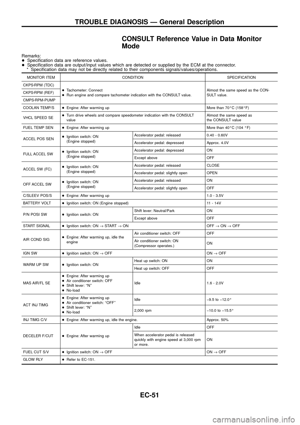
CONSULT Reference Value in Data Monitor
Mode
Remarks:
+Speci®cation data are reference values.
+Speci®cation data are output/input values which are detected or supplied by the ECM at the connector.
* Speci®cation data may not be directly related to their components signals/values/operations.
MONITOR ITEM CONDITION SPECIFICATION
CKPSzRPM (TDC)
+Tachometer: Connect
+Run engine and compare tachometer indication with the CONSULT value.Almost the same speed as the CON-
SULT value. CKPSzRPM (REF)
CMPSzRPM-PUMP
COOLAN TEMP/S+Engine: After warming up More than 70ÉC (158ÉF)
VHCL SPEED SE+Turn drive wheels and compare speedometer indication with the CONSULT
valueAlmost the same speed as
the CONSULT value
FUEL TEMP SEN+Engine: After warming up More than 40ÉC (104 ÉF)
ACCEL POS SEN+Ignition switch: ON
(Engine stopped)Accelerator pedal: released 0.40 - 0.60V
Accelerator pedal: depressed Approx. 4.0V
FULL ACCEL SW+Ignition switch: ON
(Engine stopped)Accelerator pedal: depressed ON
Except above OFF
ACCEL SW (FC)+Ignition switch: ON
(Engine stopped)Accelerator pedal: released CLOSE
Accelerator pedal: slightly open OPEN
OFF ACCEL SW+Ignition switch: ON
(Engine stopped)Accelerator pedal: released ON
Accelerator pedal: slightly open OFF
C/SLEEV POS/S+Engine: After warming up 1.0 - 3.5V
BATTERY VOLT+Ignition switch: ON (Engine stopped) 11 - 14V
P/N POSI SW+Ignition switch: ONShift lever: Neutral/Park ON
Except above OFF
START SIGNAL+Ignition switch: ON®START®ON OFF®ON®OFF
AIR COND SIG+Engine: After warming up, idle the
engineAir conditioner switch: OFF OFF
Air conditioner switch: ON
(Compressor operates.)ON
IGN SW+Ignition switch: ON®OFF ON®OFF
WARM UP SW+Ignition switch: ONHeat up switch: ON ON
Heat up switch: OFF OFF
MAS AIR/FL SE+Engine: After warming up
+Air conditioner switch: OFF
+Shift lever: ``N''
+No-loadIdle 1.6 - 2.0V
ACT INJ TIMG+Engine: After warming up
+Air conditioner switch: ``OFF''
+Shift lever: ``N''
+No-loadIdle þ9.5 to þ12.0É
2,000 rpm þ10.0 to þ15.5É
INJ TIMG C/V+Engine: After warming up, idle the engine. Approx. 50%
DECELER F/CUT+Engine: After warming upIdle OFF
When accelerator pedal is released
quickly with engine speed at 3,000 rpm
or more.ON
FUEL CUT S/V+Ignition switch: ON®OFF ON®OFF
GLOW RLY+Refer to EC-151.
TROUBLE DIAGNOSIS Ð General Description
EC-51
Page 68 of 192
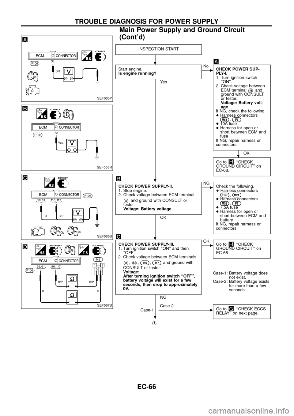
INSPECTION START
Start engine.
Is engine running?
Ye s
cNo
CHECK POWER SUP-
PLY-I.
1. Turn ignition switch
``ON''.
2. Check voltage between
ECM terminal
V38and
ground with CONSULT
or tester.
Voltage: Battery volt-
age
If NG, check the following.
+Harness connectors
M51,F6+10A fuse
+Harness for open or
short between ECM and
fuse
If NG, repair harness or
connectors.
OK
Go to
``CHECK
GROUND CIRCUIT'' on
EC-68.
CHECK POWER SUPPLY-II.
1. Stop engine.
2. Check voltage between ECM terminal
V70and ground with CONSULT or
tester.
Voltage: Battery voltage
OK
cNG
Check the following.
+Harness connectors
E127,M21+Harness connectorsM52,F7+7.5A fuse
+Harness for open or
short between ECM and
battery
If NG, repair harness or
connectors.
CHECK POWER SUPPLY-III.
1. Turn ignition switch ``ON'' and then
``OFF''.
2. Check voltage between ECM terminals
V56,V61,11 6,11 7and ground with
CONSULT or tester.
Voltage:
After turning ignition switch ``OFF'',
battery voltage will exist for a few
seconds, then drop to approximately
0V.
NG
cOK
Go to``CHECK
GROUND CIRCUIT'' on
EC-68.
Case-1: Battery voltage does
not exist.
Case-2: Battery voltage exists
for more than a few
seconds.
Case-1
cCase-2
Go to``CHECK ECCS
RELAY'' on next page.
jA
SEF065P
SEF056R
SEF566S
SEF567S
.
.
.
.
.
TROUBLE DIAGNOSIS FOR POWER SUPPLY
Main Power Supply and Ground Circuit
(Cont'd)
EC-66
Page 80 of 192
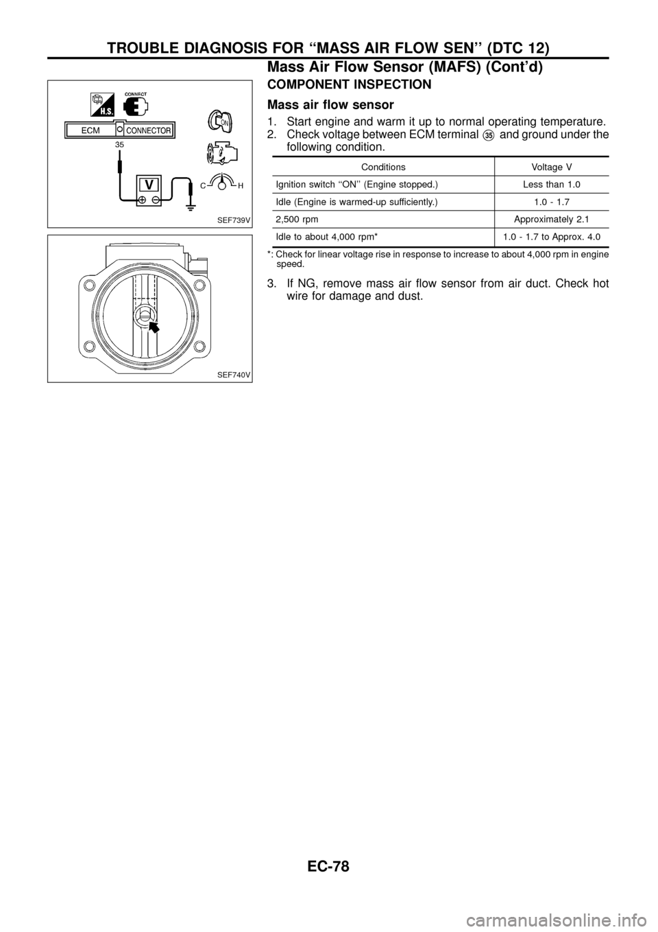
COMPONENT INSPECTION
Mass air ¯ow sensor
1. Start engine and warm it up to normal operating temperature.
2. Check voltage between ECM terminal
V35and ground under the
following condition.
Conditions Voltage V
Ignition switch ``ON'' (Engine stopped.) Less than 1.0
Idle (Engine is warmed-up sufficiently.) 1.0 - 1.7
2,500 rpm Approximately 2.1
Idle to about 4,000 rpm* 1.0 - 1.7 to Approx. 4.0
*: Check for linear voltage rise in response to increase to about 4,000 rpm in engine
speed.
3. If NG, remove mass air ¯ow sensor from air duct. Check hot
wire for damage and dust.
SEF739V
SEF740V
TROUBLE DIAGNOSIS FOR ``MASS AIR FLOW SEN'' (DTC 12)
Mass Air Flow Sensor (MAFS) (Cont'd)
EC-78
Page 180 of 192
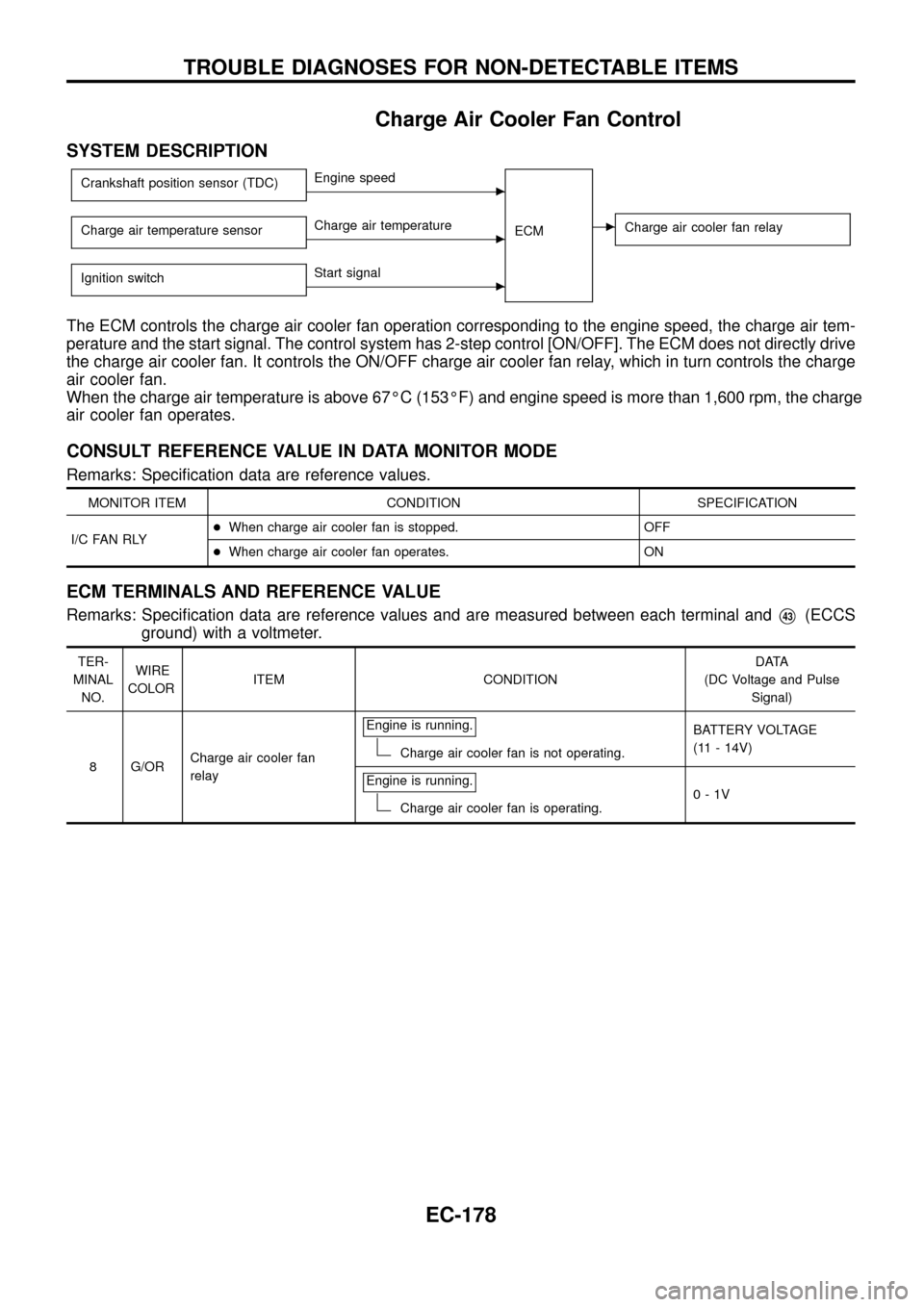
Charge Air Cooler Fan Control
SYSTEM DESCRIPTION
Crankshaft position sensor (TDC)cEngine speed
ECM
cCharge air cooler fan relayCharge air temperature sensorcCharge air temperature
Ignition switch
cStart signal
The ECM controls the charge air cooler fan operation corresponding to the engine speed, the charge air tem-
perature and the start signal. The control system has 2-step control [ON/OFF]. The ECM does not directly drive
the charge air cooler fan. It controls the ON/OFF charge air cooler fan relay, which in turn controls the charge
air cooler fan.
When the charge air temperature is above 67ÉC (153ÉF) and engine speed is more than 1,600 rpm, the charge
air cooler fan operates.
CONSULT REFERENCE VALUE IN DATA MONITOR MODE
Remarks: Speci®cation data are reference values.
MONITOR ITEM CONDITION SPECIFICATION
I/C FAN RLY+When charge air cooler fan is stopped. OFF
+When charge air cooler fan operates. ON
ECM TERMINALS AND REFERENCE VALUE
Remarks: Speci®cation data are reference values and are measured between each terminal andV43(ECCS
ground) with a voltmeter.
TER-
MINAL
NO.WIRE
COLORITEM CONDITIONDATA
(DC Voltage and Pulse
Signal)
8 G/ORCharge air cooler fan
relayEngine is running.
Charge air cooler fan is not operating.BATTERY VOLTAGE
(11 - 14V)
Engine is running.
Charge air cooler fan is operating.0-1V
TROUBLE DIAGNOSES FOR NON-DETECTABLE ITEMS
EC-178
Page 182 of 192
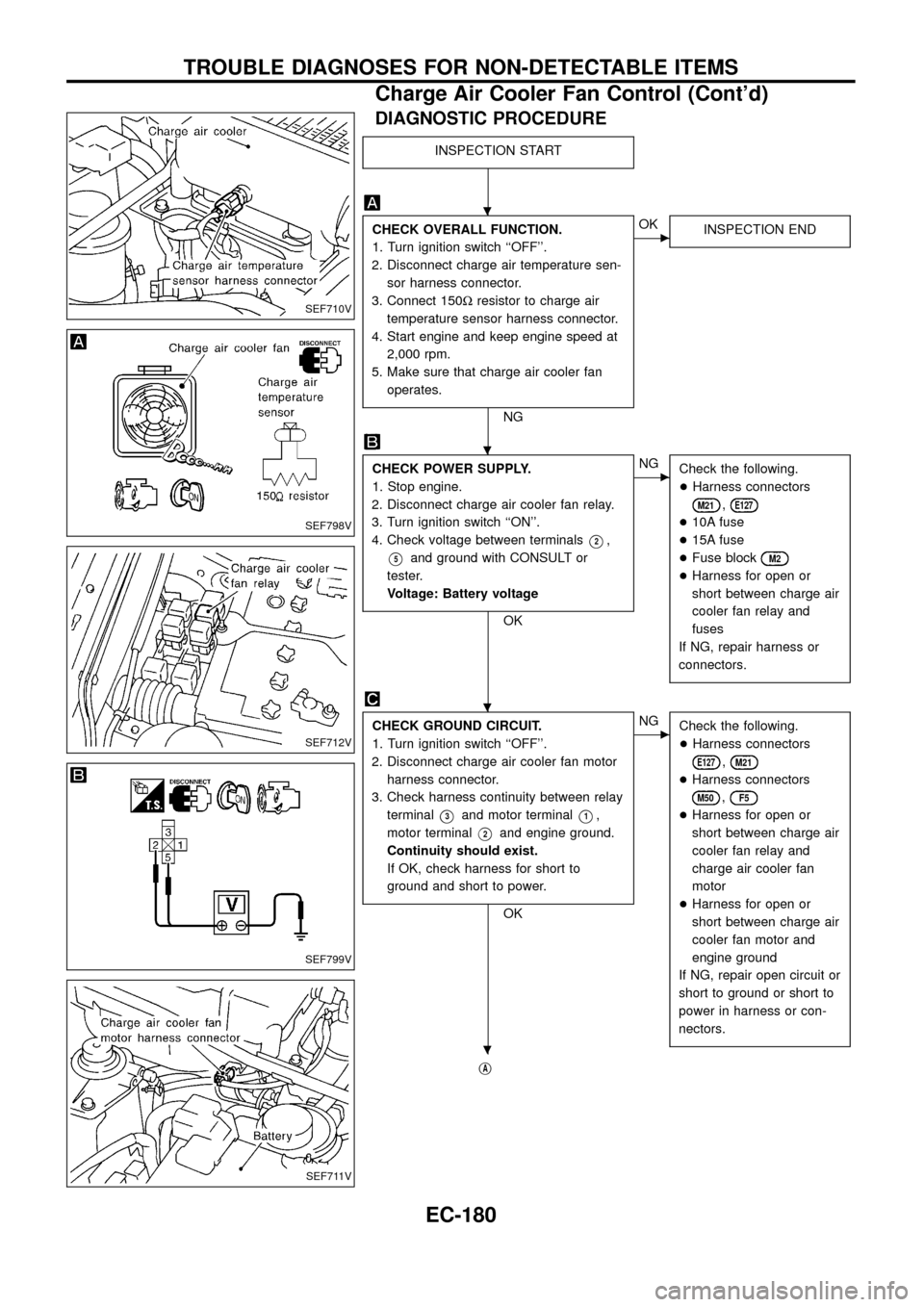
DIAGNOSTIC PROCEDURE
INSPECTION START
CHECK OVERALL FUNCTION.
1. Turn ignition switch ``OFF''.
2. Disconnect charge air temperature sen-
sor harness connector.
3. Connect 150Wresistor to charge air
temperature sensor harness connector.
4. Start engine and keep engine speed at
2,000 rpm.
5. Make sure that charge air cooler fan
operates.
NG
cOK
INSPECTION END
CHECK POWER SUPPLY.
1. Stop engine.
2. Disconnect charge air cooler fan relay.
3. Turn ignition switch ``ON''.
4. Check voltage between terminals
V2,
V5and ground with CONSULT or
tester.
Voltage: Battery voltage
OK
cNG
Check the following.
+Harness connectors
M21,E127
+10A fuse
+15A fuse
+Fuse block
M2
+Harness for open or
short between charge air
cooler fan relay and
fuses
If NG, repair harness or
connectors.
CHECK GROUND CIRCUIT.
1. Turn ignition switch ``OFF''.
2. Disconnect charge air cooler fan motor
harness connector.
3. Check harness continuity between relay
terminal
V3and motor terminalV1,
motor terminal
V2and engine ground.
Continuity should exist.
If OK, check harness for short to
ground and short to power.
OK
cNG
Check the following.
+Harness connectors
E127,M21
+Harness connectors
M50,F5
+Harness for open or
short between charge air
cooler fan relay and
charge air cooler fan
motor
+Harness for open or
short between charge air
cooler fan motor and
engine ground
If NG, repair open circuit or
short to ground or short to
power in harness or con-
nectors.
jA
SEF710V
SEF798V
SEF712V
SEF799V
SEF711V
.
.
.
.
TROUBLE DIAGNOSES FOR NON-DETECTABLE ITEMS
Charge Air Cooler Fan Control (Cont'd)
EC-180