NISSAN PATROL 1998 Y61 / 5.G Engine Control Workshop Manual
Manufacturer: NISSAN, Model Year: 1998, Model line: PATROL, Model: NISSAN PATROL 1998 Y61 / 5.GPages: 192, PDF Size: 4.28 MB
Page 1 of 192
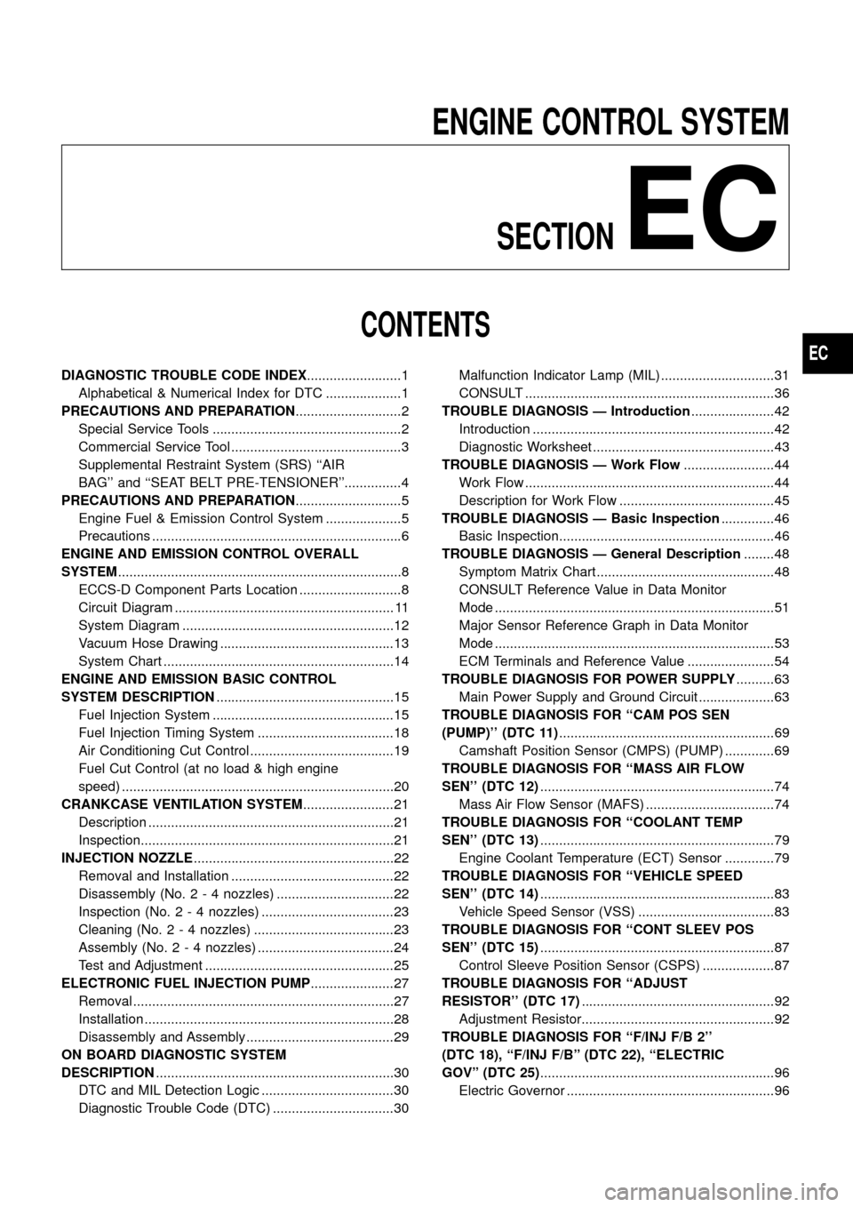
ENGINE CONTROL SYSTEMSECTION
EC
CONTENTS
DIAGNOSTIC TROUBLE CODE INDEX .........................1
Alphabetical & Numerical Index for DTC ....................1
PRECAUTIONS AND PREPARATION ............................2
Special Service Tools ..................................................2
Commercial Service Tool .............................................3
Supplemental Restraint System (SRS) ``AIR
BAG'' and ``SEAT BELT PRE-TENSIONER''...............4
PRECAUTIONS AND PREPARATION ............................5
Engine Fuel & Emission Control System ....................5
Precautions ..................................................................6
ENGINE AND EMISSION CONTROL OVERALL
SYSTEM ........................................................................\
...8
ECCS-D Component Parts Location ...........................8
Circuit Diagram .......................................................... 11
System Diagram ........................................................12
Vacuum Hose Drawing ..............................................13
System Chart .............................................................14
ENGINE AND EMISSION BASIC CONTROL
SYSTEM DESCRIPTION ...............................................15
Fuel Injection System ................................................15
Fuel Injection Timing System ....................................18
Air Conditioning Cut Control ......................................19
Fuel Cut Control (at no load & high engine
speed) ........................................................................\
20
CRANKCASE VENTILATION SYSTEM ........................21
Description .................................................................21
Inspection...................................................................21
INJECTION NOZZLE .....................................................22
Removal and Installation ...........................................22
Disassembly (No. 2 - 4 nozzles) ...............................22
Inspection (No. 2 - 4 nozzles) ...................................23
Cleaning (No. 2 - 4 nozzles) .....................................23
Assembly (No. 2 - 4 nozzles) ....................................24
Test and Adjustment ..................................................25
ELECTRONIC FUEL INJECTION PUMP ......................27
Removal .....................................................................27
Installation ..................................................................28
Disassembly and Assembly .......................................29
ON BOARD DIAGNOSTIC SYSTEM
DESCRIPTION ...............................................................30
DTC and MIL Detection Logic ...................................30
Diagnostic Trouble Code (DTC) ................................30 Malfunction Indicator Lamp (MIL) ..............................31
CONSULT ..................................................................36
TROUBLE DIAGNOSIS Ð Introduction ......................42
Introduction ................................................................42
Diagnostic Worksheet ................................................43
TROUBLE DIAGNOSIS Ð Work Flow ........................44
Work Flow ..................................................................44
Description for Work Flow .........................................45
TROUBLE DIAGNOSIS Ð Basic Inspection ..............46
Basic Inspection.........................................................46
TROUBLE DIAGNOSIS Ð General Description ........48
Symptom Matrix Chart ...............................................48
CONSULT Reference Value in Data Monitor
Mode ........................................................................\
..51
Major Sensor Reference Graph in Data Monitor
Mode ........................................................................\
..53
ECM Terminals and Reference Value .......................54
TROUBLEDIAGNOSISFORPOWERSUPPLY ..........63
MainPowerSupplyandGroundCircuit....................63
TROUBLE DIAGNOSIS FOR ``CAM POS SEN
(PUMP)''(DTC11) .........................................................69
CamshaftPositionSensor(CMPS)(PUMP).............69
TROUBLEDIAGNOSISFOR``MASSAIRFLOW
SEN''(DTC12) ..............................................................74
MassAirFlowSensor(MAFS)..................................74
TROUBLEDIAGNOSISFOR``COOLANTTEMP
SEN''(DTC13) ..............................................................79
EngineCoolantTemperature(ECT)Sensor.............79
TROUBLEDIAGNOSISFOR``VEHICLESPEED
SEN''(DTC14) ..............................................................83
VehicleSpeedSensor(VSS)....................................83
TROUBLEDIAGNOSISFOR``CONTSLEEVPOS
SEN''(DTC15) ..............................................................87
ControlSleevePositionSensor(CSPS)...................87
TROUBLEDIAGNOSISFOR``ADJUST
RESISTOR''(DTC17) ...................................................92
AdjustmentResistor...................................................92
TROUBLEDIAGNOSISFOR``F/INJF/B2''
(DTC18),``F/INJF/B''(DTC22),``ELECTRIC
GOV''(DTC25) ..............................................................96
ElectricGovernor.......................................................96
EC
Page 2 of 192
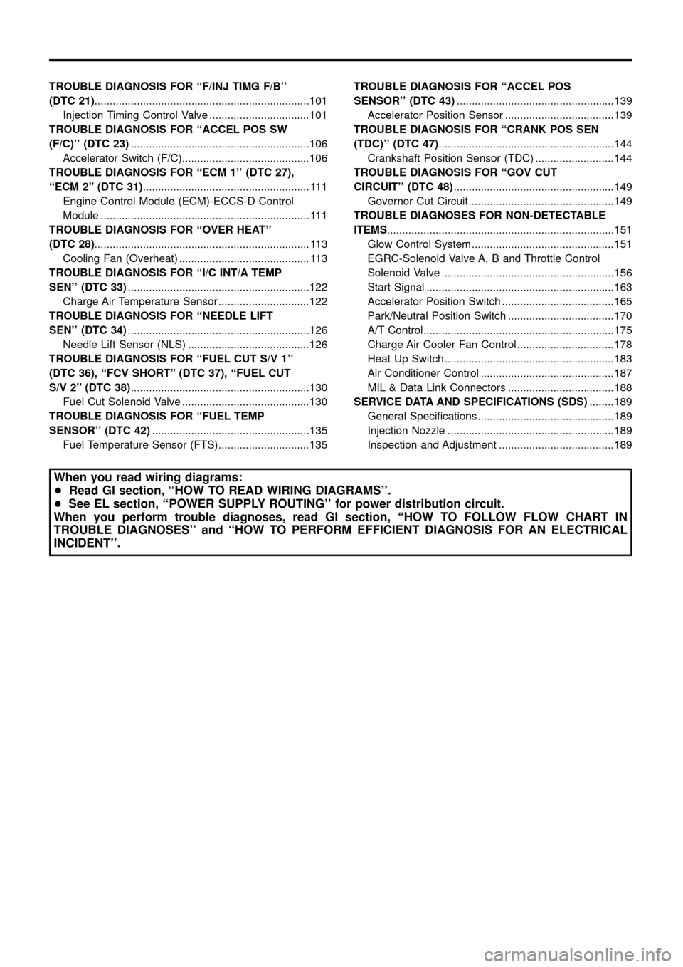
TROUBLEDIAGNOSISFOR``F/INJTIMGF/B''
(DTC21).......................................................................101
InjectionTimingControlValve.................................101
TROUBLEDIAGNOSISFOR``ACCELPOSSW
(F/C)''(DTC23) ...........................................................106
AcceleratorSwitch(F/C)..........................................106
TROUBLEDIAGNOSISFOR``ECM1''(DTC27),
``ECM2''(DTC31) .......................................................111
EngineControlModule(ECM)-ECCS-DControl
Module.....................................................................111
TROUBLEDIAGNOSISFOR``OVERHEAT''
(DTC28) .......................................................................113
CoolingFan(Overheat)...........................................113
TROUBLEDIAGNOSISFOR``I/CINT/ATEMP
SEN''(DTC33) ............................................................122
ChargeAirTemperatureSensor..............................122
TROUBLEDIAGNOSISFOR``NEEDLELIFT
SEN''(DTC34) ............................................................126
NeedleLiftSensor(NLS)........................................126
TROUBLE DIAGNOSIS FOR ``FUEL CUT S/V 1''
(DTC 36), ``FCV SHORT'' (DTC 37), ``FUEL CUT
S/V2''(DTC38) ...........................................................130
FuelCutSolenoidValve..........................................130
TROUBLE DIAGNOSIS FOR ``FUEL TEMP
SENSOR''(DTC42) ....................................................135
FuelTemperatureSensor(FTS)..............................135 TROUBLE DIAGNOSIS FOR ``ACCEL POS
SENSOR''(DTC43)
....................................................139
AcceleratorPositionSensor....................................139
TROUBLE DIAGNOSIS FOR ``CRANK POS SEN
(TDC)''(DTC47) ..........................................................144
CrankshaftPositionSensor(TDC)..........................144
TROUBLEDIAGNOSISFOR``GOVCUT
CIRCUIT''(DTC48) .....................................................149
GovernorCutCircuit................................................149
TROUBLEDIAGNOSESFORNON-DETECTABLE
ITEMS ........................................................................\
...151
GlowControlSystem...............................................151
EGRC-SolenoidValveA,BandThrottleControl
SolenoidValve.........................................................156
StartSignal..............................................................163
AcceleratorPositionSwitch.....................................165
Park/NeutralPositionSwitch...................................170
A/TControl...............................................................175
ChargeAirCoolerFanControl................................178
HeatUpSwitch........................................................183
AirConditionerControl............................................187
MIL&DataLinkConnectors...................................188
SERVICEDATAANDSPECIFICATIONS(SDS) ........189
GeneralSpeci®cations.............................................189
InjectionNozzle.......................................................189
InspectionandAdjustment......................................189
When you read wiring diagrams:
+ Read GI section, ``HOW TO READ WIRING DIAGRAMS''.
+ See EL section, ``POWER SUPPLY ROUTING'' for power distribution circuit.
When you perform trouble diagnoses, read GI section, ``HOW TO FOLLOW FLOW CHART IN
TROUBLE DIAGNOSES'' and ``HOW TO PERFORM EFFICIENT DIAGNOSIS FOR AN ELECTRICAL
INCIDENT''.
Page 3 of 192
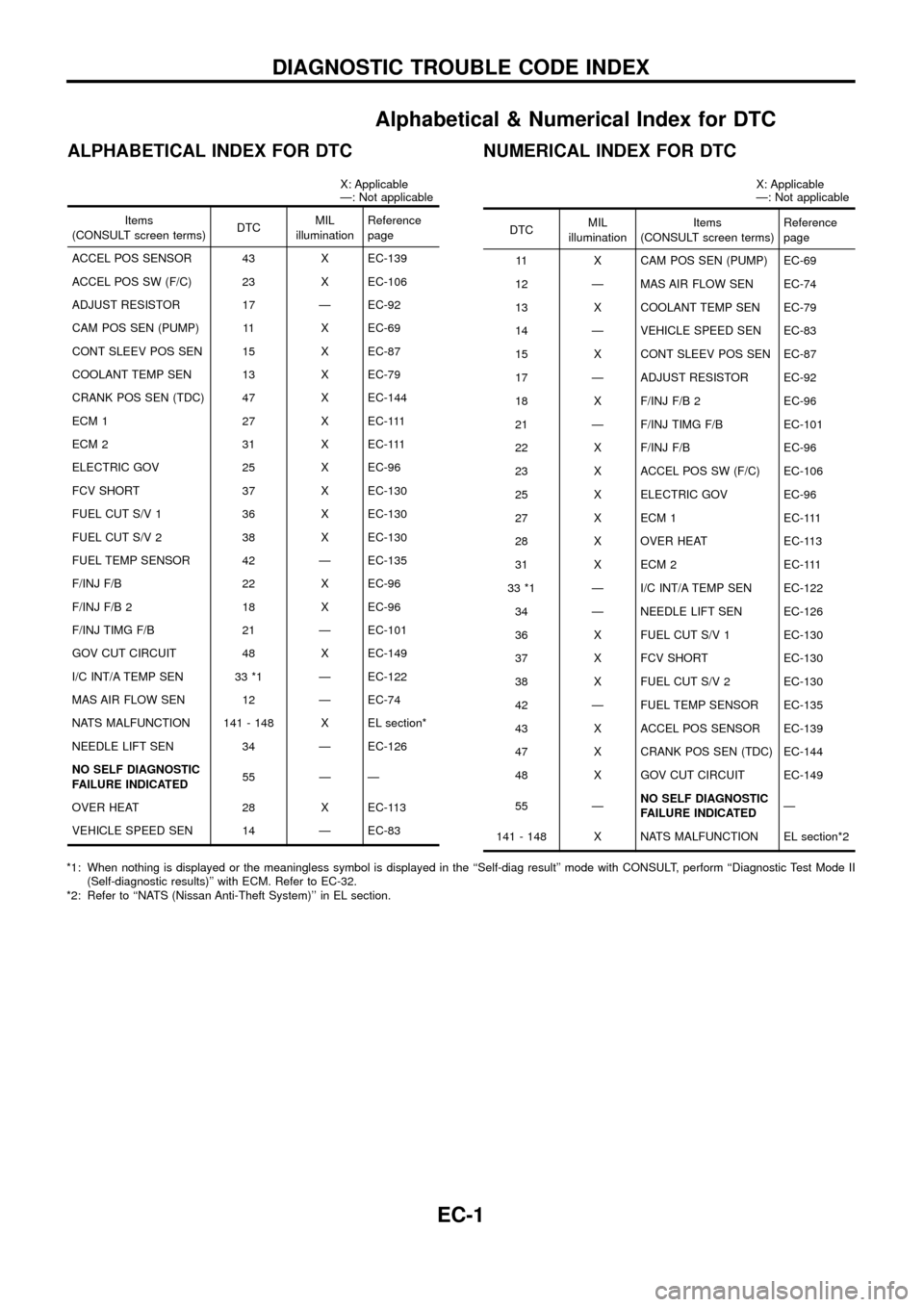
Alphabetical & Numerical Index for DTC
ALPHABETICAL INDEX FOR DTC
X: Applicable
Ð: Not applicable
Items
(CONSULT screen terms) DTCMIL
illumination Reference
page
ACCEL POS SENSOR 43 X EC-139
ACCEL POS SW (F/C) 23 X EC-106
ADJUST RESISTOR 17 Ð EC-92
CAM POS SEN (PUMP) 11 X EC-69
CONT SLEEV POS SEN 15 X EC-87
COOLANT TEMP SEN 13 X EC-79
CRANK POS SEN (TDC) 47 X EC-144
ECM 1 27 X EC-111
ECM 2 31 X EC-111
ELECTRIC GOV 25 X EC-96
FCV SHORT 37 X EC-130
FUEL CUT S/V 1 36 X EC-130
FUEL CUT S/V 2 38 X EC-130
FUEL TEMP SENSOR 42 Ð EC-135
F/INJ F/B 22 X EC-96
F/INJ F/B 2 18 X EC-96
F/INJ TIMG F/B 21 Ð EC-101
GOV CUT CIRCUIT 48 X EC-149
I/C INT/A TEMP SEN 33 *1 Ð EC-122
MAS AIR FLOW SEN 12 Ð EC-74
NATS MALFUNCTION 141 - 148 X EL section*
NEEDLE LIFT SEN 34 Ð EC-126
NO SELF DIAGNOSTIC
FAILURE INDICATED 55 Ð Ð
OVER HEAT 28 X EC-113
VEHICLE SPEED SEN 14 Ð EC-83
NUMERICAL INDEX FOR DTC
X: Applicable
Ð: Not applicable
DTC MIL
illumination Items
(CONSULT screen terms) Reference
page
11 X CAM POS SEN (PUMP) EC-69
12 Ð MAS AIR FLOW SEN EC-74
13 X COOLANT TEMP SEN EC-79
14 Ð VEHICLE SPEED SEN EC-83
15 X CONT SLEEV POS SEN EC-87
17 Ð ADJUST RESISTOR EC-92
18 X F/INJ F/B 2 EC-96
21 Ð F/INJ TIMG F/B EC-101
22 X F/INJ F/B EC-96
23 X ACCEL POS SW (F/C) EC-106
25 X ELECTRIC GOV EC-96
27 X ECM 1 EC-111
28 X OVER HEAT EC-113
31 X ECM 2 EC-111
33 *1 Ð I/C INT/A TEMP SEN EC-122 34 Ð NEEDLE LIFT SEN EC-126
36 X FUEL CUT S/V 1 EC-130
37 X FCV SHORT EC-130
38 X FUEL CUT S/V 2 EC-130
42 Ð FUEL TEMP SENSOR EC-135
43 X ACCEL POS SENSOR EC-139
47 X CRANK POS SEN (TDC) EC-144
48 X GOV CUT CIRCUIT EC-149
55 Ð NO SELF DIAGNOSTIC
FAILURE INDICATED Ð
141 - 148 X NATS MALFUNCTION EL section*2
*1: When nothing is displayed or the meaningless symbol is displayed in the ``Self-diag result'' mode with CONSULT, perform ``Diagnostic Test Mode II (Self-diagnostic results)'' with ECM. Refer to EC-32.
*2: Refer to ``NATS (Nissan Anti-Theft System)'' in EL section.
DIAGNOSTIC TROUBLE CODE INDEX
EC-1
Page 4 of 192
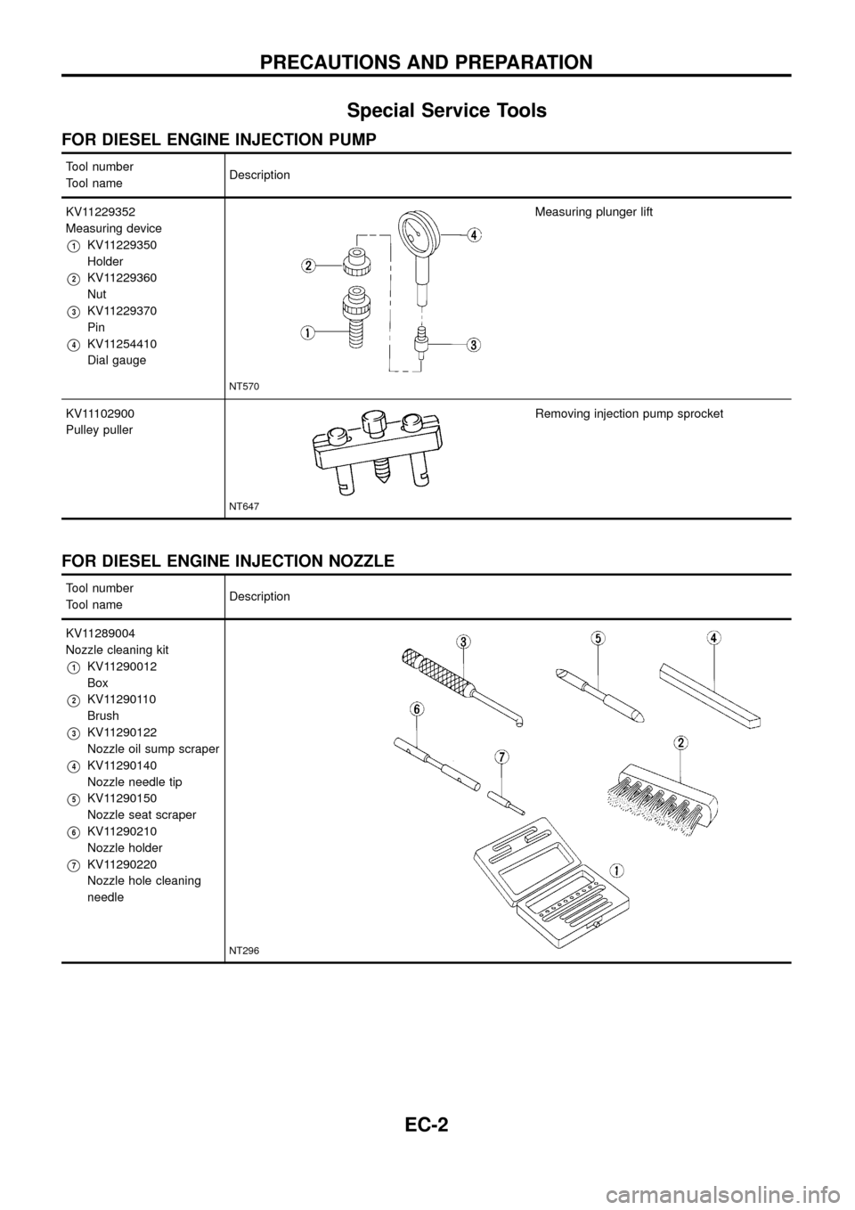
Special Service Tools
FOR DIESEL ENGINE INJECTION PUMP
Tool number
Tool nameDescription
KV11229352
Measuring device
V1KV11229350
Holder
V2KV11229360
Nut
V3KV11229370
Pin
V4KV11254410
Dial gauge
NT570
Measuring plunger lift
KV11102900
Pulley puller
NT647
Removing injection pump sprocket
FOR DIESEL ENGINE INJECTION NOZZLE
Tool number
Tool nameDescription
KV11289004
Nozzle cleaning kit
V1KV11290012
Box
V2KV11290110
Brush
V3KV11290122
Nozzle oil sump scraper
V4KV11290140
Nozzle needle tip
V5KV11290150
Nozzle seat scraper
V6KV11290210
Nozzle holder
V7KV11290220
Nozzle hole cleaning
needle
NT296
PRECAUTIONS AND PREPARATION
EC-2
Page 5 of 192
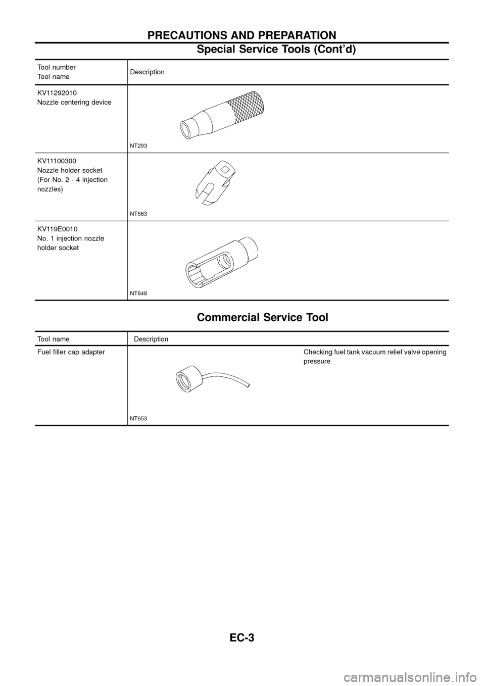
Tool number
Tool nameDescription
KV11292010
Nozzle centering device
NT293
KV11100300
Nozzle holder socket
(For No.2-4injection
nozzles)
NT563
KV119E0010
No. 1 injection nozzle
holder socket
NT648
Commercial Service Tool
Tool name Description
Fuel ®ller cap adapter
NT653
Checking fuel tank vacuum relief valve opening
pressure
PRECAUTIONS AND PREPARATION
Special Service Tools (Cont'd)
EC-3
Page 6 of 192
Supplemental Restraint System (SRS) ``AIR
BAG'' and ``SEAT BELT PRE-TENSIONER''
The Supplemental Restraint System such as ``AIR BAG'' and ``SEAT BELT PRE-TENSIONER'' used along with
a seat belt, helps to reduce the risk or severity of injury to the driver and front passenger in a frontal collision.
The SRS system composition which is available to NISSAN MODEL Y61 is as follows (The composition var-
ies according to the destination.):
Driver air bag module (located in the center of the steering wheel), front passenger air bag module (located
on the instrument panel on passenger side), seat belt pre-tensioner, a diagnosis sensor unit, warning lamp,
wiring harness and spiral cable.
Information necessary to service the system safely is included in theRS sectionof this Service Manual.
WARNING:
+To avoid rendering the SRS inoperative, which could increase the risk of personal injury or death
in the event of a collision which would result in air bag in¯ation, all maintenance must be performed
by an authorized NISSAN dealer.
+Improper maintenance, including incorrect removal and installation of the SRS, can lead to per-
sonal injury caused by unintentional activation of the system. For removal of Spiral Cable and Air
Bag Module, see the RS section.
+Do not use electrical test equipment on any circuit related to the SRS unless instructed to in this
Service Manual. Spiral cable and wiring harnesses covered with yellow insulation either just before
the harness connectors or for the complete harness are related to the SRS.
PRECAUTIONS AND PREPARATION
EC-4
Page 7 of 192
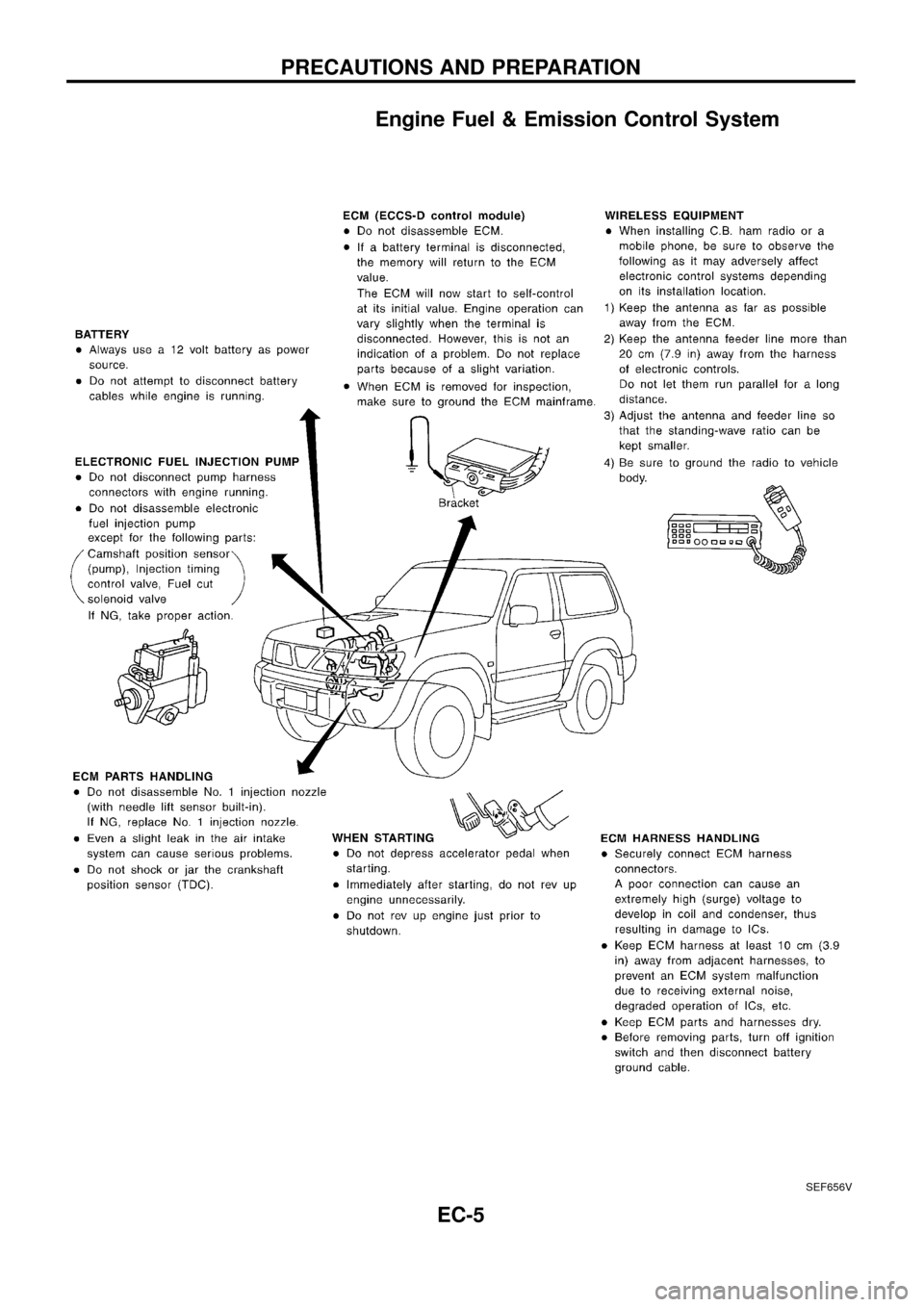
Engine Fuel & Emission Control System
SEF656V
PRECAUTIONS AND PREPARATION
EC-5
Page 8 of 192
Precautions
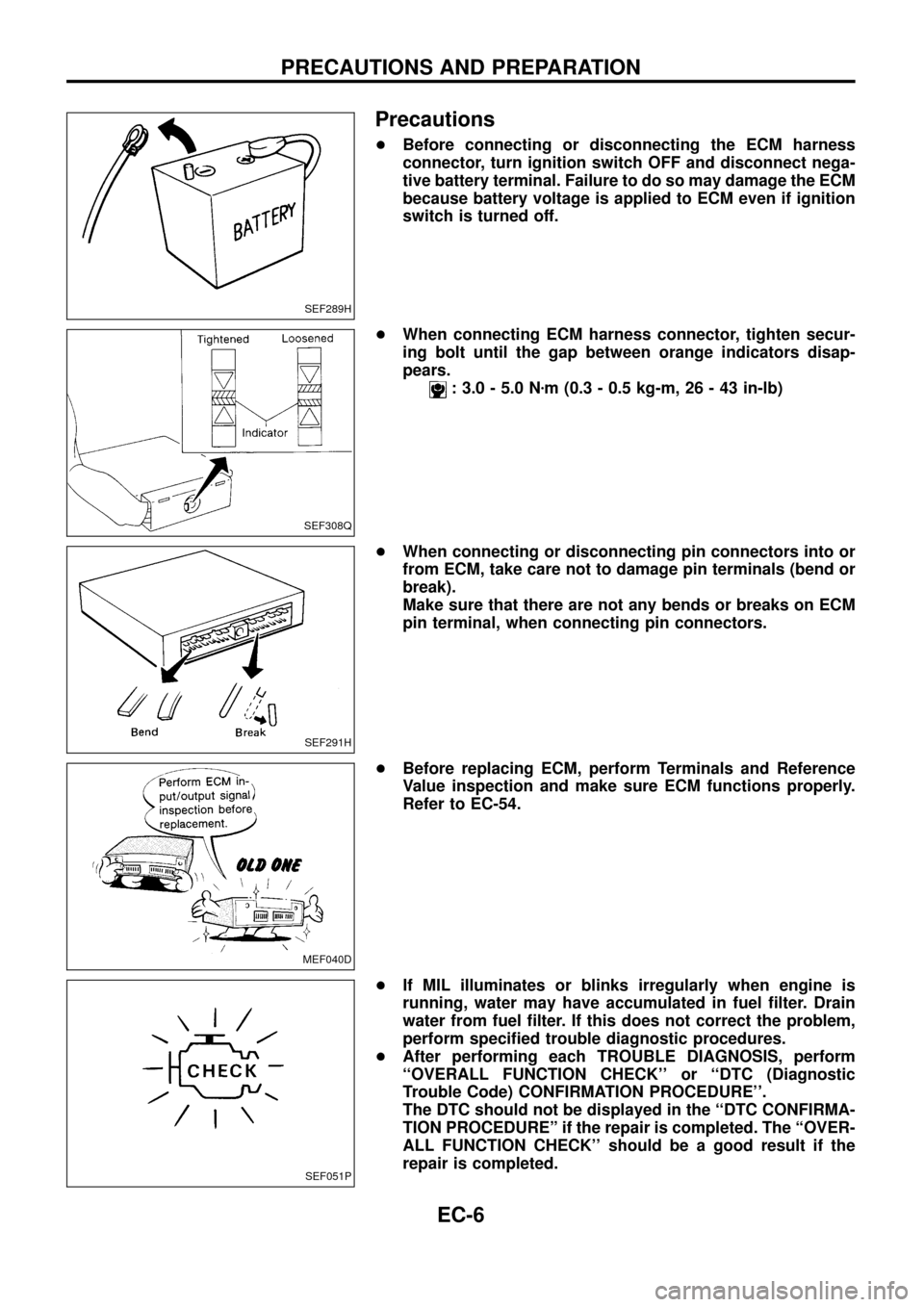
+Before connecting or disconnecting the ECM harness
connector, turn ignition switch OFF and disconnect nega-
tive battery terminal. Failure to do so may damage the ECM
because battery voltage is applied to ECM even if ignition
switch is turned off.
+When connecting ECM harness connector, tighten secur-
ing bolt until the gap between orange indicators disap-
pears.
: 3.0 - 5.0 Nzm (0.3 - 0.5 kg-m, 26 - 43 in-lb)
+When connecting or disconnecting pin connectors into or
from ECM, take care not to damage pin terminals (bend or
break).
Make sure that there are not any bends or breaks on ECM
pin terminal, when connecting pin connectors.
+Before replacing ECM, perform Terminals and Reference
Value inspection and make sure ECM functions properly.
Refer to EC-54.
+If MIL illuminates or blinks irregularly when engine is
running, water may have accumulated in fuel ®lter. Drain
water from fuel ®lter. If this does not correct the problem,
perform speci®ed trouble diagnostic procedures.
+After performing each TROUBLE DIAGNOSIS, perform
``OVERALL FUNCTION CHECK'' or ``DTC (Diagnostic
Trouble Code) CONFIRMATION PROCEDURE''.
The DTC should not be displayed in the ``DTC CONFIRMA-
TION PROCEDUREº if the repair is completed. The ``OVER-
ALL FUNCTION CHECK'' should be a good result if the
repair is completed.
SEF289H
SEF308Q
SEF291H
MEF040D
SEF051P
PRECAUTIONS AND PREPARATION
EC-6
Page 9 of 192
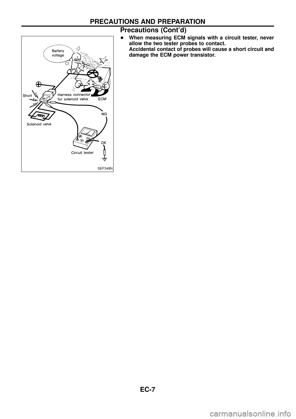
+When measuring ECM signals with a circuit tester, never
allow the two tester probes to contact.
Accidental contact of probes will cause a short circuit and
damage the ECM power transistor.
SEF348N
PRECAUTIONS AND PREPARATION
Precautions (Cont'd)
EC-7
Page 10 of 192
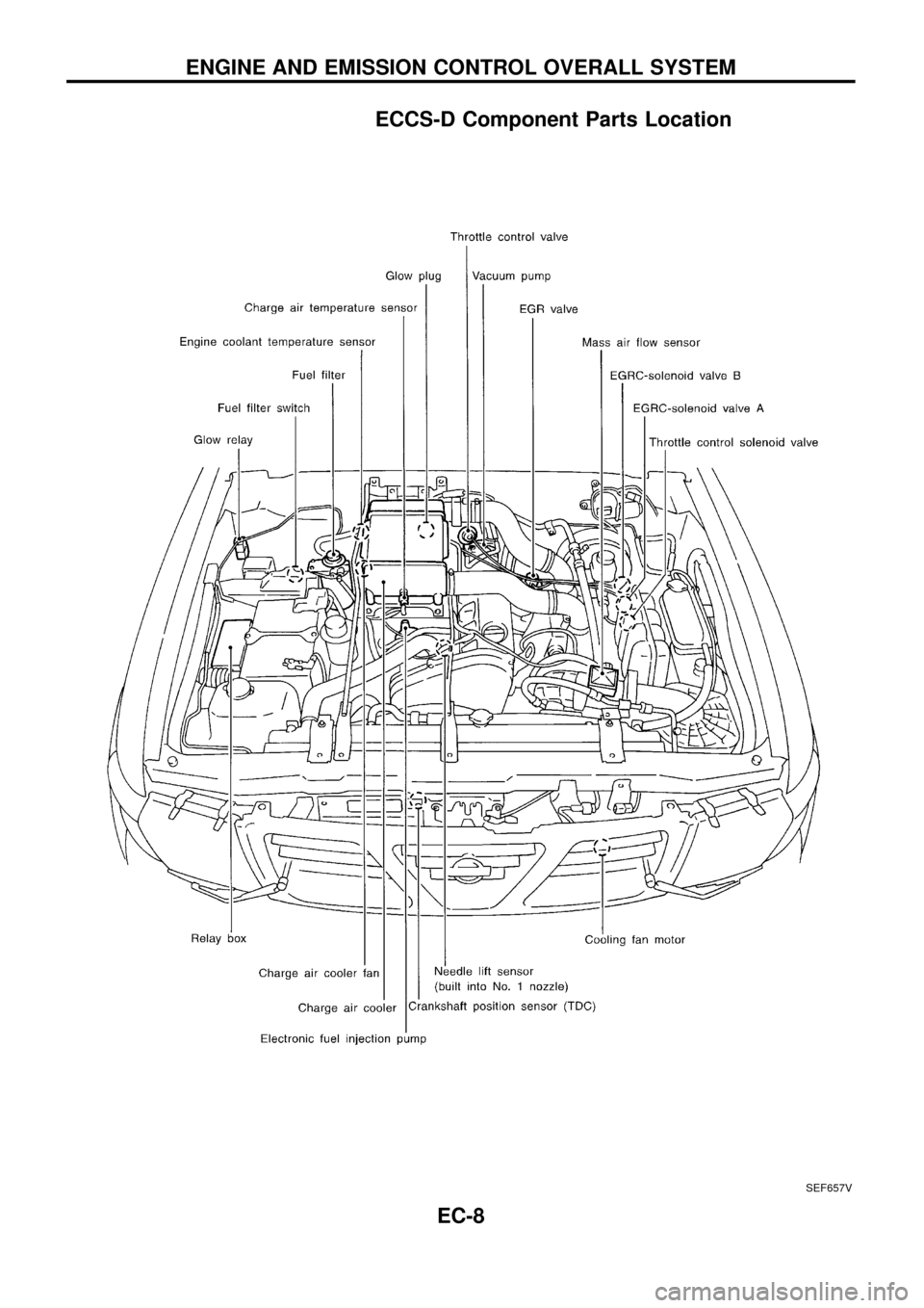
ECCS-D Component Parts Location
SEF657V
ENGINE AND EMISSION CONTROL OVERALL SYSTEM
EC-8