NISSAN PATROL 1998 Y61 / 5.G General Information Owner's Guide
Manufacturer: NISSAN, Model Year: 1998, Model line: PATROL, Model: NISSAN PATROL 1998 Y61 / 5.GPages: 47, PDF Size: 1.07 MB
Page 31 of 47

NOTICE:
The ¯ow chart indicates work procedures required to diagnose
problems effectively. Observe the following instructions before
diagnosing.
1) Use the ¯ow chart after locating probable causes of a prob-
lem following the ``Preliminary Check'', the ``Symptom
Chart'' or the ``Work Flow''.
2) After repairs, re-check that the problem has been com-
pletely eliminated.
3) Refer to Component Parts and Harness Connector Loca-
tion for the Systems described in each section for
identi®cation/location of components and harness con-
nectors.
4) Refer to the Circuit Diagram for Quick Pinpoint Check.
If you must check circuit continuity between harness con-
nectors in more detail, such as when a sub-harness is
used, refer to Wiring Diagram in each individual section
and Harness Layout in EL section for identi®cation of har-
ness connectors.
5) When checking circuit continuity, ignition switch should
be ``OFF''.
6) Before checking voltage at connectors, check battery volt-
age.
7) After accomplishing the Diagnostic Procedures and Elec-
trical Components Inspection, make sure that all harness
connectors are reconnected as they were.
Example
AGI056
HOW TO FOLLOW FLOW CHART IN TROUBLE DIAGNOSES
GI-30
Page 32 of 47

How to Follow This Flow Chart
Work and diagnostic procedure
Start to diagnose a problem using procedures indicated in
enclosed blocks, as shown in the following example.
CHECK POWER SUPPLY.
1) Turn ignition switch ``ON''.
2) Check voltage between terminal
V1and ground.
Battery voltage should exist.
bCheck item being performed.
Procedure, steps or
measurement results
Measurement results
Required results are indicated in bold type in the correspond-
ing block, as shown below:
These have the following meanings:
Battery voltage®11 - 14V or approximately 12V
Voltage: Approximately 0V®Less than 1V
Cross reference of work symbols in the text and
illustrations
Illustrations are provided as visual aids for work procedures.
For example, symbol
indicated in the left upper portion of
each illustration corresponds with the symbol in the ¯ow chart
for easy identi®cation. More precisely, the procedure under the
``CHECK POWER SUPPLY'' outlined previously is indicated by
illustration
.
Symbols used in illustrations
Symbols included in illustrations refer to measurements or pro-
cedures. Before diagnosing a problem, familiarize yourself with
each symbol.
DIRECTION MARK
Refer to ``CONNECTOR SYMBOLS'' on GI-12.
HOW TO FOLLOW FLOW CHART IN TROUBLE DIAGNOSES
GI-31
Page 33 of 47

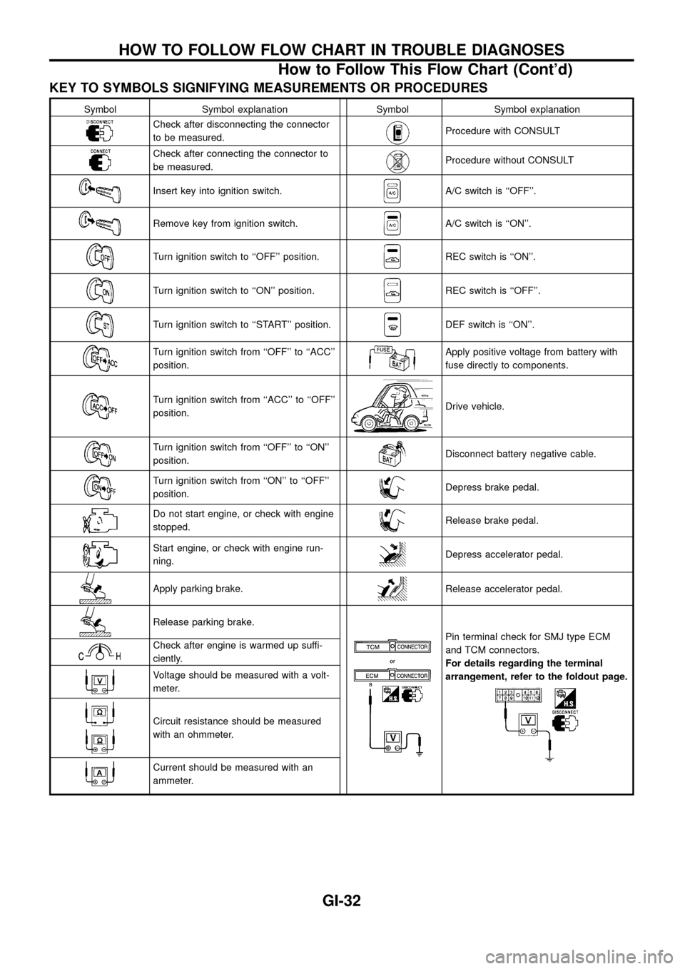
KEY TO SYMBOLS SIGNIFYING MEASUREMENTS OR PROCEDURES
Symbol Symbol explanation Symbol Symbol explanation
Check after disconnecting the connector
to be measured.Procedure with CONSULT
Check after connecting the connector to
be measured.Procedure without CONSULT
Insert key into ignition switch.A/C switch is ``OFF''.
Remove key from ignition switch.A/C switch is ``ON''.
Turn ignition switch to ``OFF'' position.REC switch is ``ON''.
Turn ignition switch to ``ON'' position.REC switch is ``OFF''.
Turn ignition switch to ``START'' position.DEF switch is ``ON''.
Turn ignition switch from ``OFF'' to ``ACC''
position.Apply positive voltage from battery with
fuse directly to components.
Turn ignition switch from ``ACC'' to ``OFF''
position.Drive vehicle.
Turn ignition switch from ``OFF'' to ``ON''
position.Disconnect battery negative cable.
Turn ignition switch from ``ON'' to ``OFF''
position.Depress brake pedal.
Do not start engine, or check with engine
stopped.Release brake pedal.
Start engine, or check with engine run-
ning.Depress accelerator pedal.
Apply parking brake.Release accelerator pedal.
Release parking brake.
Pin terminal check for SMJ type ECM
and TCM connectors.
For details regarding the terminal
arrangement, refer to the foldout page.Check after engine is warmed up suffi-
ciently.
Voltage should be measured with a volt-
meter.
Circuit resistance should be measured
with an ohmmeter.
Current should be measured with an
ammeter.
HOW TO FOLLOW FLOW CHART IN TROUBLE DIAGNOSES
How to Follow This Flow Chart (Cont'd)
GI-32
Page 34 of 47

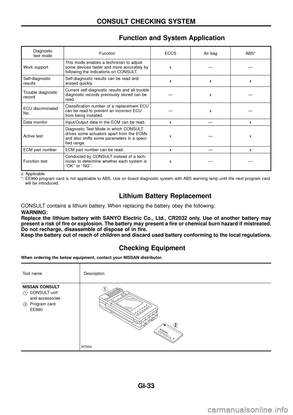
Function and System Application
Diagnostic
test modeFunction ECCS Air bag ABS*
Work supportThis mode enables a technician to adjust
some devices faster and more accurately by
following the indications on CONSULT.xÐÐ
Self-diagnostic
resultsSelf-diagnostic results can be read and
erased quickly.xxx
Trouble diagnostic
recordCurrent self-diagnostic results and all trouble
diagnostic records previously stored can be
read.ÐxÐ
ECU discriminated
No.Classi®cation number of a replacement ECU
can be read to prevent an incorrect ECU
from being installed.ÐxÐ
Data monitor Input/Output data in the ECM can be read. x Ð x
Active testDiagnostic Test Mode in which CONSULT
drives some actuators apart from the ECMs
and also shifts some parameters in a speci-
®ed range.xÐx
ECM part number ECM part number can be read. x Ð x
Function testConducted by CONSULT instead of a tech-
nician to determine whether each system is
``OK'' or ``NG''.xÐÐ
x: Applicable
*: EE960 program card is not applicable to ABS. Use on board diagnostic system with ABS warning lamp until the next program card
will be introduced.
Lithium Battery Replacement
CONSULT contains a lithium battery. When replacing the battery obey the following:
WARNING:
Replace the lithium battery with SANYO Electric Co., Ltd., CR2032 only. Use of another battery may
present a risk of ®re or explosion. The battery may present a ®re or chemical burn hazard if mistreated.
Do not recharge, disassemble of dispose of in ®re.
Keep the battery out of reach of children and discard used battery conforming to the local regulations.
Checking Equipment
When ordering the below equipment, contact your NISSAN distributor.
Tool name Description
NISSAN CONSULT
V1CONSULT unit
and accessories
V2Program card
EE960
NT004
CONSULT CHECKING SYSTEM
GI-33
Page 35 of 47

Loading Procedure
CONSULT Data Link Connector (DLC) Circuit
INSPECTION PROCEDURE
If the CONSULT cannot diagnose the system properly, check the following items.
Symptom Check item
CONSULT cannot access
any system.+CONSULT DLC power supply circuit (Terminal 7) and ground circuit (Terminal 8)
(For detailed circuit, refer to ``MIL & Data Link Connectors Wiring Diagram'' in EC section.)
+CONSULT DDL cable
CONSULT cannot access
individual system. (Other sys-
tems can be accessed.)+CONSULT program card (Check the appropriate CONSULT program card for the system. Refer
to GI-33.)
+Power supply and ground circuit for the control unit of the system
(For detailed circuit, refer to wiring diagram for each system.)
+Open or short circuit between the system and CONSULT DLC
(For detailed circuit, refer to wiring diagram for each system.)
SGI983
SGI984
CONSULT CHECKING SYSTEM
GI-34
Page 36 of 47

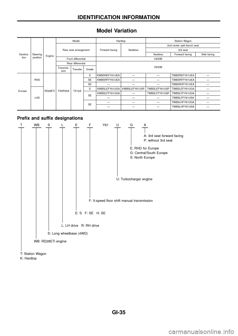
Model Variation
Destina-
tionSteering
positionEngineModel Hardtop Station Wagon
Rear seat arrangement Forward facing Seatless2nd center split bench seat
3rd seat
Seatless Forward facing Side facing
Front differential H233B
Rear differential
H233B
Transmis-
sionTransfer Grade
EuropeRHD
RD28ETi FS5R30A TX12AS KWBSREFY61UEA Ð Ð TWBSREFY61UEA Ð
SE KWBSRFFY61UEA Ð Ð TWBSRFFY61UEA Ð
SE Ð Ð Ð TWBSRHFY61UEA Ð
LHDS KWBSLEFY61UGA KWBSLEFY61USP TWBSLEFY61USP TWBSLEFY61UGA Ð
SEKWBSLFFY61UGA Ð TWBSLFFY61USP TWBSLFFY61UGA Ð
Ð Ð Ð TWBSLFFY61USA Ð
SEÐ Ð Ð TWBSLHFY61UGA Ð
Ð Ð Ð TWBSLHFY61USA Ð
Pre®x and suffix designations
TWBSLEFY61 UGA
A: 3rd seat forward facing
P: without 3rd seat
E: RHD for Europe
G: Central/South Europe
S: North Europe
U: Turbocharger engine
F: 5-speed ¯oor shift manual transmission
E:SF:SEH:SE
L: LH drive R: RH drive
S: Long wheelbase (4WD)
WB: RD28ETi engine
T: Station Wagon
K: Hardtop
IDENTIFICATION INFORMATION
GI-35
Page 37 of 47

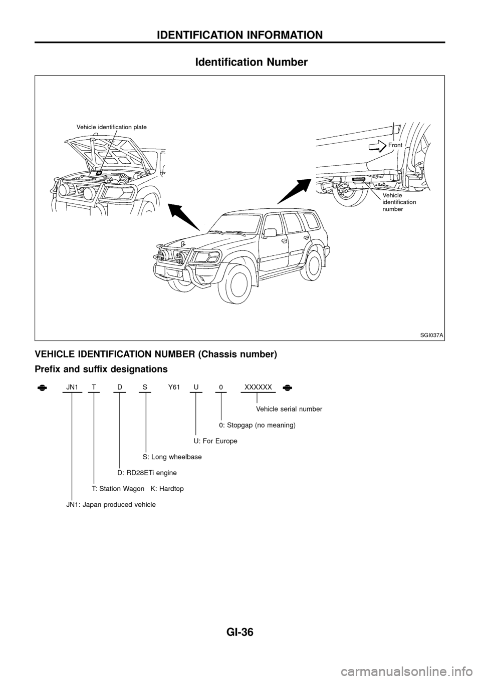
Identi®cation Number
VEHICLE IDENTIFICATION NUMBER (Chassis number)
Pre®x and suffix designations
JN1TDSY61 U0XXXXXX
Vehicle serial number
0: Stopgap (no meaning)
U: For Europe
S: Long wheelbase
D: RD28ETi engine
T: Station Wagon K: Hardtop
JN1: Japan produced vehicle
SGI037A
Vehicle identi®cation plate
Vehicle
identi®cation
numberFront
IDENTIFICATION INFORMATION
GI-36
Page 38 of 47

IDENTIFICATION PLATE
ENGINE SERIAL NUMBER
MANUAL TRANSMISSION SERIAL NUMBER
TRANSFER SERIAL NUMBER
SGI851
SGI028A
SGI018A
SGI020A
IDENTIFICATION INFORMATION
Identi®cation Number (Cont'd)
GI-37
Page 39 of 47

Dimensions
Wagon Hardtop
Overall length mm (in) 4,965 (195.5)
5,010 (197.2)*4,395 (173.0)
4,440 (174.8)*
Overall width mm (in) 1,840 (72.4)
1,930 (76.0)*1,840 (72.4)
1,930 (76.0)*
Overall height mm (in) 1,855 (73.0) 1,840 (72.4)
Front tread mm (in) 1,555 (61.2)
1,605 (63.2)*1,555 (61.2)
1,605 (63.2)*
Rear tread mm (in) 1,575 (62.0)
1,625 (64.0)*1,575 (62.0)
1,625 (64.0)*
Wheelbase mm (in) 2,970 (116.9) 2,400 (94.5)
*: For models equipped with 265/70R16 tires
Wheels & Tires
Road wheel
Size 6JJ-16*1 8JJ-16*1
Offset mm (in) 35 (1.38) 10 (0.39)
Tire size 235/80R16 109S 265/70R16 112S
*1: Steel wheel and Aluminum wheel
IDENTIFICATION INFORMATION
GI-38
Page 40 of 47

WARNING:
+Never get under the vehicle while it is supported only by the jack. Always use safety stands to
support the frame when you have to get under the vehicle.
+Place wheel chocks at both front and back of the wheel which is diagonally opposite the jack
position.
Example: If the jack is positioned at the LH front wheel, place wheel chocks at RH rear wheel.
Screw Jack
Garage Jack and Safety Stand
CAUTION:
+Place a wooden or rubber block between safety stand and vehicle body when the supporting body
is ¯at.
SGI016A
SGI021A
LIFTING POINTS AND TOW TRUCK TOWING
GI-39