cooling NISSAN PATROL 2000 Electronic Owner's Manual
[x] Cancel search | Manufacturer: NISSAN, Model Year: 2000, Model line: PATROL, Model: NISSAN PATROL 2000Pages: 1033, PDF Size: 30.71 MB
Page 737 of 1033

Wiring Diagram Codes (Cell Codes)
Use the chart below to find out what each wiring diagram code
stands for.
Refer to the wiring diagram code in the alphabetical index to find
the location (Page number) of each wiring diagram.
Code Section Wiring Diagram Name
A/C,A HA Auto Air Conditioner
A/C,M HA Manual Air Conditioner
A/CCUT EC Air Conditioner Control
A/T AT A/T
ABS BR Anti-lock Brake System
ACC/SW EC Accelerator Switch (FC)
ACL/SW EC Accelerator Position Switch
APS EC Accelerator Position Sensor
ASCD EL Automatic Speed Control Device
AT/C EC A/T Control
BACK/L EL Back-up Lamp
BCDD EC BCDD System
BOOST EC Turbo Charger Boost Sensor
BRK/SW EC Brake Switch Signal
CHARGE EL Charging System
CHIME EL Warning Chime
CHOKE EC Automatic Choke
CKPS EC Crankshaft Position Sensor (OBD)
COOL/B HA Cool Box
COOL/F EC Cooling Fan Control
CORNER EL Cornering Lamp
DEF EL Rear Window Defogger
DIFF/L PD Differential Lock Control System
DTRL ELHeadlamp Ð With Daytime Light
System
ECMRLY EC ECM Relay
ECTS EC Engine Coolant Temperature Sensor
EGVC/V EC EGR Volume Control Valve
EXH ECExhaust Gas Control Valve Control
Solenoid Valve
F/FOG EL Front Fog Lamp
F/PUMP EC Fuel Pump
FCUT EC Fuel Cut System
FICD EC IACV-FICD Solenoid Valve
FIPOT EC ISC-FI POT
FPCM EC Fuel Pump Control Module
GLOW EC Quick Glow System
HEATER HA Heater System
HEATUP EC Heat up SwitchCode Section Wiring Diagram Name
HLC EL Headlamp Wiper and Washer
HORN EL Horn
IGN EC Ignition Control System
ILL EL Illumination
INJPMP ECElectronic Control Fuel Injection
Pump
INT/V ECIntake Air Control Valve Control
Solenoid Valve
MAFS EC Mass Air Flow Sensor
MAIN ECMain Power Supply and Ground Cir-
cuit
METER ELSpeedometer, Tachometer, Temp.,
Oil and Fuel Gauges
MIL/DL EC Mil and Data Link Connectors
MULTI EL Multi-remote Control System
NATS EL Nissan Anti-Theft System
P/ANT EL Power Antenna
PNP/SW EC Park/Neutral Position Switch
POWER EL Power Supply Routing
R/COOL HA Rear Cooler System
R/FOG EL Rear Fog Lamp
R/HEAT HA Rear Heater System
REMOTE EL Audio (Remote Control Switch)
ROOM/L EL Interior Room Lamp
S/LOCK EL Power Door Lock Ð Super Lock
S/SIG EC Start Signal
S/TANK FE Sub Fuel Tank Control System
SHIFT AT A/T Shift Lock System
SRS RS Supplemental Restraint System
STAB RA Stabilizer Release Device
START EL Starting System
STOP/L EL Stop Lamp
SWL/V ECSwirl Control Valve Control Solenoid
Valve
TAIL/L EL Parking, License and Tail Lamps
TURN ELTurn Signal and Hazard Warning
Lamps
VSS EC Vehicle Speed Sensor
WARN EL Warning Lamps
WIRING DIAGRAM CODES (CELL CODES)
EL-1227
Page 747 of 1033
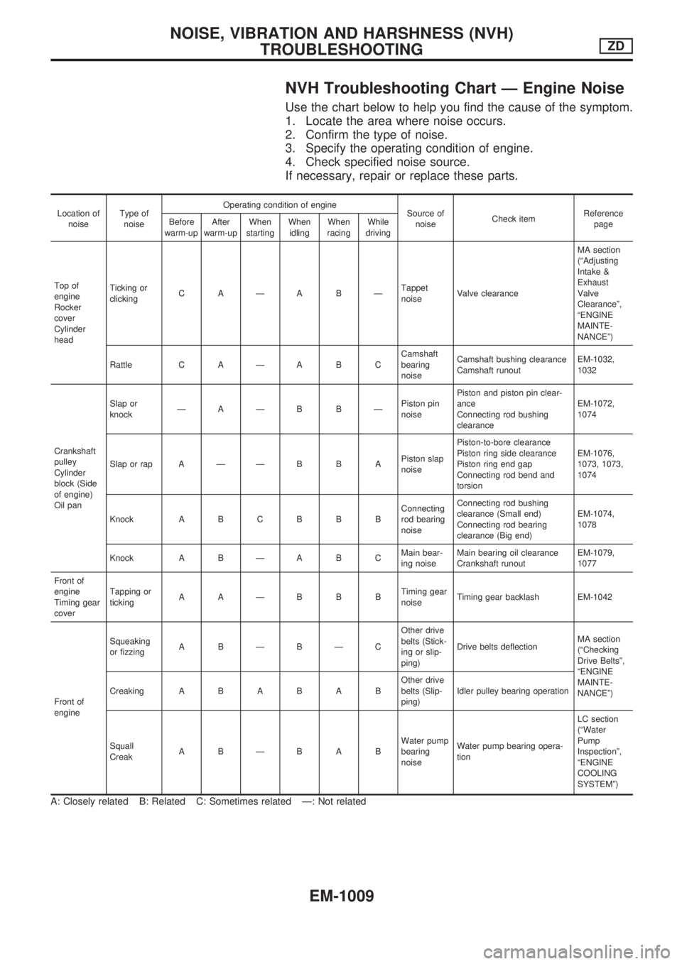
NVH Troubleshooting Chart Ð Engine Noise
Use the chart below to help you find the cause of the symptom.
1. Locate the area where noise occurs.
2. Confirm the type of noise.
3. Specify the operating condition of engine.
4. Check specified noise source.
If necessary, repair or replace these parts.
Location of
noiseType of
noiseOperating condition of engine
Source of
noiseCheck itemReference
page Before
warm-upAfter
warm-upWhen
startingWhen
idlingWhen
racingWhile
driving
Top of
engine
Rocker
cover
Cylinder
headTicking or
clickingCAÐABÐTappet
noiseValve clearanceMA section
(ªAdjusting
Intake &
Exhaust
Valve
Clearanceº,
ªENGINE
MAINTE-
NANCEº)
Rattle C A Ð A B CCamshaft
bearing
noiseCamshaft bushing clearance
Camshaft runoutEM-1032,
1032
Crankshaft
pulley
Cylinder
block (Side
of engine)
Oil panSlap or
knockÐAÐB BÐPiston pin
noisePiston and piston pin clear-
ance
Connecting rod bushing
clearanceEM-1072,
1074
Slap or rap A Ð Ð B B APiston slap
noisePiston-to-bore clearance
Piston ring side clearance
Piston ring end gap
Connecting rod bend and
torsionEM-1076,
1073, 1073,
1074
Knock A B C B B BConnecting
rod bearing
noiseConnecting rod bushing
clearance (Small end)
Connecting rod bearing
clearance (Big end)EM-1074,
1078
Knock A B Ð A B CMain bear-
ing noiseMain bearing oil clearance
Crankshaft runoutEM-1079,
1077
Front of
engine
Timing gear
coverTapping or
tickingAAÐBBBTiming gear
noiseTiming gear backlash EM-1042
Front of
engineSqueaking
or fizzingABÐBÐCOther drive
belts (Stick-
ing or slip-
ping)Drive belts deflectionMA section
(ªChecking
Drive Beltsº,
ªENGINE
MAINTE-
NANCEº) CreakingABABABOther drive
belts (Slip-
ping)Idler pulley bearing operation
Squall
CreakABÐBABWater pump
bearing
noiseWater pump bearing opera-
tionLC section
(ªWater
Pump
Inspectionº,
ªENGINE
COOLING
SYSTEMº)
A: Closely related B: Related C: Sometimes related Ð: Not related
NOISE, VIBRATION AND HARSHNESS (NVH)
TROUBLESHOOTINGZD
EM-1009
Page 763 of 1033
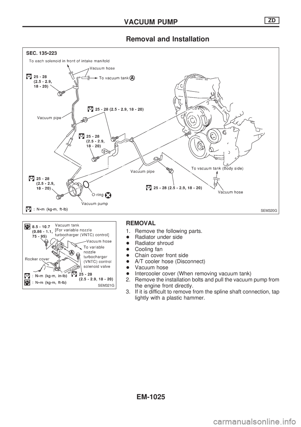
Removal and Installation
REMOVAL
1. Remove the following parts.
+Radiator under side
+Radiator shroud
+Cooling fan
+Chain cover front side
+A/T cooler hose (Disconnect)
+Vacuum hose
+Intercooler cover (When removing vacuum tank)
2. Remove the installation bolts and pull the vacuum pump from
the engine front directly.
3. If it is difficult to remove from the spline shaft connection, tap
lightly with a plastic hammer.
SEM320G
SEM321G
VACUUM PUMPZD
EM-1025
Page 765 of 1033
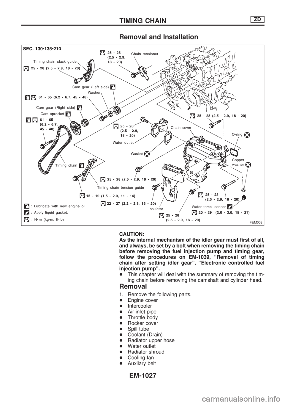
Removal and Installation
CAUTION:
As the internal mechanism of the idler gear must first of all,
and always, be set by a bolt when removing the timing chain
before removing the fuel injection pump and timing gear,
follow the procedures on EM-1039, ªRemoval of timing
chain after setting idler gearº, ªElectronic controlled fuel
injection pumpº.
+This chapter will deal with the summary of removing the tim-
ing chain before removing the camshaft and cylinder head.
Removal
1. Remove the following parts.
+Engine cover
+Intercooler
+Air inlet pipe
+Throttle body
+Rocker cover
+Spill tube
+Coolant (Drain)
+Radiator upper hose
+Water outlet
+Radiator shroud
+Cooling fan
+Auxilary belt
FEM003
TIMING CHAINZD
EM-1027
Page 778 of 1033
Removal
1. Remove the following parts.
+Undercover
+Engine oil (Drain)
+Engine coolant (Drain)
+Engine cover
+Intercooler
+Air inlet pipe
+Air cleaner case
+Throttle body
+Swirl and intake air control valve control solenoid valve and
bracket
+Vacuum tank
+Glow plate
+Rocker cover
+Spill tube
+Radiator shrouds (Rear and Lower)
+Cooling fan
+Radiator hose (Upper and Lower)
+Auxiliary belt and auto tensioner.
2. Remove the alternator.
3. Remove the A/C compressor and bracket with piping con-
nected. Move and support it at the LH side of engine bay with
a rope to avoid putting load on piping.
Refer to HA section in Nissan Service Manual (Supplement
I: Publication No. SM0E-Y61AE0E.)
4. Remove the chain cover, timing chain and other parts in
connection.
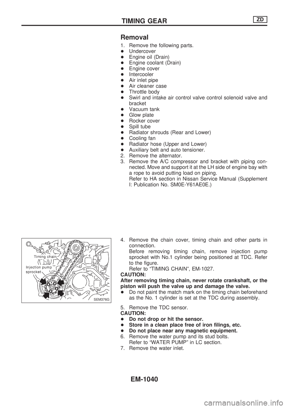
Before removing timing chain, remove injection pump
sprocket with No.1 cylinder being positioned at TDC. Refer
to the figure.
Refer to ªTIMING CHAINº, EM-1027.
CAUTION:
After removing timing chain, never rotate crankshaft, or the
piston will push the valve up and damage the valve.
+Do not paint the match mark on the timing chain beforehand
as the No. 1 cylinder is set at the TDC during assembly.
5. Remove the TDC sensor.
CAUTION:
+Do not drop or hit the sensor.
+Store in a clean place free of iron filings, etc.
+Do not place near any magnetic equipment.
6. Remove the water pump and its stud bolts.
Refer to ªWATER PUMPº in LC section.
7. Remove the water inlet.
SEM376G
TIMING GEARZD
EM-1040
Page 799 of 1033
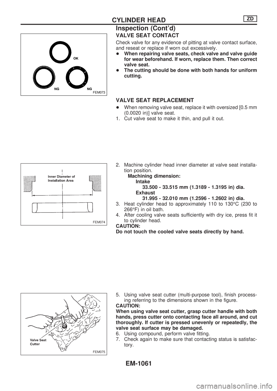
VALVE SEAT CONTACT
Check valve for any evidence of pitting at valve contact surface,
and reseat or replace if worn out excessively.
+When repairing valve seats, check valve and valve guide
for wear beforehand. If worn, replace them. Then correct
valve seat.
+The cutting should be done with both hands for uniform
cutting.
VALVE SEAT REPLACEMENT
+When removing valve seat, replace it with oversized [0.5 mm
(0.0020 in)] valve seat.
1. Cut valve seat to make it thin, and pull it out.
2. Machine cylinder head inner diameter at valve seat installa-
tion position.
Machining dimension:
Intake
33.500 - 33.515 mm (1.3189 - 1.3195 in) dia.
Exhaust
31.995 - 32.010 mm (1.2596 - 1.2602 in) dia.
3. Heat cylinder head to approximately 110 to 130ÉC (230 to
266ÉF) in oil bath.
4. After cooling valve seats sufficiently with dry ice, press fit it
to cylinder head.
CAUTION:
Do not touch the cooled valve seats directly by hand.
5. Using valve seat cutter (multi-purpose tool), finish process-
ing referring to the dimensions shown in the figure.
CAUTION:
When using valve seat cutter, grasp cutter handle with both
hands, press cutter onto contacting face all around, and cut
thoroughly. If cutter is pressed unevenly or repeatedly, the
valve seat surface may be damaged.
6. Using compound, perform valve fitting.
7. Check again to make sure that contacting status is satisfac-
tory.
FEM073
FEM074
FEM075
CYLINDER HEADZD
Inspection (Cont'd)
EM-1061
Page 802 of 1033
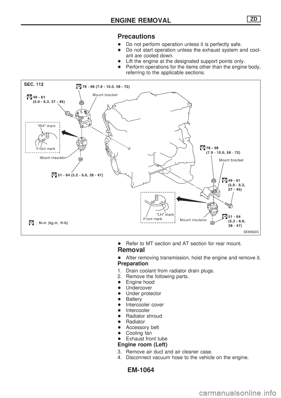
Precautions
+Do not perform operation unless it is perfectly safe.
+Do not start operation unless the exhaust system and cool-
ant are cooled down.
+Lift the engine at the designated support points only.
+Perform operations for the items other than the engine body,
referring to the applicable sections.
+Refer to MT section and AT section for rear mount.
Removal
+After removing transmission, hoist the engine and remove it.
Preparation
1. Drain coolant from radiator drain plugs.
2. Remove the following parts.
+Engine hood
+Undercover
+Under protector
+Battery
+Intercooler cover
+Intercooler
+Radiator shroud
+Radiator
+Accessory belt
+Cooling fan
+Exhaust front tube
Engine room (Left)
3. Remove air duct and air cleaner case.
4. Disconnect vacuum hose to the vehicle on the engine.
SEM362G
ENGINE REMOVALZD
EM-1064
Page 857 of 1033
Supplemental Restraint System (SRS) ªAIR
BAGº and ªSEAT BELT PRE-TENSIONERº
The Supplemental Restraint System such as ªAIR BAGº and ªSEAT BELT PRE-TENSIONERº used along
with a seat belt, helps to reduce the risk or severity of injury to the driver and front passenger for certain
types of collision. The SRS system composition which is available to NISSAN MODEL Y61 is as follows (The
composition varies according to the destination and optional equipment.):
+For a frontal collision
The Supplemental Restraint System consists of driver air bag module (located in the center of the
steering wheel), front passenger air bag module (located on the instrument panel on passenger side),
seat belt pre-tensioners, a diagnosis sensor unit, warning lamp, wiring harness and spiral cable.
+For a side collision
The Supplemental Restraint System consists of front side air bag module (located in the outer side of
front seat), satellite sensor, diagnosis sensor unit (one of components of air bags for a frontal collision),
wiring harness, warning lamp (one of components of air bags for a frontal collision).
Information necessary to service the system safely is included in theRS sectionof this Service Manual.
WARNING:
+To avoid rendering the SRS inoperative, which could increase the risk of personal injury or death
in the event of a collision which would result in air bag inflation, all maintenance should be per-
formed by an authorized NISSAN dealer.
+Improper maintenance, including incorrect removal and installation of the SRS, can lead to per-
sonal injury caused by unintentional activation of the system. For removal of Spiral Cable and
Air Bag Module, see the RS section.
+Do not use electrical test equipment on any circuit related to the SRS unless instructed to in this
Service Manual. Spiral cable and wiring harnesses covered with yellow insulation tape either just
before the harness connectors or for the complete harness are related to the SRS.
Precautions for Refrigerant Connection
A new type refrigerant connection has been introduced to all refrigerant lines except the following location.
+Expansion valve to cooling unit
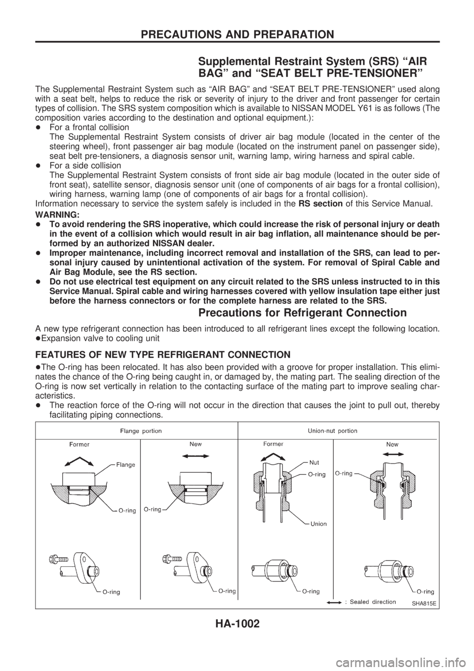
FEATURES OF NEW TYPE REFRIGERANT CONNECTION
+The O-ring has been relocated. It has also been provided with a groove for proper installation. This elimi-
nates the chance of the O-ring being caught in, or damaged by, the mating part. The sealing direction of the
O-ring is now set vertically in relation to the contacting surface of the mating part to improve sealing char-
acteristics.
+The reaction force of the O-ring will not occur in the direction that causes the joint to pull out, thereby
facilitating piping connections.
SHA815E
PRECAUTIONS AND PREPARATION
HA-1002
Page 880 of 1033
A
A/T - Wiring diagram ............................. AT-1009
A/T control ............................................. EC-1148
A/T fluid temperature sensor ................. AT-1081
A/T mode switch .................................... AT-1095
A/T self-diagnoses ................................. AT-1028
A/T shift lock system - Wiring
diagram .............................................. AT-1117
A/T shift lock system ............................. AT-1116
A/T trouble diagnoses ........................... AT-1036
APS - Wiring diagram ........................... EC-1125
ASCD (automatic speed control
device) ............................................... EL-1110
ASCD - Wiring diagram ......................... EL-1111
AT/C - Wiring diagram .......................... EC-1150
Accelerator control system .................... FE-1007
Accelerator position sensor .................. EC-1125
Air bag disposal .................................... RS-1015
Air bag precautions ................................ GI-1002
Air bag ................................................... RS-1003
Air cleaner filter replacement ............... MA-1019
Air conditioner cut control ..................... EC-1021
Air flow meter - See Mass air flow
sensor ................................................ EC-1086
Alternator ............................................... EL-1041
Angular tightening application .............. EM-1003
Anti-lock brake system - Wiring
diagram ............................................. BR-1002
Audio ...................................................... EL-1108
Automatic speed control system - See
ASCD ................................................. EL-1110
Automatic transmission fluid
replacement ...................................... MA-1021
B
BACK/L - Wiring diagram ...................... EL-1051
BOOST - Wiring diagram ...................... EC-1204
Back-up lamp ......................................... EL-1051
Basic inspection .................................... EC-1049
Battery ................................................... EL-1035
Boring/horning cylinder block ............... EM-1075
C
CHARGE - Wiring diagram ................... EL-1040
CKPS - Wiring diagram ........................ EC-1140
CONSULT for engine ............................ EC-1038
CONSULT general information .............. GI-1003
COOL/F - Wiring diagram ..................... EC-1105
CORNER - Wiring diagram ................... EL-1054
Camshaft inspection ............................. EM-1032
Charging system .................................... EL-1040
Chassis and body maintenance ........... MA-1020
Clutch operating cylinder ....................... CL-1003
Collision diagnosis ................................ RS-1052
Combination meter ................................ EL-1073Combination switch ............................... EL-1042
Compression pressure ......................... EM-1010
Compressor mounting ........................... HA-1023
Connecting rod bearing clearance ....... EM-1078
Connecting rod bushing clearance ....... EM-1074
Connecting rod ..................................... EM-1074
Control valve (A/T) ................................ AT-1148
Converter housing installation ............... AT-1128
Coolant mixture ratio ............................ MA-1010
Coolant replacement ............................ MA-1014
Cooling fan control ................................ EC-1105
Cornering lamp ...................................... EL-1054
Crankcase emission control system -
See Positive crankcase ventilation ... EC-1022
Crankcase ventilation system - See
Positive crankcase ventilation ........... EC-1022
Crankshaft position sensor (TDC) ........ EC-1140
Crankshaft ............................................ EM-1077
Cruise control - See ASCD ................... EL-1110
Cylinder block boring ............................ EM-1020
Cylinder block ....................................... EM-1067
Cylinder head bolt tightening ................ EM-1034
Cylinder head ....................................... EM-1053
D
DEF - Wiring diagram ............................ EL-1102
DTRL - Wiring diagram ......................... EL-1044
Data link connector for Consult ............ EC-1038
Daytime light system ............................. EL-1044
Diagnosis sensor unit ........................... RS-1008
Diagnostic trouble code (DTC) for
OBD system ...................................... EC-1032
Dome light - See Interior lamp .............. EL-1067
Door mirror ............................................ BT-1007
Door trim ................................................ BT-1004
Drive belt inspection ............................. MA-1011
Drive plate runout ................................. EM-1095
Dropping resistor (A/T) .......................... AT-1086
E
ECCS-D control module .. EC-1068, 1117, 1189,
1191, 1196, 1200
ECM input/output signal ........................ EC-1068
ECTS - Wiring diagram ......................... EC-1092
EGR - Wiring diagram .......................... EC-1209
EGR volume control valve .................... EC-1207
Electrical unit ......................................... EL-1231
Electrical units location .......................... EL-1185
Electronic fuel injection pump .... EC-1119, 1153,
1159, 1165, 1171, 1177, 1180, 1215
Engine control circuit diagram .............. EC-1015
Engine control component parts
location .............................................. EC-1011
Engine control system diagram and
chart .................................................. EC-1016
ALPHABETICAL INDEX
IDX-1002
Page 884 of 1033
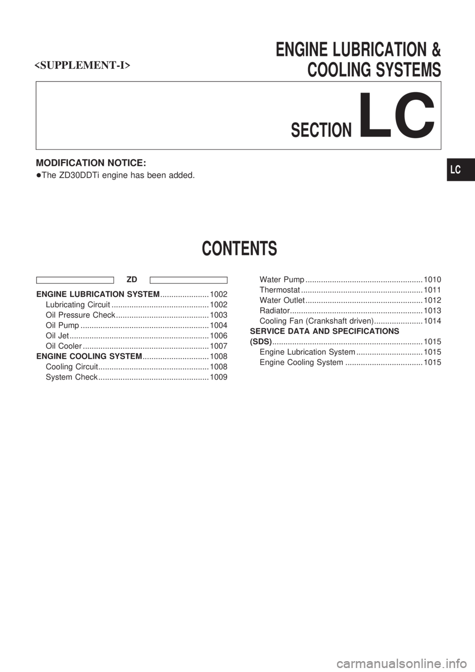
ENGINE LUBRICATION &
COOLING SYSTEMS
SECTION
LC
MODIFICATION NOTICE:
+The ZD30DDTi engine has been added.
CONTENTS
ZD
ENGINE LUBRICATION SYSTEM...................... 1002
Lubricating Circuit ............................................ 1002
Oil Pressure Check .......................................... 1003
Oil Pump .......................................................... 1004
Oil Jet ............................................................... 1006
Oil Cooler ......................................................... 1007
ENGINE COOLING SYSTEM.............................. 1008
Cooling Circuit.................................................. 1008
System Check .................................................. 1009Water Pump ..................................................... 1010
Thermostat ....................................................... 1011
Water Outlet ..................................................... 1012
Radiator............................................................ 1013
Cooling Fan (Crankshaft driven)...................... 1014
SERVICE DATA AND SPECIFICATIONS
(SDS).................................................................... 1015
Engine Lubrication System .............................. 1015
Engine Cooling System ................................... 1015
LC