NISSAN PATROL 2004 Electronic Owner's Guide
Manufacturer: NISSAN, Model Year: 2004, Model line: PATROL, Model: NISSAN PATROL 2004Pages: 579, PDF Size: 26.61 MB
Page 31 of 579

j21License lamp ®nisher
PIIB1973E
EXTERIOR
BT-4011
Page 32 of 579

Rear Seat
WAGON (Type-III)
PIIB1975E
SEAT
BT-4012
Page 33 of 579
CLUTCH
SECTION
CL
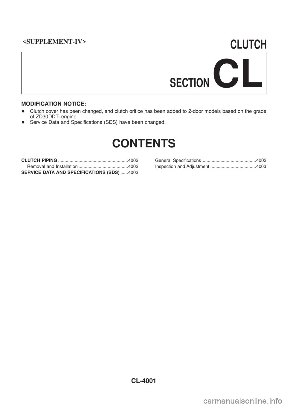
MODIFICATION NOTICE:
+ Clutch cover has been changed, and clutch ori®ce has been added to 2-door models based on the grade
of ZD30DDTi engine.
+ Service Data and Speci®cations (SDS) have been changed.
CONTENTS
CLUTCH PIPING .......................................................4002
Removal and Installation .......................................4002
SERVICE DATA AND SPECIFICATIONS (SDS) ......4003General Speci®cations ...........................................4003
Inspection and Adjustment ....................................4003
CL-4001
Page 34 of 579
Removal and Installation
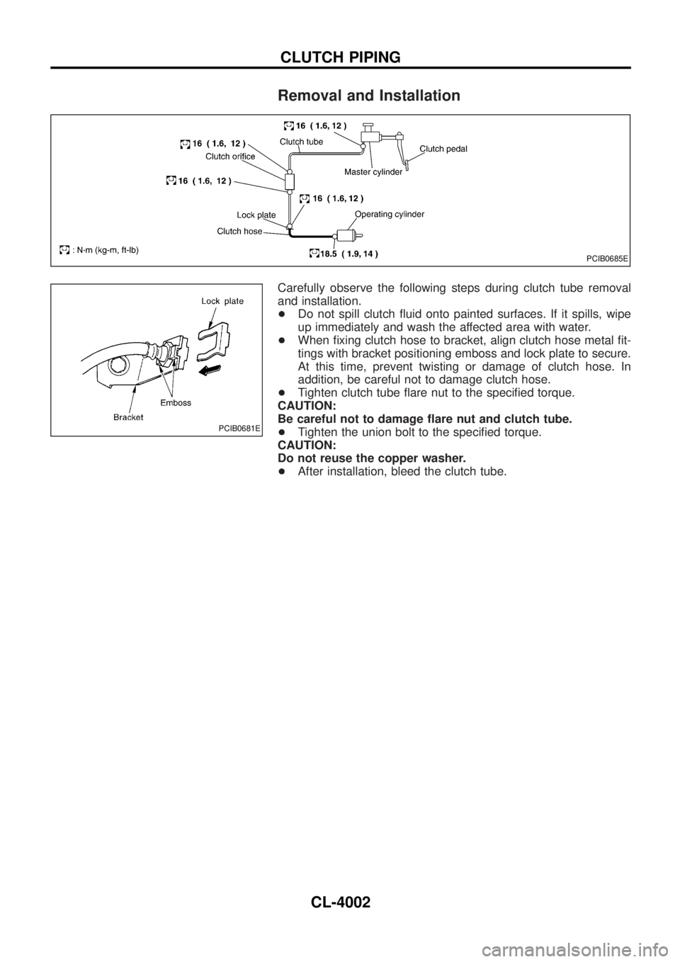
Carefully observe the following steps during clutch tube removal
and installation.
+Do not spill clutch ¯uid onto painted surfaces. If it spills, wipe
up immediately and wash the affected area with water.
+When ®xing clutch hose to bracket, align clutch hose metal ®t-
tings with bracket positioning emboss and lock plate to secure.
At this time, prevent twisting or damage of clutch hose. In
addition, be careful not to damage clutch hose.
+Tighten clutch tube ¯are nut to the speci®ed torque.
CAUTION:
Be careful not to damage ¯are nut and clutch tube.
+Tighten the union bolt to the speci®ed torque.
CAUTION:
Do not reuse the copper washer.
+After installation, bleed the clutch tube.
PCIB0685E
PCIB0681E
CLUTCH PIPING
CL-4002
Page 35 of 579
General Speci®cations
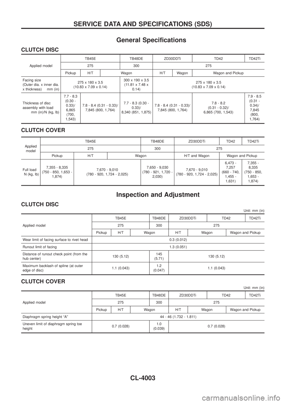
CLUTCH DISC
Applied modelTB45E TB48DE ZD30DDTi TD42 TD42Ti
275 300 275
Pickup H/T Wagon H/T Wagon Wagon and Pickup
Facing size
(Outer dia. x inner dia.
x thickness) mm (in)275 x 180 x 3.5
(10.83 x 7.09 x 0.14)300 x 190 x 3.5
(11.81 x 7.48 x
0.14)275 x 180 x 3.5
(10.83 x 7.09 x 0.14)
Thickness of disc
assembly with load
mm (in)/N (kg, lb)7.7 - 8.3
(0.30 -
0.33)/
6,865
(700,
1,543)7.8 - 8.4 (0.31 - 0.33)/
7,845 (800, 1,764)7.7 - 8.3 (0.30 -
0.33)/
8,340 (851, 1,875)7.8 - 8.4 (0.31 - 0.33)/
7,845 (800, 1,764)7.8 - 8.2
(0.31 - 0.32)/
6,865 (700, 1,543)7.9 - 8.5
(0.31 -
0.34)/
7,845
(800,
1,764)
CLUTCH COVER
Applied
modelTB45E TB48DE ZD30DDTi TD42 TD42Ti
275 300 275
Pickup H/T Wagon H/T and Wagon Wagon and Pickup
Full load
N (kg, lb)7,355 - 8,335
(750 - 850, 1,653 -
1,874)7,670 - 9,010
(780 - 920, 1,724 - 2,025)7,650 - 9,030
(780 - 921, 1,720 -
2,030)7,670 - 9,010
(780 - 920, 1,724 - 2,025)6,473 -
7,257
(660 - 740,
1,455 -
1,631)7,355 -
8,335
(750 - 850,
1,653 -
1,874)
Inspection and Adjustment
CLUTCH DISC
Unit: mm (in)
Applied modelTB45E TB48DE ZD30DDTi TD42 TD42Ti
275 300 275
Pickup H/T Wagon H/T Wagon Wagon and Pickup
Wear limit of facing surface to rivet head 0.3 (0.012)
Runout limit of facing 1.3 (0.051)
Distance of runout check point (from the
hub center)130 (5.12)145
(5.71)130 (5.12)
Maximum backlash of spline (at outer
edge of disc)1.1 (0.043)1.2
(0.047)1.1 (0.043)
CLUTCH COVER
Unit: mm (in)
Applied modelTB45E TB48DE ZD30DDTi TD42 TD42Ti
275 300 275
Pickup H/T Wagon H/T Wagon Wagon and Pickup
Diaphragm spring height ªAº 44 - 46 (1.732 - 1.811)
Uneven limit of diaphragm spring toe
height0.7 (0.028)1.0
(0.039)0.7 (0.028)
SERVICE DATA AND SPECIFICATIONS (SDS)
CL-4003
Page 36 of 579
SECTION
EC
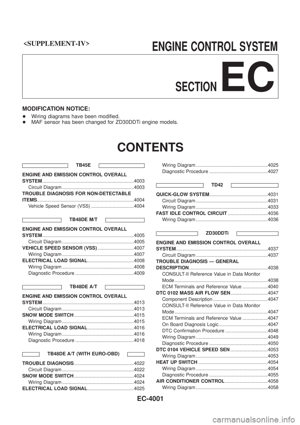
MODIFICATION NOTICE:
+Wiring diagrams have been modi®ed.
+ MAF sensor has been changed for ZD30DDTi engine models.
CONTENTS
TB45E
ENGINE AND EMISSION CONTROL OVERALL
SYSTEM .....................................................................4003
Circuit Diagram ......................................................4003
TROUBLE DIAGNOSIS FOR NON-DETECTABLE
ITEMS ........................................................................\
.4004
Vehicle Speed Sensor (VSS) ................................4004
TB48DE M/T
ENGINE AND EMISSION CONTROL OVERALL
SYSTEM.....................................................................4005
Circuit Diagram ......................................................4005
VEHICLE SPEED SENSOR (VSS) ...........................4007
Wiring Diagram ......................................................4007
ELECTRICAL LOAD SIGNAL ...................................4008
Wiring Diagram ......................................................4008
Diagnostic Procedure ............................................4009
TB48DE A/T
ENGINE AND EMISSION CONTROL OVERALL
SYSTEM.....................................................................4013
Circuit Diagram ......................................................4013
SNOW MODE SWITCH .............................................4015
Wiring Diagram ......................................................4015
ELECTRICAL LOAD SIGNAL ...................................4016
Wiring Diagram ......................................................4016
Diagnostic Procedure ............................................4018
TB48DE A/T (WITH EURO-OBD)
TROUBLE DIAGNOSIS .............................................4022
Circuit Diagram ......................................................4022
SNOW MODE SWITCH .............................................4024
Wiring Diagram ......................................................4024
ELECTRICAL LOAD SIGNAL ...................................4025 Wiring Diagram ......................................................4025
Diagnostic Procedure ............................................4027
TD42
QUICK-GLOW SYSTEM ............................................4031
Circuit Diagram ......................................................4031
Wiring Diagram ......................................................4033
FAST IDLE CONTROL CIRCUIT ..............................4036
Wiring Diagram ......................................................4036
ZD30DDTi
ENGINE AND EMISSION CONTROL OVERALL
SYSTEM.....................................................................4037
Circuit Diagram ......................................................4037
TROUBLE DIAGNOSIS Ð GENERAL
DESCRIPTION ...........................................................4038
CONSULT-II Reference Value in Data Monitor
Mode ......................................................................4038
ECM Terminals and Reference Value ...................4040
DTC 0102 MASS AIR FLOW SEN ............................4047
Component Description .........................................4047
CONSULT-II Reference Value in Data Monitor
Mode ......................................................................4047
ECM Terminals and Reference Value ...................4047
On Board Diagnosis Logic.....................................4047
DTC Con®rmation Procedure ................................4048
Wiring Diagram ......................................................4049
Diagnostic Procedure ............................................4050
DTC 0104 VEHICLE SPEED SEN ............................4053
Wiring Diagram ......................................................4053
HEAT UP SWITCH ....................................................4054
Wiring Diagram ......................................................4054
Diagnostic Procedure ............................................4055
AIR CONDITIONER CONTROL ................................4058
Wiring Diagram ......................................................4058
EC-4001
Page 37 of 579
TD42Ti
ENGINE AND EMISSION CONTROL OVERALL
SYSTEM.....................................................................4059
Circuit Diagram ......................................................4059TROUBLE DIAGNOSES FOR NON-DETECTABLE
ITEMS.........................................................................4060
Vehicle Speed Sensor (VSS) ................................4060
When you read wiring diagrams:
+Read GI section, ªHOW TO READ WIRING DIAGRAMSº.
+See EL section, ªPOWER SUPPLY ROUTINGº for power distribution circuit.
When you perform trouble diagnoses, read GI section, ªHOW TO FOLLOW FLOW CHART IN
TROUBLE DIAGNOSESº and ªHOW TO PERFORM EFFICIENT DIAGNOSIS FOR AN ELECTRICAL
INCIDENTº.
CONTENTS(Cont'd)
EC-4002
Page 38 of 579

Circuit Diagram
TEC515M
ENGINE AND EMISSION CONTROL OVERALL SYSTEMTB45E
EC-4003
Page 39 of 579

Vehicle Speed Sensor (VSS)
TEC532M
TROUBLE DIAGNOSIS FOR NON-DETECTABLE ITEMSTB45E
EC-4004
Page 40 of 579

Circuit Diagram
TEC516M
ENGINE AND EMISSION CONTROL OVERALL
SYSTEMTB48DE M/T
EC-4005