NISSAN PATROL 2006 Service Manual
PATROL 2006
NISSAN
NISSAN
https://www.carmanualsonline.info/img/5/57368/w960_57368-0.png
NISSAN PATROL 2006 Service Manual
Trending: radiator cap, spare wheel, Heating, coolant level, changing engine coolant, air suspension, roof
Page 761 of 1226
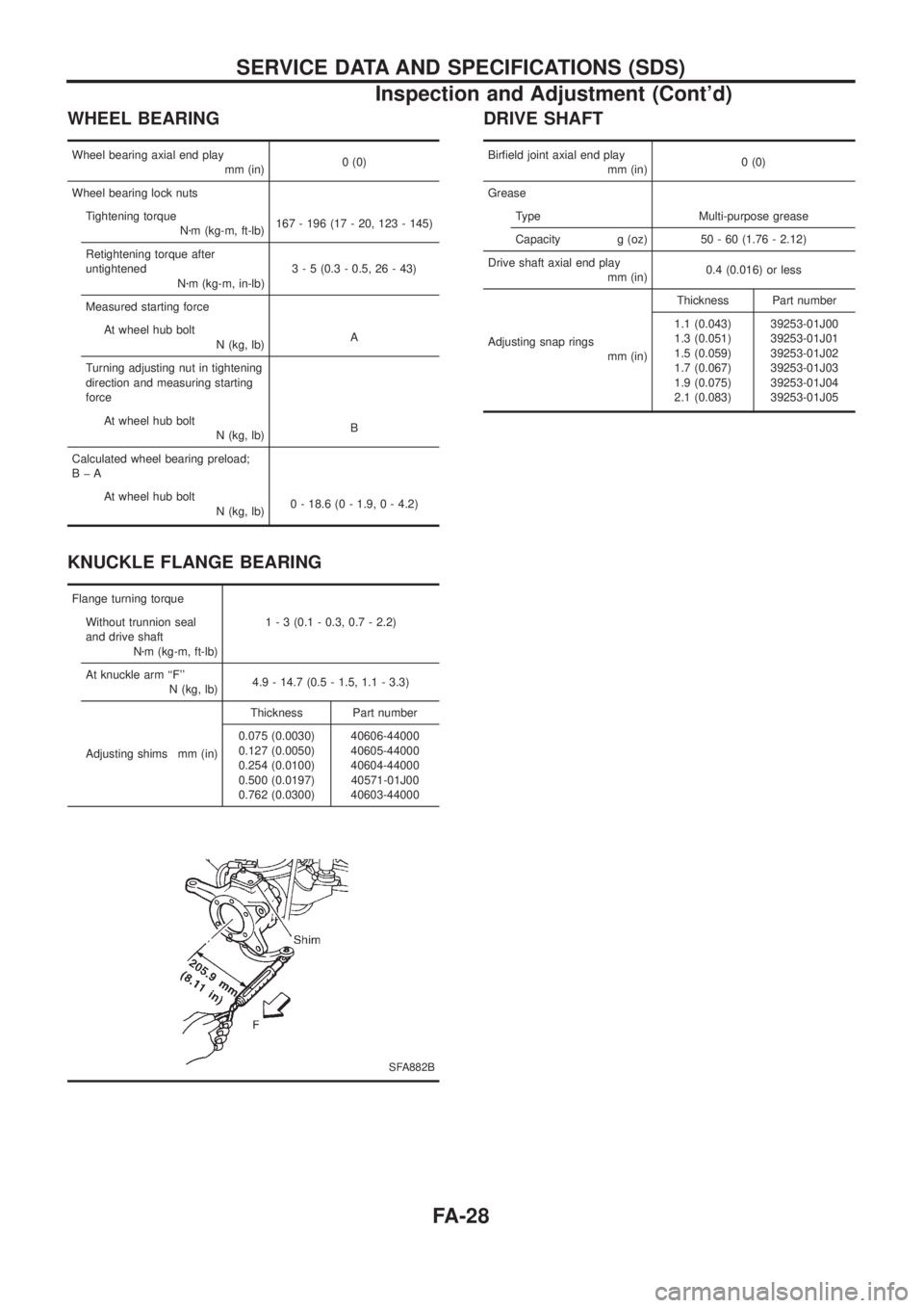
WHEEL BEARING
Wheel bearing axial end play
mm (in)0 (0)
Wheel bearing lock nuts
Tightening torque
Nzm (kg-m, ft-lb)167 - 196 (17 - 20, 123 - 145)
Retightening torque after
untightened
Nzm (kg-m, in-lb)3 - 5 (0.3 - 0.5, 26 - 43)
Measured starting force
At wheel hub bolt
N (kg, lb)A
Turning adjusting nut in tightening
direction and measuring starting
force
At wheel hub bolt
N (kg, lb)B
Calculated wheel bearing preload;
BþA
At wheel hub bolt
N (kg, lb)0 - 18.6 (0 - 1.9, 0 - 4.2)
KNUCKLE FLANGE BEARING
Flange turning torque
Without trunnion seal
and drive shaft
Nzm (kg-m, ft-lb)1 - 3 (0.1 - 0.3, 0.7 - 2.2)
At knuckle arm ``F''
N (kg, lb)4.9 - 14.7 (0.5 - 1.5, 1.1 - 3.3)
Adjusting shims mm (in)Thickness Part number
0.075 (0.0030)
0.127 (0.0050)
0.254 (0.0100)
0.500 (0.0197)
0.762 (0.0300)40606-44000
40605-44000
40604-44000
40571-01J00
40603-44000
SFA882B
DRIVE SHAFT
Bir®eld joint axial end play
mm (in)0 (0)
Grease
Type Multi-purpose grease
Capacity g (oz) 50 - 60 (1.76 - 2.12)
Drive shaft axial end play
mm (in)0.4 (0.016) or less
Adjusting snap rings
mm (in)Thickness Part number
1.1 (0.043)
1.3 (0.051)
1.5 (0.059)
1.7 (0.067)
1.9 (0.075)
2.1 (0.083)39253-01J00
39253-01J01
39253-01J02
39253-01J03
39253-01J04
39253-01J05
SERVICE DATA AND SPECIFICATIONS (SDS)
Inspection and Adjustment (Cont'd)
FA-28
Page 762 of 1226
ACCELERATOR CONTROL, FUEL &
EXHAUST SYSTEMS
SECTION
FE
CONTENTS
ACCELERATOR CONTROL SYSTEM...........................1
Accelerator Control System .........................................1FUEL SYSTEM................................................................2
EXHAUST SYSTEM........................................................3
FE
Page 763 of 1226
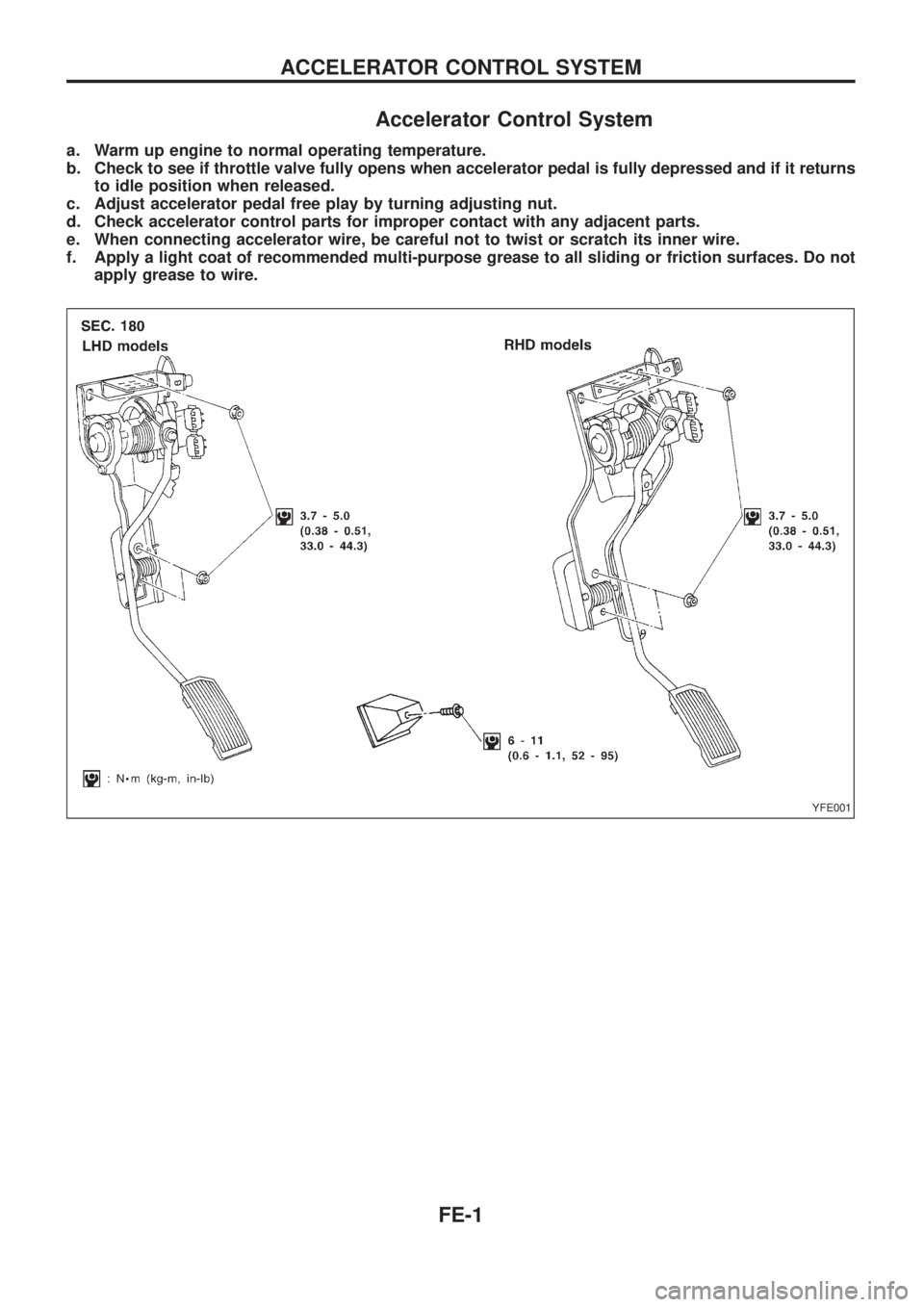
Accelerator Control System
a. Warm up engine to normal operating temperature.
b. Check to see if throttle valve fully opens when accelerator pedal is fully depressed and if it returns
to idle position when released.
c. Adjust accelerator pedal free play by turning adjusting nut.
d. Check accelerator control parts for improper contact with any adjacent parts.
e. When connecting accelerator wire, be careful not to twist or scratch its inner wire.
f. Apply a light coat of recommended multi-purpose grease to all sliding or friction surfaces. Do not
apply grease to wire.
YFE001
ACCELERATOR CONTROL SYSTEM
FE-1
Page 764 of 1226
Page 765 of 1226
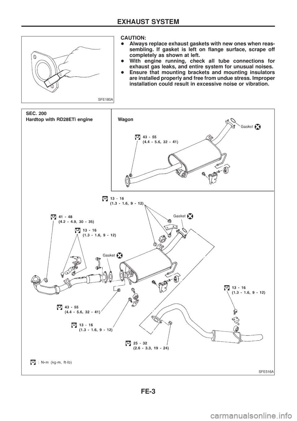
CAUTION:
+Always replace exhaust gaskets with new ones when reas-
sembling. If gasket is left on ¯ange surface, scrape off
completely as shown at left.
+With engine running, check all tube connections for
exhaust gas leaks, and entire system for unusual noises.
+Ensure that mounting brackets and mounting insulators
are installed properly and free from undue stress. Improper
installation could result in excessive noise or vibration.
SFE180A
SFE516A
EXHAUST SYSTEM
FE-3
Page 766 of 1226
PLEASE HELP US TO IMPROVE THIS
SERVICE MANUAL ON CD!
Your comments are important to NISSAN and will help us to improve our
Service Manuals on CD. Use this form to report any issues or comments you
may have regarding this Service Manual publication.
Please print this form and type or print your comments below. Mail or fax to:
NISSAN EUROPE S.A.S.
S320 Service Engineering
2, Avenue de Denis Papin
ZIPEC - F92350 Le Plessis Robinson
France
Fax: + 33(0)141071681
SERVICE MANUAL: Model:Language:
Publication Number:
Please describe any issues or problems in detail:
Page number(s):
Note: Please include a copy of each page, marked with your comments.
Is the organization of the manual clear and easy to follow? (circle your answer) YES NO
Please comment:
What information should be included in NISSAN Service Manuals to better support you in
servicing or repairing customer vehicles?
Date :
Your Name :Position :
Dealer :Dealer No. :
Address :
City :Country :
Telephone :
Fax :
E-mail :
Page 767 of 1226
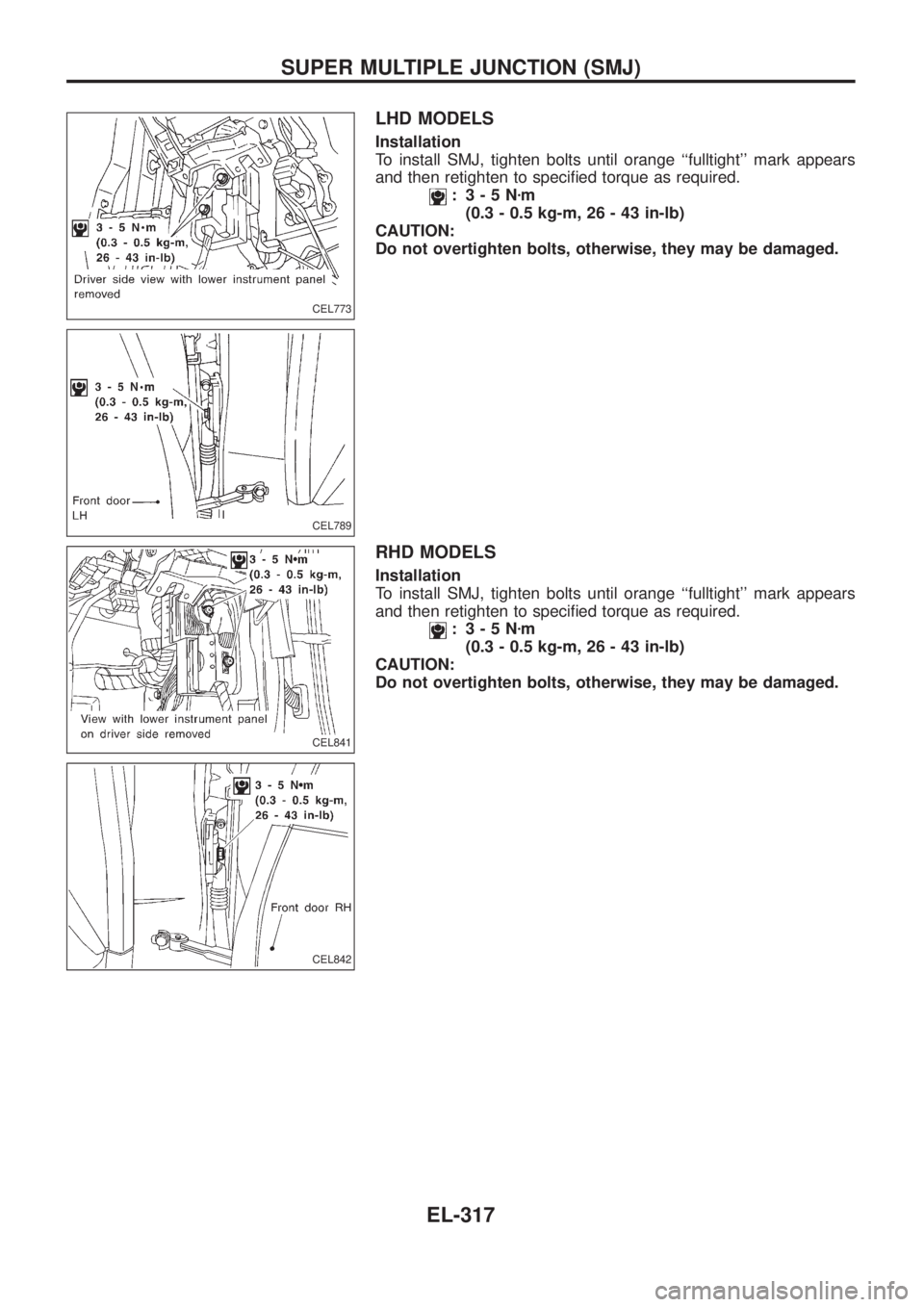
LHD MODELS
Installation
To install SMJ, tighten bolts until orange ``fulltight'' mark appears
and then retighten to speci®ed torque as required.
: 3-5Nzm
(0.3 - 0.5 kg-m, 26 - 43 in-lb)
CAUTION:
Do not overtighten bolts, otherwise, they may be damaged.
RHD MODELS
Installation
To install SMJ, tighten bolts until orange ``fulltight'' mark appears
and then retighten to speci®ed torque as required.
: 3-5Nzm
(0.3 - 0.5 kg-m, 26 - 43 in-lb)
CAUTION:
Do not overtighten bolts, otherwise, they may be damaged.
CEL773
CEL789
CEL841
CEL842
SUPER MULTIPLE JUNCTION (SMJ)
EL-317
Page 768 of 1226
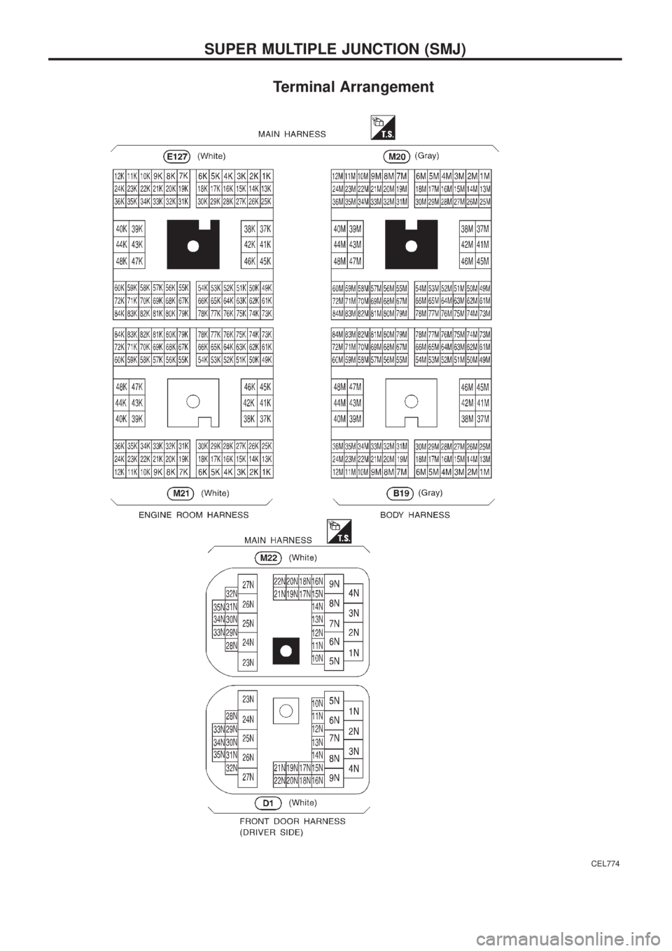
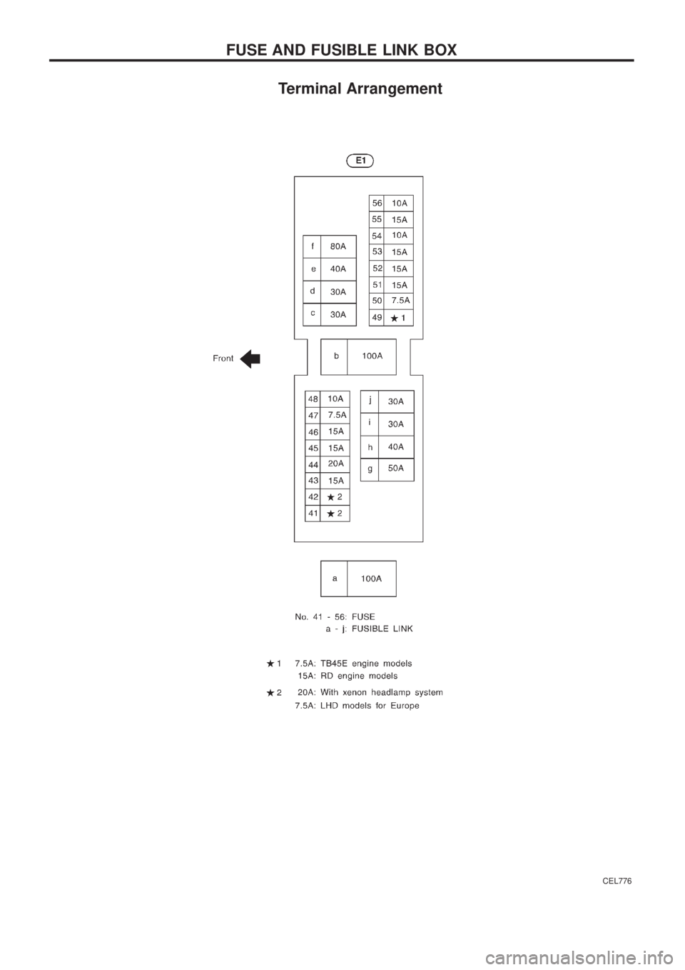
Terminal Arrangement
CEL774
SUPER MULTIPLE JUNCTION (SMJ)
Page 769 of 1226
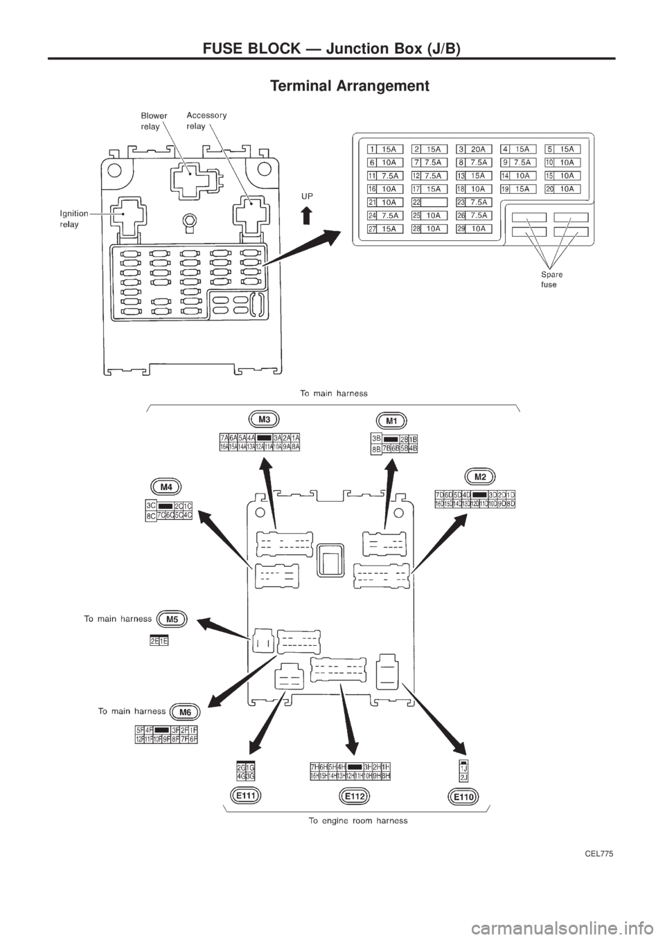
Terminal Arrangement
CEL775
FUSE BLOCK Ð Junction Box (J/B)
Page 770 of 1226
Terminal Arrangement
CEL776
FUSE AND FUSIBLE LINK BOX
Trending: relay, remove seats, alternator belt, torque, wheel bolts, alternator, headlights

