NISSAN PATROL 2006 Service Manual
Manufacturer: NISSAN, Model Year: 2006, Model line: PATROL, Model: NISSAN PATROL 2006Pages: 1226, PDF Size: 37.18 MB
Page 941 of 1226
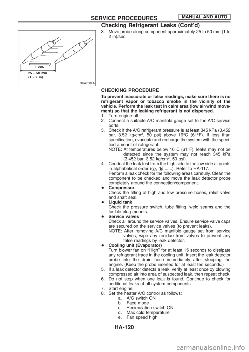
3. Move probe along component approximately 25 to 50 mm (1 to
2 in)/sec.
CHECKING PROCEDURE
To prevent inaccurate or false readings, make sure there is no
refrigerant vapor or tobacco smoke in the vicinity of the
vehicle. Perform the leak test in calm area (low air/wind move-
ment) so that the leaking refrigerant is not dispersed.
1. Turn engine off.
2. Connect a suitable A/C manifold gauge set to the A/C service
ports.
3. Check if the A/C refrigerant pressure is at least 345 kPa (3.452
bar, 3.52 kg/cm
2, 50 psi) above 16ÉC (61ÉF). If less than
speci®cation, evacuate and recharge the system with the speci-
®ed amount of refrigerant.
NOTE: At temperatures below 16ÉC (61ÉF), leaks may not be
detected since the system may not reach 345 kPa
(3.452 bar, 3.52 kg/cm
2, 50 psi).
4. Conduct the leak test from the high side to the low side at points
in alphabetical order (j
a,jb......). Refer to HA-117.
Perform a leak check for the following areas carefully. Clean the
component to be checked and move the leak detector probe
completely around the connection/component.
+Compressor
Check the ®tting of high and low pressure hoses, relief valve
and shaft seal.
+Liquid tank
Check the pressure switch, tube ®tting, weld seams and the
fusible plug mounts.
+Service valves
Check all around the service valves. Ensure service valve caps
are secured on the service valves (to prevent leaks).
NOTE: After removing A/C manifold gauge set from service
valves, wipe any residue from valves to prevent any
false readings by leak detector.
+Cooling unit (Evaporator)
Turn blower fan on ``High'' for at least 15 seconds to dissipate
any refrigerant trace in the cooling unit. Insert the leak detector
probe into the drain hose immediately after stopping the
engine. (Keep the probe inserted for at least ten seconds.)
5. If a leak detector detects a leak, verify at least once by blowing
compressed air into area of suspected leak, then repeat check.
6. Do not stop when one leak is found. Continue to check for
additional leaks at all system components.
7. Start engine.
8. Set the heater A/C control as follows:
a. A/C switch ON
b. Face mode
c. Recirculation switch ON
d. Max cold temperature
e. Fan speed high
SHA708EA
SERVICE PROCEDURESMANUAL AND AUTO
Checking Refrigerant Leaks (Cont'd)
HA-120
Page 942 of 1226
9. Run engine at 1,500 rpm for at least 2 minutes.
10. Turn engine off and perform leak check again following steps 4
through 6 above.
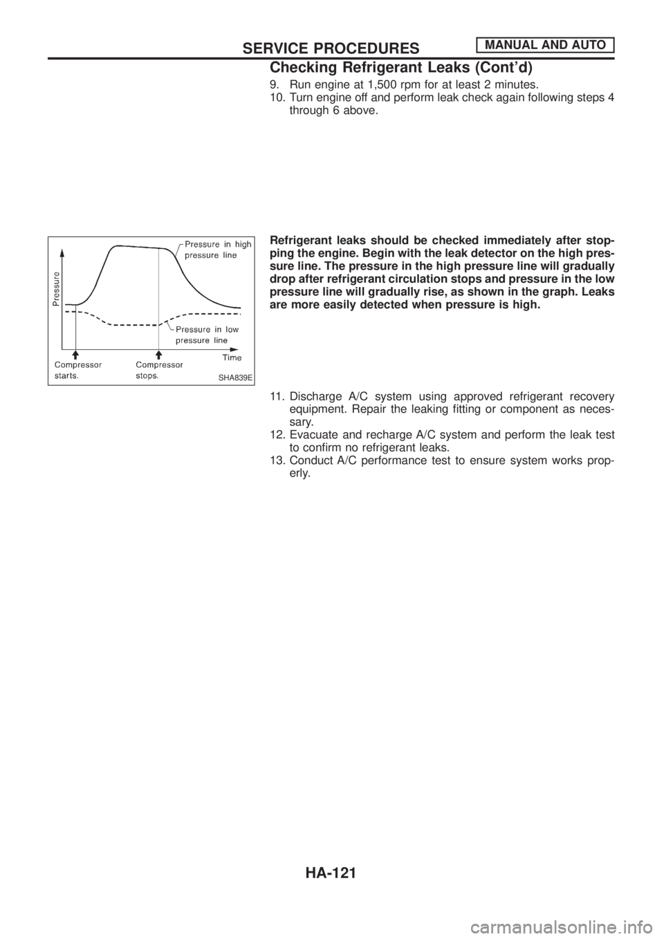
Refrigerant leaks should be checked immediately after stop-
ping the engine. Begin with the leak detector on the high pres-
sure line. The pressure in the high pressure line will gradually
drop after refrigerant circulation stops and pressure in the low
pressure line will gradually rise, as shown in the graph. Leaks
are more easily detected when pressure is high.
11. Discharge A/C system using approved refrigerant recovery
equipment. Repair the leaking ®tting or component as neces-
sary.
12. Evacuate and recharge A/C system and perform the leak test
to con®rm no refrigerant leaks.
13. Conduct A/C performance test to ensure system works prop-
erly.
SHA839E
SERVICE PROCEDURESMANUAL AND AUTO
Checking Refrigerant Leaks (Cont'd)
HA-121
Page 943 of 1226
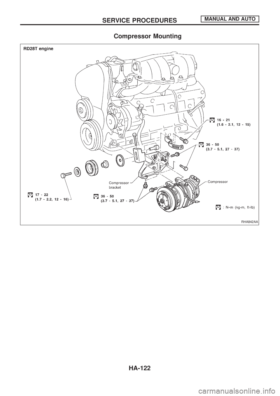
Compressor Mounting
RHA842AA
SERVICE PROCEDURESMANUAL AND AUTO
HA-122
Page 944 of 1226
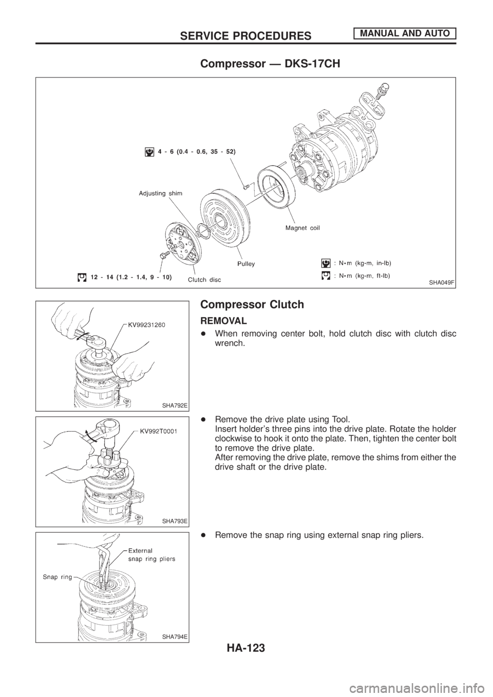
Compressor Ð DKS-17CH
Compressor Clutch
REMOVAL
+When removing center bolt, hold clutch disc with clutch disc
wrench.
+Remove the drive plate using Tool.
Insert holder's three pins into the drive plate. Rotate the holder
clockwise to hook it onto the plate. Then, tighten the center bolt
to remove the drive plate.
After removing the drive plate, remove the shims from either the
drive shaft or the drive plate.
+Remove the snap ring using external snap ring pliers.
SHA049F
SHA792E
SHA793E
SHA794E
SERVICE PROCEDURESMANUAL AND AUTO
HA-123
Page 945 of 1226
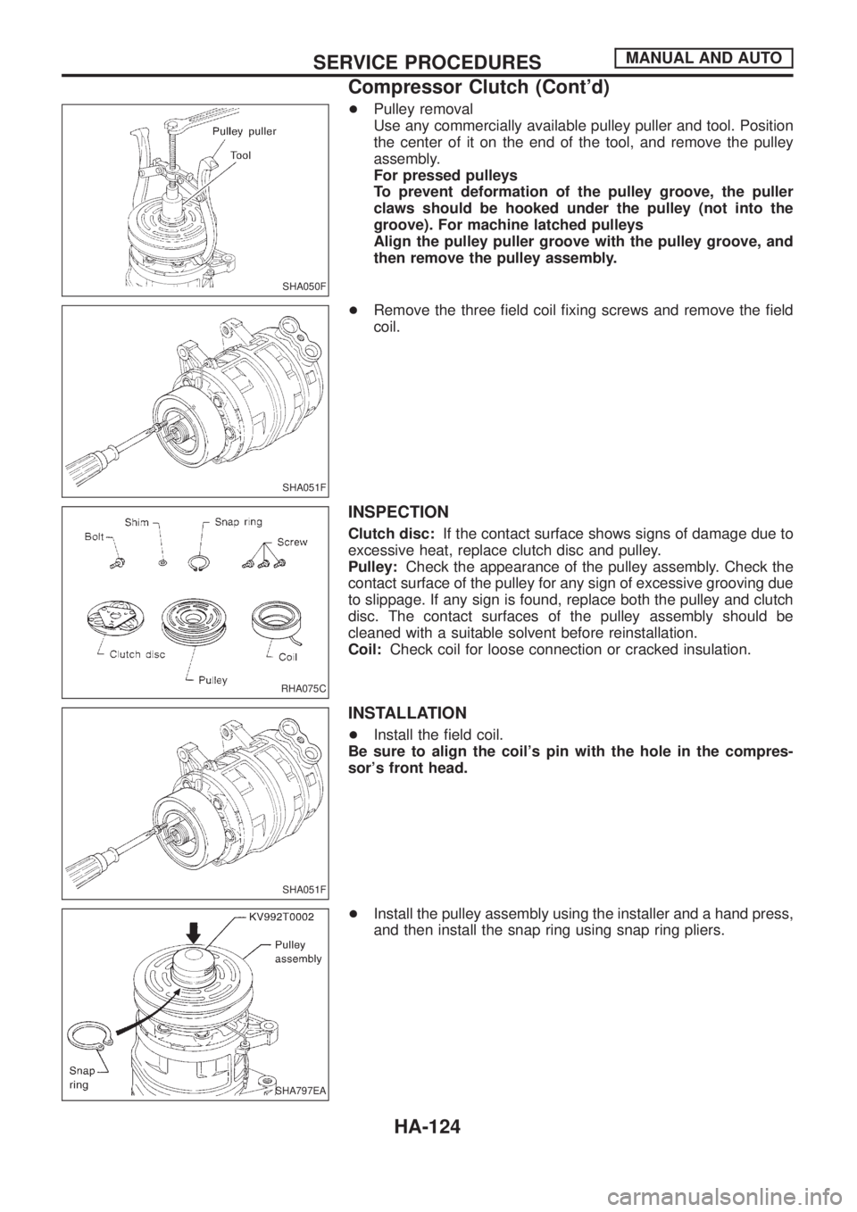
+Pulley removal
Use any commercially available pulley puller and tool. Position
the center of it on the end of the tool, and remove the pulley
assembly.
For pressed pulleys
To prevent deformation of the pulley groove, the puller
claws should be hooked under the pulley (not into the
groove). For machine latched pulleys
Align the pulley puller groove with the pulley groove, and
then remove the pulley assembly.
+Remove the three ®eld coil ®xing screws and remove the ®eld
coil.
INSPECTION
Clutch disc:If the contact surface shows signs of damage due to
excessive heat, replace clutch disc and pulley.
Pulley:Check the appearance of the pulley assembly. Check the
contact surface of the pulley for any sign of excessive grooving due
to slippage. If any sign is found, replace both the pulley and clutch
disc. The contact surfaces of the pulley assembly should be
cleaned with a suitable solvent before reinstallation.
Coil:Check coil for loose connection or cracked insulation.
INSTALLATION
+Install the ®eld coil.
Be sure to align the coil's pin with the hole in the compres-
sor's front head.
+Install the pulley assembly using the installer and a hand press,
and then install the snap ring using snap ring pliers.
SHA050F
SHA051F
RHA075C
SHA051F
SHA797EA
SERVICE PROCEDURESMANUAL AND AUTO
Compressor Clutch (Cont'd)
HA-124
Page 946 of 1226
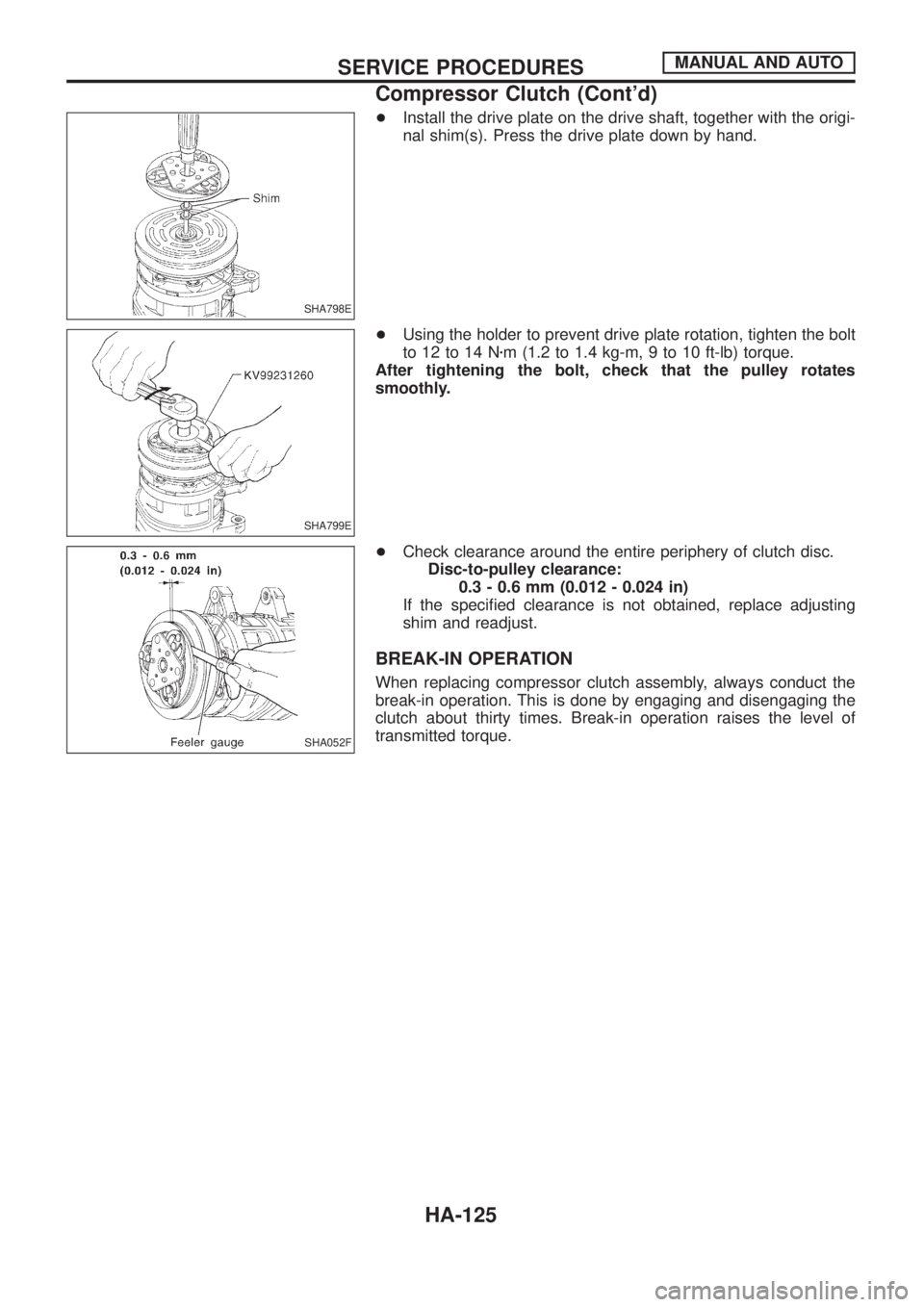
+Install the drive plate on the drive shaft, together with the origi-
nal shim(s). Press the drive plate down by hand.
+Using the holder to prevent drive plate rotation, tighten the bolt
to 12 to 14 Nzm (1.2 to 1.4 kg-m, 9 to 10 ft-lb) torque.
After tightening the bolt, check that the pulley rotates
smoothly.
+Check clearance around the entire periphery of clutch disc.
Disc-to-pulley clearance:
0.3 - 0.6 mm (0.012 - 0.024 in)
If the speci®ed clearance is not obtained, replace adjusting
shim and readjust.
BREAK-IN OPERATION
When replacing compressor clutch assembly, always conduct the
break-in operation. This is done by engaging and disengaging the
clutch about thirty times. Break-in operation raises the level of
transmitted torque.
SHA798E
SHA799E
SHA052F
SERVICE PROCEDURESMANUAL AND AUTO
Compressor Clutch (Cont'd)
HA-125
Page 947 of 1226
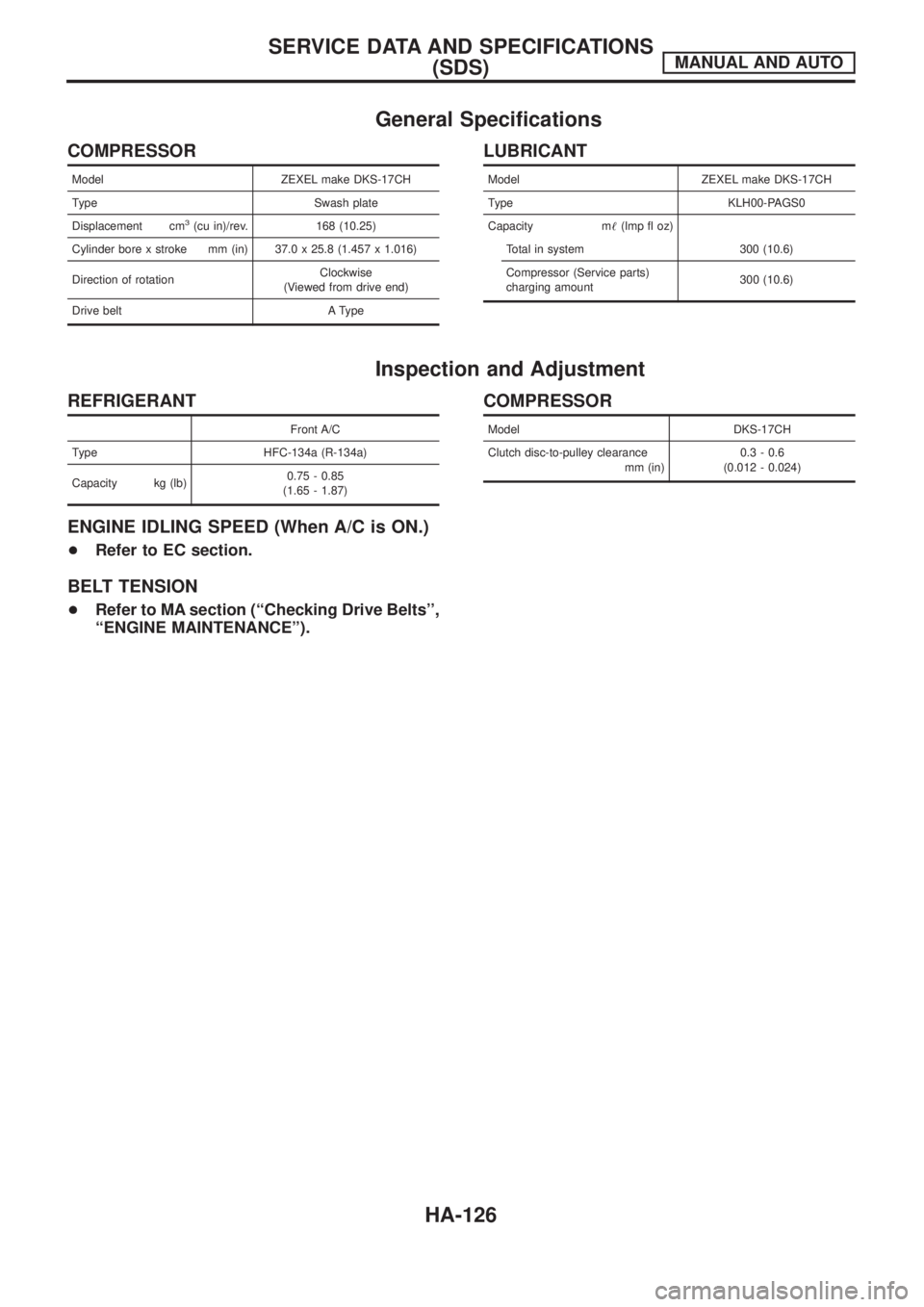
General Speci®cations
COMPRESSOR
Model ZEXEL make DKS-17CH
Type Swash plate
Displacement cm
3(cu in)/rev. 168 (10.25)
Cylinder bore x stroke mm (in) 37.0 x 25.8 (1.457 x 1.016)
Direction of rotationClockwise
(Viewed from drive end)
Drive belt A Type
LUBRICANT
Model ZEXEL make DKS-17CH
Type KLH00-PAGS0
Capacity m!(lmp ¯ oz)
Total in system 300 (10.6)
Compressor (Service parts)
charging amount300 (10.6)
Inspection and Adjustment
REFRIGERANT
Front A/C
Type HFC-134a (R-134a)
Capacity kg (lb)0.75 - 0.85
(1.65 - 1.87)
ENGINE IDLING SPEED (When A/C is ON.)
+Refer to EC section.
BELT TENSION
+Refer to MA section (``Checking Drive Belts'',
``ENGINE MAINTENANCE'').
COMPRESSOR
Model DKS-17CH
Clutch disc-to-pulley clearance
mm (in)0.3 - 0.6
(0.012 - 0.024)
SERVICE DATA AND SPECIFICATIONS
(SDS)MANUAL AND AUTO
HA-126
Page 948 of 1226
ALPHABETICAL INDEX
SECTION
IDX
IDX
Page 949 of 1226
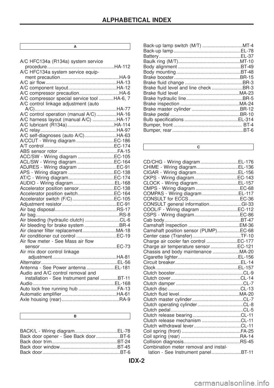
A
A/C HFC134a (R134a) system service
procedure ..................................................HA-112
A/C HFC134a system service equip-
ment precaution ............................................HA-9
A/C air ¯ow .....................................................HA-13
A/C component layout ....................................HA-12
A/C compressor precaution..............................HA-6
A/C compressor special service tool ...........HA-6, 7
A/C control linkage adjustment (auto
A/C).............................................................HA-77
A/C control operation (manual A/C) ...............HA-16
A/C harness layout (manual A/C) ..................HA-17
A/C lubricant (R134a) ...................................HA-114
A/C relay.........................................................HA-97
A/C self-diagnoses (auto A/C)........................HA-63
A/CCUT - Wiring diagram ............................EC-186
A/T control ....................................................EC-174
ABS sensor rotor ............................................FA-15
ACC/SW - Wiring diagram ...........................EC-105
ACL/SW - Wiring diagram ............................EC-164
ADJRES - Wiring diagram .............................EC-91
APS - Wiring diagram ..................................EC-138
AT/C - Wiring diagram..................................EC-174
AUDIO - Wiring diagram ...............................EL-168
Accelerator position sensor ..........................EC-138
Accelerator position switch...........................EC-164
Accelerator switch (F/C) ...............................EC-105
Adjustment resistor.........................................EC-91
Air bag disposal..............................................RS-17
Air bag ..............................................................RS-8
Air bleeding (hydraulic clutch) ..........................CL-6
Air bleeding for brake system ..........................BR-4
Air cleaner ®lter replacement .........................MA-18
Air conditioner cut control ..............................EC-19
Air ¯ow meter - See Mass air ¯ow
sensor .........................................................EC-73
Air mix door control linkage
adjustment ................................................HA-81
Alternator.........................................................EL-56
Antenna - See Power antenna .....................EL-181
Audio and A/C control removal and
installation - See Instrument panel .............BT-11
Audio .............................................................EL-168
Auto lock free running hub .............................FA-13
Automatic ampli®er .........................................HA-61
Axle housing (rear) ...........................................RA-9
B
BACK/L - Wiring diagram................................EL-78
Back door opener - See Back door ..................BT-6
Back door trim.................................................BT-24
Back door window...........................................BT-45
Back door ..........................................................BT-6Back-up lamp switch (M/T) ..............................MT-4
Back-up lamp ..................................................EL-78
Battery .............................................................EL-37
Baulk ring (M/T)..............................................MT-10
Body alignment ...............................................BT-49
Body mounting ................................................BT-48
Brake booster .................................................BR-15
Brake ¯uid change ...........................................BR-3
Brake ¯uid level and line check .......................BR-3
Brake ¯uid level .............................................MA-23
Brake hydraulic line ..........................................BR-5
Brake inspection ............................................MA-24
Brake master cylinder ....................................BR-12
Brake pedal ....................................................BR-10
Bulb speci®cations ........................................EL-314
Bumper, front ................................................... BT-4
Bumper, rear .....................................................BT-6
C
CD/CHG - Wiring diagram ............................EL-176
CHIME - Wiring diagram...............................EL-136
CIGAR - Wiring diagram ...............................EL-156
CKPS - Wiring diagram ................................EC-143
CLOCK - Wiring diagram ..............................EL-157
CMPS - Wiring diagram .................................EC-68
COMPAS - Wiring diagram ...........................EL-117
CONSULT for ECCS ......................................EC-36
CONSULT general information ........................GI-33
COOL/F - Wiring diagram ............................EC-112
CSPS - Wiring diagram ..................................EC-86
Cab body.........................................................BT-47
Camshaft inspection ......................................EM-36
Camshaft position sensor (PUMP).................EC-68
Center case (Transfer) ....................................TF-10
Charge air cooler fan control .......................EC-177
Charge air temperature sensor ....................EC-121
Chassis and body maintenance ....................MA-20
Cigarette lighter.............................................EL-156
Circuit breaker.................................................EL-14
Clock .............................................................EL-157
Clutch booster...................................................CL-9
Clutch cover ....................................................CL-14
Clutch damper ..................................................CL-7
Clutch disc ......................................................CL-13
Clutch ¯uid level.............................................MA-20
Clutch master cylinder ......................................CL-7
Clutch operating cylinder ..................................CL-8
Clutch pedal ......................................................CL-5
Clutch release bearing ....................................CL-11
Clutch release mechanism .............................CL-11
Clutch withdrawal lever ...................................CL-11
Coil spring (front) ............................................FA-25
Coil spring (rear) ............................................RA-14
Collision diagnosis..........................................RS-45
Combination meter removal and instal-
lation - See Instrument panel ......................BT-11
ALPHABETICAL INDEX
IDX-2
Page 950 of 1226
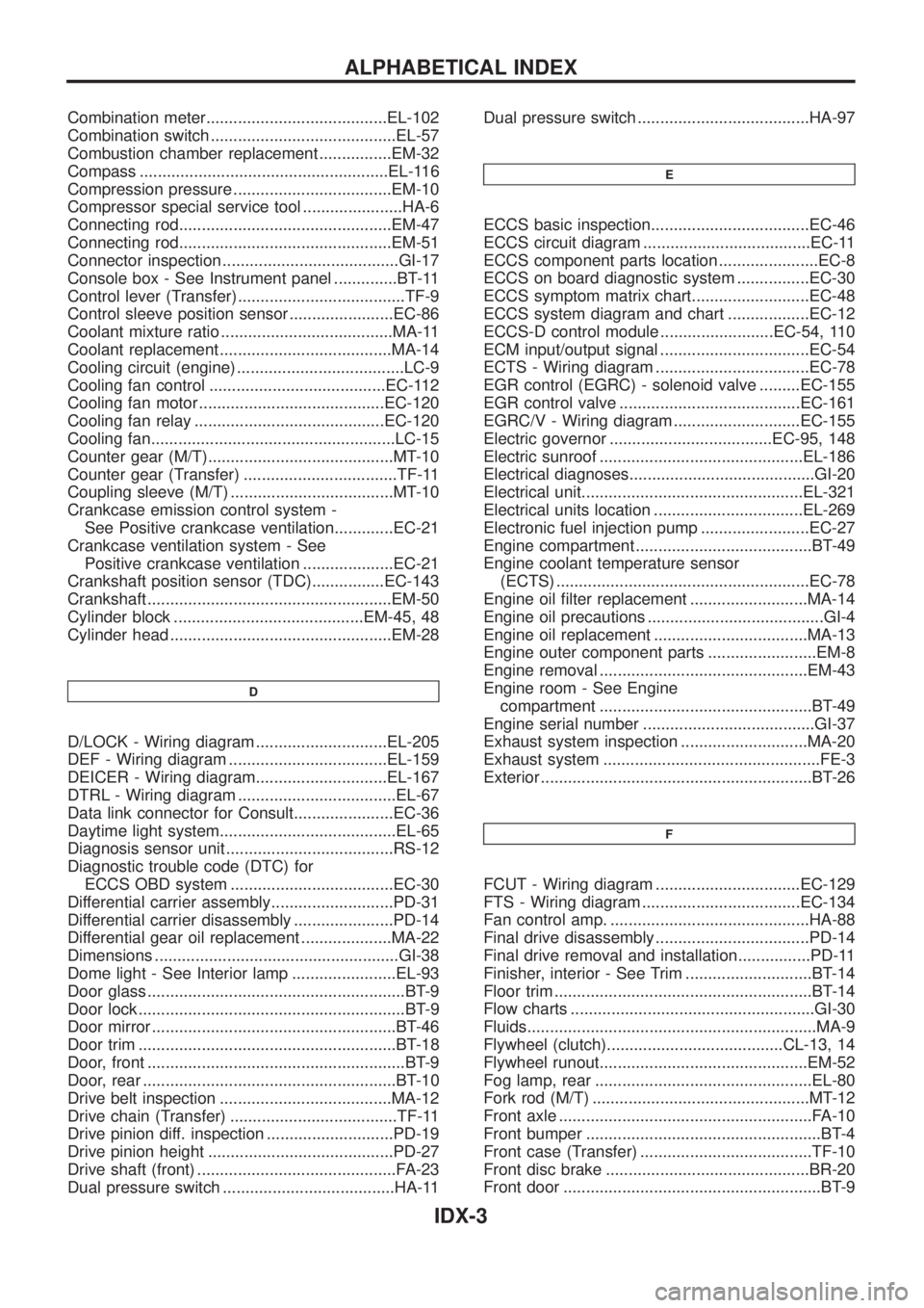
Combination meter........................................EL-102
Combination switch .........................................EL-57
Combustion chamber replacement ................EM-32
Compass .......................................................EL-116
Compression pressure ...................................EM-10
Compressor special service tool ......................HA-6
Connecting rod...............................................EM-47
Connecting rod...............................................EM-51
Connector inspection .......................................GI-17
Console box - See Instrument panel ..............BT-11
Control lever (Transfer) .....................................TF-9
Control sleeve position sensor .......................EC-86
Coolant mixture ratio ......................................MA-11
Coolant replacement ......................................MA-14
Cooling circuit (engine) .....................................LC-9
Cooling fan control .......................................EC-112
Cooling fan motor .........................................EC-120
Cooling fan relay ..........................................EC-120
Cooling fan......................................................LC-15
Counter gear (M/T).........................................MT-10
Counter gear (Transfer) ..................................TF-11
Coupling sleeve (M/T) ....................................MT-10
Crankcase emission control system -
See Positive crankcase ventilation.............EC-21
Crankcase ventilation system - See
Positive crankcase ventilation ....................EC-21
Crankshaft position sensor (TDC)................EC-143
Crankshaft ......................................................EM-50
Cylinder block ..........................................EM-45, 48
Cylinder head .................................................EM-28
D
D/LOCK - Wiring diagram .............................EL-205
DEF - Wiring diagram ...................................EL-159
DEICER - Wiring diagram.............................EL-167
DTRL - Wiring diagram ...................................EL-67
Data link connector for Consult......................EC-36
Daytime light system.......................................EL-65
Diagnosis sensor unit .....................................RS-12
Diagnostic trouble code (DTC) for
ECCS OBD system ....................................EC-30
Differential carrier assembly...........................PD-31
Differential carrier disassembly ......................PD-14
Differential gear oil replacement ....................MA-22
Dimensions ......................................................GI-38
Dome light - See Interior lamp .......................EL-93
Door glass .........................................................BT-9
Door lock ...........................................................BT-9
Door mirror ......................................................BT-46
Door trim .........................................................BT-18
Door, front .........................................................BT-9
Door, rear ........................................................BT-10
Drive belt inspection ......................................MA-12
Drive chain (Transfer) .....................................TF-11
Drive pinion diff. inspection ............................PD-19
Drive pinion height .........................................PD-27
Drive shaft (front) ............................................FA-23
Dual pressure switch ......................................HA-11Dual pressure switch ......................................HA-97
E
ECCS basic inspection...................................EC-46
ECCS circuit diagram .....................................EC-11
ECCS component parts location ......................EC-8
ECCS on board diagnostic system ................EC-30
ECCS symptom matrix chart..........................EC-48
ECCS system diagram and chart ..................EC-12
ECCS-D control module .........................EC-54, 110
ECM input/output signal .................................EC-54
ECTS - Wiring diagram ..................................EC-78
EGR control (EGRC) - solenoid valve .........EC-155
EGR control valve ........................................EC-161
EGRC/V - Wiring diagram ............................EC-155
Electric governor ....................................EC-95, 148
Electric sunroof .............................................EL-186
Electrical diagnoses.........................................GI-20
Electrical unit.................................................EL-321
Electrical units location .................................EL-269
Electronic fuel injection pump ........................EC-27
Engine compartment .......................................BT-49
Engine coolant temperature sensor
(ECTS) ........................................................EC-78
Engine oil ®lter replacement ..........................MA-14
Engine oil precautions .......................................GI-4
Engine oil replacement ..................................MA-13
Engine outer component parts ........................EM-8
Engine removal ..............................................EM-43
Engine room - See Engine
compartment ...............................................BT-49
Engine serial number ......................................GI-37
Exhaust system inspection ............................MA-20
Exhaust system ................................................FE-3
Exterior ............................................................BT-26
F
FCUT - Wiring diagram ................................EC-129
FTS - Wiring diagram ...................................EC-134
Fan control amp. ............................................HA-88
Final drive disassembly ..................................PD-14
Final drive removal and installation................PD-11
Finisher, interior - See Trim ............................BT-14
Floor trim .........................................................BT-14
Flow charts ......................................................GI-30
Fluids................................................................MA-9
Flywheel (clutch).......................................CL-13, 14
Flywheel runout..............................................EM-52
Fog lamp, rear ................................................EL-80
Fork rod (M/T) ................................................MT-12
Front axle ........................................................FA-10
Front bumper ....................................................BT-4
Front case (Transfer) ......................................TF-10
Front disc brake .............................................BR-20
Front door .........................................................BT-9
ALPHABETICAL INDEX
IDX-3