Diff NISSAN PATROL 2006 Service Manual
[x] Cancel search | Manufacturer: NISSAN, Model Year: 2006, Model line: PATROL, Model: NISSAN PATROL 2006Pages: 1226, PDF Size: 37.18 MB
Page 1 of 1226
Edition: February 1998
Release: February 1998 (01)
Publication No.: SM8E-0Y61E0E
Reference No.: 7711346063GENERAL INFORMATIONGI
MAINTENANCEMA
ENGINE MECHANICALEM
ENGINE LUBRICATION &
COOLING SYSTEMSLC
ENGINE CONTROL SYSTEMEC
ACCELERATOR CONTROL,
FUEL & EXHAUST SYSTEMFE
CLUTCHCL
MANUAL TRANSMISSIONMT
AUTOMATIC TRANSMISSIONAT
TRANSFERTF
PROPELLER SHAFT &
DIFFERENTIAL CARRIERPD
FRONT AXLE & FRONT SUSPENSIONFA
REAR AXLE & REAR SUSPENSIONRA
BRAKE SYSTEMBR
STEERING SYSTEMST
RESTRAINT SYSTEMRS
BODY & TRIMBT
HEATER & AIR CONDITIONERHA
ELECTRICAL SYSTEMEL
ALPHABETICAL INDEXIDX
PATROL GR
MODEL Y61 SERIES
NISSAN EUROPE S.A.S.
1998 NISSAN EUROPE S.A.S.
Produced in The Netherlands
Not to be reproduced in whole or in part
without the prior written permission of
Nissan Europe S.A.S., Paris, France.
QUICK REFERENCE INDEX
Page 6 of 1226
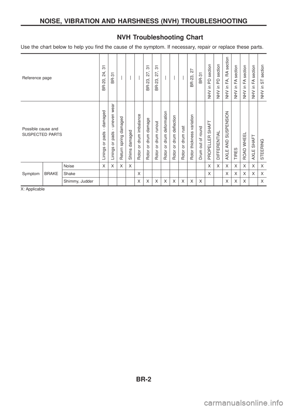
NVH Troubleshooting Chart
Use the chart below to help you ®nd the cause of the symptom. If necessary, repair or replace these parts.
Reference page
BR-20, 24, 31BR-31Ð
Ð
Ð
BR-23, 27, 31
BR-23, 27, 31 Ð
Ð
Ð
BR-23, 27 BR-31
NHV in PD section
NHV in PD section
NHV in FA, RA section
NHV in FA section
NHV in FA section
NHV in FA section
NHV in ST section
Possible cause and
SUSPECTED PARTS
Linings or pads - damaged
Linings or pads - uneven wear
Return spring damaged
Shims damaged
Rotor or drum imbalance
Rotor or drum damage
Rotor or drum runout
Rotor or drum deformation
Rotor or drum de¯ection
Rotor or drum rust
Rotor thickness variation
Drum out of round
PROPELLER SHAFT
DIFFERENTIAL
AXLE AND SUSPENSION
TIRES
ROAD WHEEL
AXLE SHAFT
STEERING
Symptom BRAKE Noise
XXXX XXXXXXX
Shake X X X X X X X
Shimmy, Judder X X XXXXXX XXX X
X: Applicable
NOISE, VIBRATION AND HARSHNESS (NVH) TROUBLESHOOTING
BR-2
Page 17 of 1226
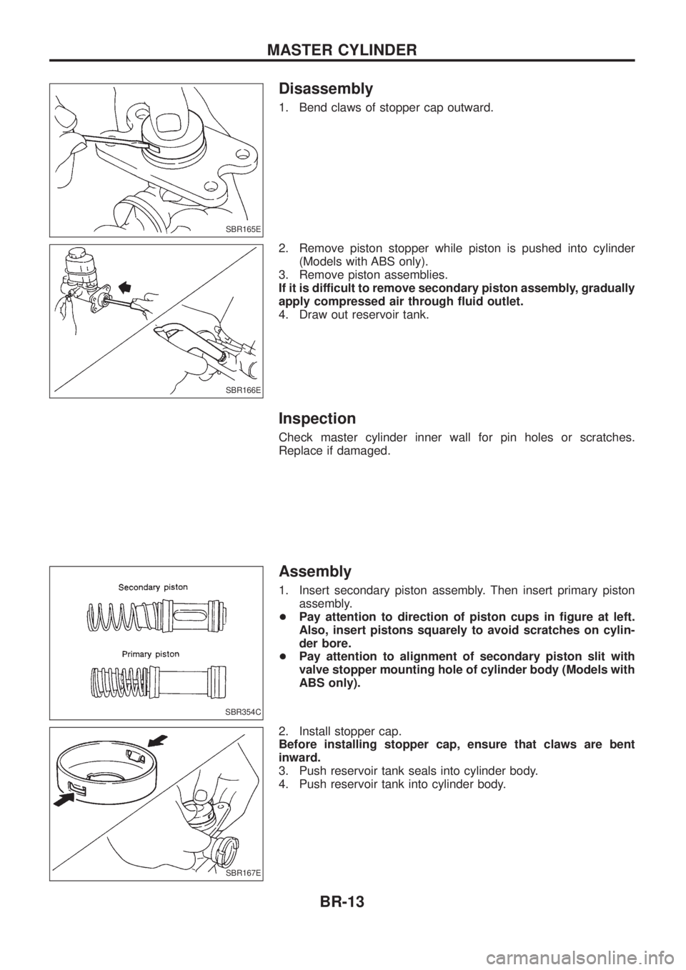
Disassembly
1. Bend claws of stopper cap outward.
2. Remove piston stopper while piston is pushed into cylinder(Models with ABS only).
3. Remove piston assemblies.
If it is difficult to remove secondary piston assembly, gradually
apply compressed air through ¯uid outlet.
4. Draw out reservoir tank.
Inspection
Check master cylinder inner wall for pin holes or scratches.
Replace if damaged.
Assembly
1. Insert secondary piston assembly. Then insert primary piston assembly.
+ Pay attention to direction of piston cups in ®gure at left.
Also, insert pistons squarely to avoid scratches on cylin-
der bore.
+ Pay attention to alignment of secondary piston slit with
valve stopper mounting hole of cylinder body (Models with
ABS only).
2. Install stopper cap.
Before installing stopper cap, ensure that claws are bent
inward.
3. Push reservoir tank seals into cylinder body.
4. Push reservoir tank into cylinder body.
SBR165E
SBR166E
SBR354C
SBR167E
MASTER CYLINDER
BR-13
Page 36 of 1226
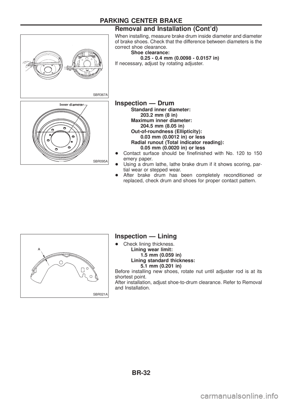
When installing, measure brake drum inside diameter and diameter
of brake shoes. Check that the difference between diameters is the
correct shoe clearance.Shoe clearance:0.25 - 0.4 mm (0.0098 - 0.0157 in)
If necessary, adjust by rotating adjuster.
Inspection Ð Drum
Standard inner diameter: 203.2 mm (8 in)
Maximum inner diameter: 204.5 mm (8.05 in)
Out-of-roundness (Ellipticity): 0.03 mm (0.0012 in) or less
Radial runout (Total indicator reading): 0.05 mm (0.0020 in) or less
+ Contact surface should be ®ne®nished with No. 120 to 150
emery paper.
+ Using a drum lathe, lathe brake drum if it shows scoring, par-
tial wear or stepped wear.
+ After brake drum has been completely reconditioned or
replaced, check drum and shoes for proper contact pattern.
Inspection Ð Lining
+Check lining thickness.
Lining wear limit: 1.5 mm (0.059 in)
Lining standard thickness: 5.1 mm (0.201 in)
Before installing new shoes, rotate nut until adjuster rod is at its
shortest point.
After installation, adjust shoe-to-drum clearance. Refer to Removal
and Installation.
SBR367A
SBR095A
SBR021A
PARKING CENTER BRAKE
Removal and Installation (Cont'd)
BR-32
Page 37 of 1226
Purpose
The Anti-Lock Brake System (ABS) consists of electronic and hydraulic components. It allows for control of
braking force so locking of the wheels can be avoided.
The ABS:
1) Improves proper tracking performance through steering wheel operation.
2) Eases obstacle avoidance through steering wheel operation.
3) Improves vehicle stability.
Operation
+When the vehicle speed is less than 10 km/h (6 MPH) this system does not work.
+ The Anti-Lock Brake System (ABS) has a self-test function. The system turns on the ABS warning lamp
for 1 second each time the ignition switch is turned ``ON''. After the engine is started, the ABS warning
lamp turns off. The system performs a test the ®rst time the vehicle reaches 6 km/h (4 MPH). A mechani-
cal noise may be heard as the ABS performs this self-test. This is a normal part of the self-test feature. If
a malfunction is found during this check, the ABS warning lamp will stay on.
+ While driving, a mechanical noise may be heard during ABS operation. This is a normal condition.
+ While DIFF-LOCK is on, the anti-lock brake warning light ¯ashes. This indicates that anti-lock may not be
fully operated. (ABS only)
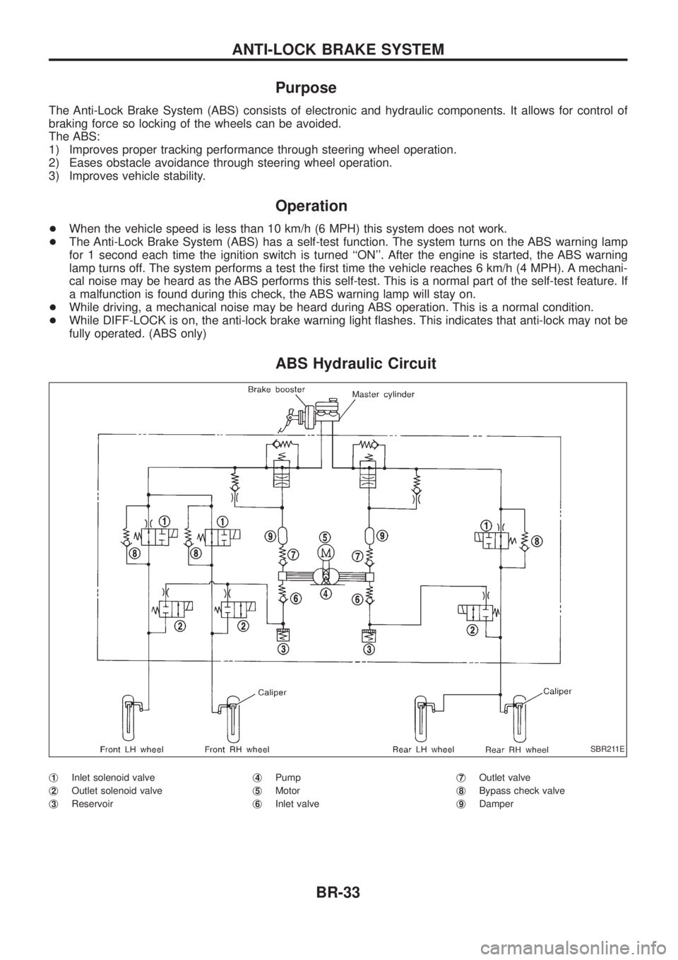
ABS Hydraulic Circuit
j1Inlet solenoid valve
j
2Outlet solenoid valve
j
3Reservoir j
4Pump
j
5Motor
j
6Inlet valve j
7Outlet valve
j
8Bypass check valve
j
9Damper
SBR211E
ANTI-LOCK BRAKE SYSTEM
BR-33
Page 43 of 1226
How to Perform Trouble Diagnoses for Quick
and Accurate Repair
INTRODUCTION
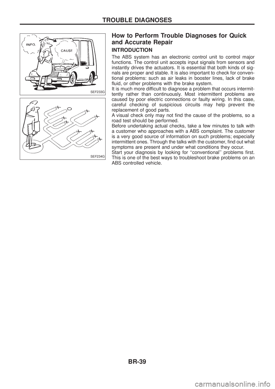
The ABS system has an electronic control unit to control major
functions. The control unit accepts input signals from sensors and
instantly drives the actuators. It is essential that both kinds of sig-
nals are proper and stable. It is also important to check for conven-
tional problems: such as air leaks in booster lines, lack of brake
¯uid, or other problems with the brake system.
It is much more difficult to diagnose a problem that occurs intermit-
tently rather than continuously. Most intermittent problems are
caused by poor electric connections or faulty wiring. In this case,
careful checking of suspicious circuits may help prevent the
replacement of good parts.
A visual check only may not ®nd the cause of the problems, so a
road test should be performed.
Before undertaking actual checks, take a few minutes to talk with
a customer who approaches with a ABS complaint. The customer
is a very good source of information on such problems; especially
intermittent ones. Through the talks with the customer, ®nd out what
symptoms are present and under what conditions they occur.
Start your diagnosis by looking for ``conventional'' problems ®rst.
This is one of the best ways to troubleshoot brake problems on an
ABS controlled vehicle.
SEF233G
SEF234G
TROUBLE DIAGNOSES
BR-39
Page 51 of 1226
Self-diagnosis
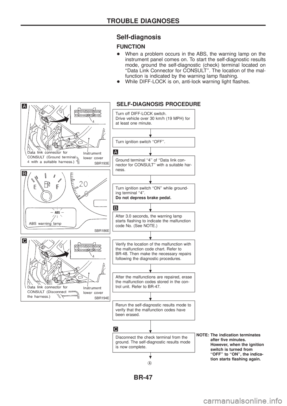
FUNCTION
+When a problem occurs in the ABS, the warning lamp on the
instrument panel comes on. To start the self-diagnostic results
mode, ground the self-diagnostic (check) terminal located on
``Data Link Connector for CONSULT''. The location of the mal-
function is indicated by the warning lamp ¯ashing.
+ While DIFF-LOCK is on, anti-lock warning light ¯ashes.
SELF-DIAGNOSIS PROCEDURE
Turn off DIFF-LOCK switch.
Drive vehicle over 30 km/h (19 MPH) for
at least one minute.
Turn ignition switch ``OFF''.
Ground terminal ``4'' of ``Data link con-
nector for CONSULT'' with a suitable har-
ness.
Turn ignition switch ``ON'' while ground-
ing terminal ``4''.
Do not depress brake pedal.
After 3.0 seconds, the warning lamp
starts ¯ashing to indicate the malfunction
code No. (See NOTE.)
Verify the location of the malfunction with
the malfunction code chart. Refer to
BR-48. Then make the necessary repairs
following the diagnostic procedures.
After the malfunctions are repaired, erase
the malfunction codes stored in the con-
trol unit. Refer to BR-47.
Rerun the self-diagnostic results mode to
verify that the malfunction codes have
been erased.
Disconnect the check terminal from the
ground. The self-diagnostic results mode
is now complete.NOTE: The indication terminates
after ®ve minutes.
However, when the ignition
switch is turned from
``OFF'' to ``ON'', the indica-
tion starts ¯ashing again.
j
A
SBR193E
SBR186E
SBR194E
.
.
.
.
.
.
.
.
.
TROUBLE DIAGNOSES
BR-47
Page 168 of 1226
FUEL TEMPERATURE COMPENSATION
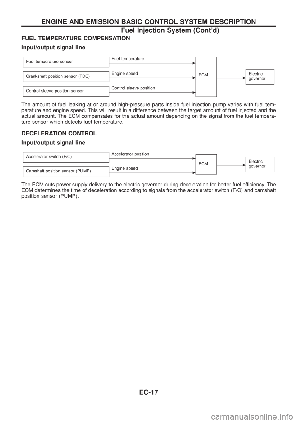
Input/output signal line
Fuel temperature sensorcFuel temperature
ECM
cElectric
governorCrankshaft position sensor (TDC)cEngine speed
Control sleeve position sensor
cControl sleeve position
The amount of fuel leaking at or around high-pressure parts inside fuel injection pump varies with fuel tem-
perature and engine speed. This will result in a difference between the target amount of fuel injected and the
actual amount. The ECM compensates for the actual amount depending on the signal from the fuel tempera-
ture sensor which detects fuel temperature.
DECELERATION CONTROL
Input/output signal line
Accelerator switch (F/C)cAccelerator position
ECM
cElectric
governor
Camshaft position sensor (PUMP)cEngine speed
The ECM cuts power supply delivery to the electric governor during deceleration for better fuel efficiency. The
ECM determines the time of deceleration according to signals from the accelerator switch (F/C) and camshaft
position sensor (PUMP).
ENGINE AND EMISSION BASIC CONTROL SYSTEM DESCRIPTION
Fuel Injection System (Cont'd)
EC-17
Page 171 of 1226
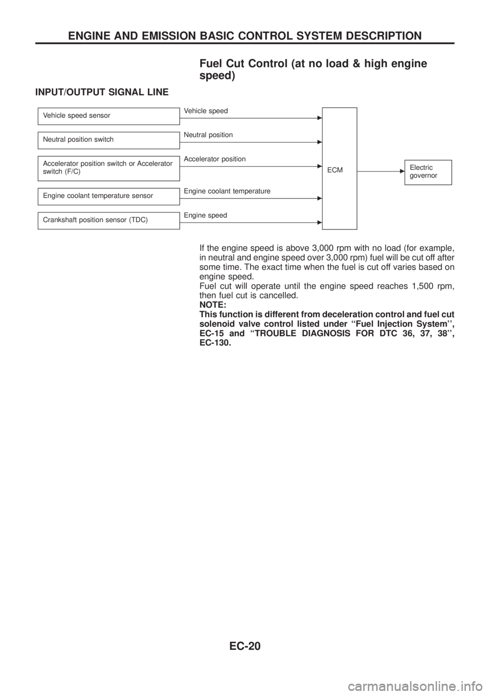
Fuel Cut Control (at no load & high engine
speed)
INPUT/OUTPUT SIGNAL LINE
Vehicle speed sensorcVehicle speed
ECM
cElectric
governor
Neutral position switchcNeutral position
Accelerator position switch or Accelerator
switch (F/C)
cAccelerator position
Engine coolant temperature sensor
cEngine coolant temperature
Crankshaft position sensor (TDC)
cEngine speed
If the engine speed is above 3,000 rpm with no load (for example,
in neutral and engine speed over 3,000 rpm) fuel will be cut off after
some time. The exact time when the fuel is cut off varies based on
engine speed.
Fuel cut will operate until the engine speed reaches 1,500 rpm,
then fuel cut is cancelled.
NOTE:
This function is different from deceleration control and fuel cut
solenoid valve control listed under ``Fuel Injection System'',
EC-15 and ``TROUBLE DIAGNOSIS FOR DTC 36, 37, 38'',
EC-130.
ENGINE AND EMISSION BASIC CONTROL SYSTEM DESCRIPTION
EC-20
Page 176 of 1226
Test and Adjustment
WARNING:
When using nozzle tester, be careful not to allow diesel fuel
sprayed from nozzle to contact your hands or body, and make
sure your eyes are properly protected with goggles.
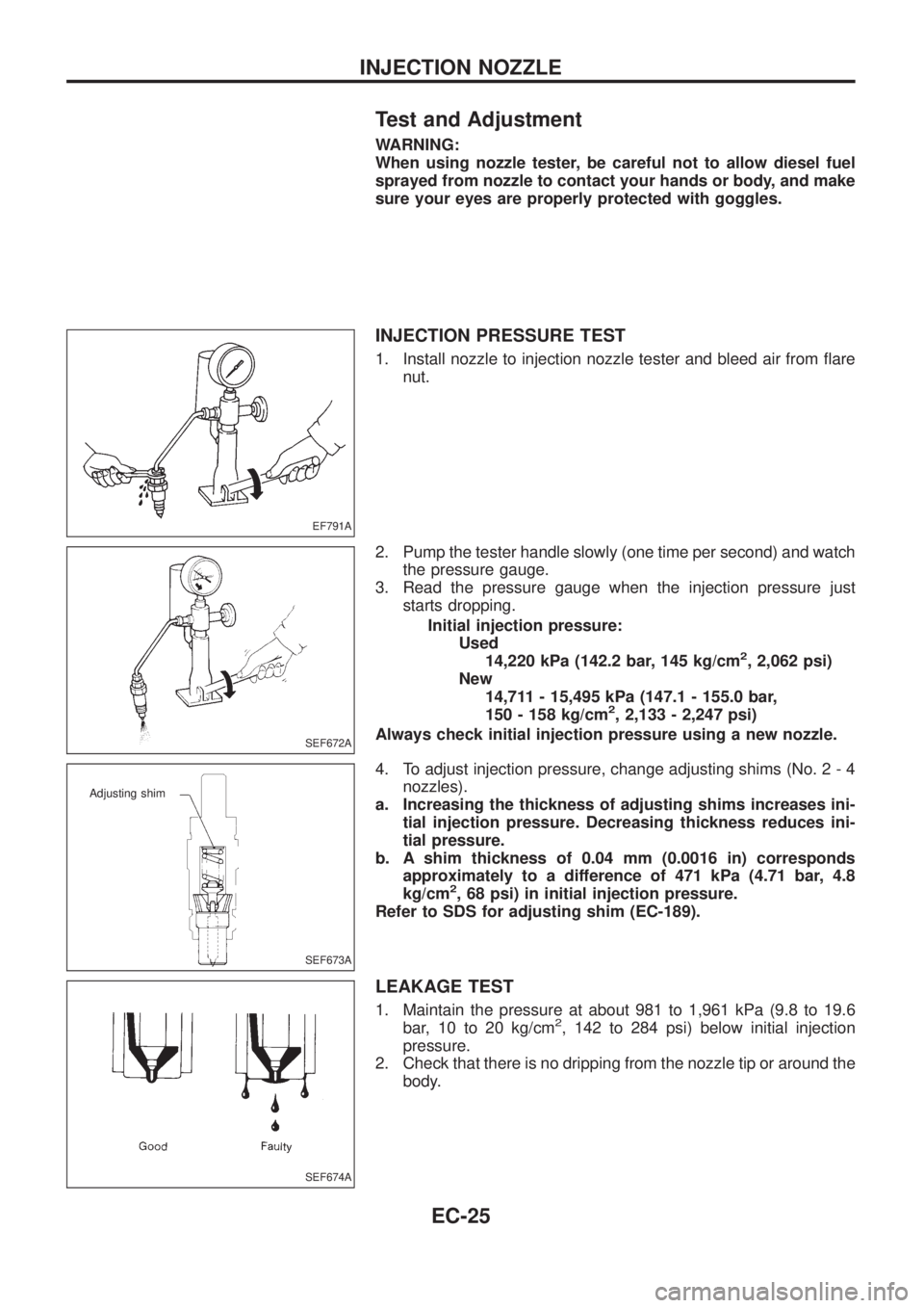
INJECTION PRESSURE TEST
1. Install nozzle to injection nozzle tester and bleed air from ¯are
nut.
2. Pump the tester handle slowly (one time per second) and watch
the pressure gauge.
3. Read the pressure gauge when the injection pressure just
starts dropping.
Initial injection pressure:
Used
14,220 kPa (142.2 bar, 145 kg/cm
2, 2,062 psi)
New
14,711 - 15,495 kPa (147.1 - 155.0 bar,
150 - 158 kg/cm
2, 2,133 - 2,247 psi)
Always check initial injection pressure using a new nozzle.
4. To adjust injection pressure, change adjusting shims (No. 2 - 4
nozzles).
a. Increasing the thickness of adjusting shims increases ini-
tial injection pressure. Decreasing thickness reduces ini-
tial pressure.
b. A shim thickness of 0.04 mm (0.0016 in) corresponds
approximately to a difference of 471 kPa (4.71 bar, 4.8
kg/cm
2, 68 psi) in initial injection pressure.
Refer to SDS for adjusting shim (EC-189).
LEAKAGE TEST
1. Maintain the pressure at about 981 to 1,961 kPa (9.8 to 19.6
bar, 10 to 20 kg/cm2, 142 to 284 psi) below initial injection
pressure.
2. Check that there is no dripping from the nozzle tip or around the
body.
EF791A
SEF672A
SEF673A
Adjusting shim
SEF674A
INJECTION NOZZLE
EC-25