remote control NISSAN PATROL 2006 Service Manual
[x] Cancel search | Manufacturer: NISSAN, Model Year: 2006, Model line: PATROL, Model: NISSAN PATROL 2006Pages: 1226, PDF Size: 37.18 MB
Page 344 of 1226
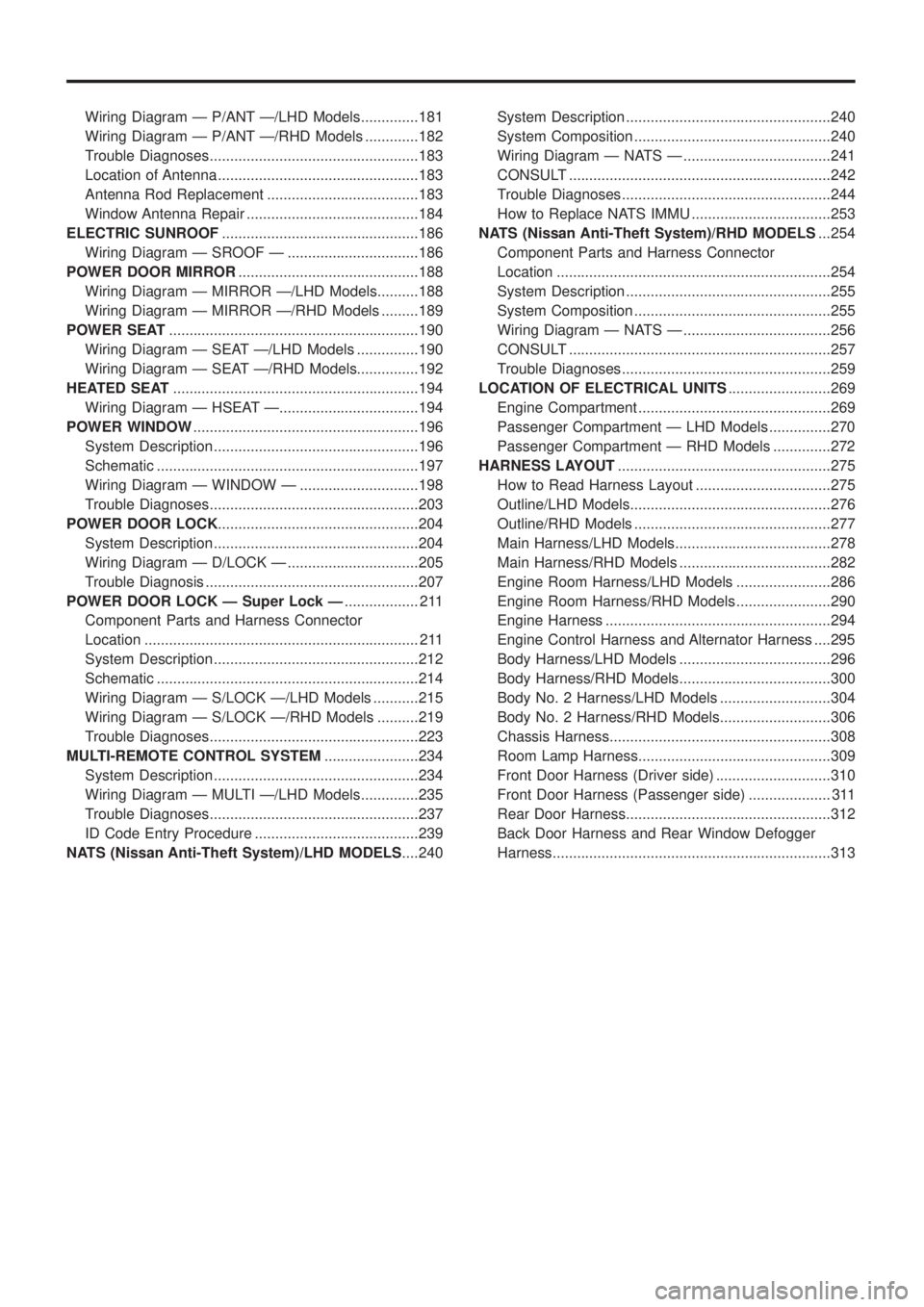
Wiring Diagram Ð P/ANT Ð/LHD Models..............181
Wiring Diagram Ð P/ANT Ð/RHD Models .............182
Trouble Diagnoses...................................................183
Location of Antenna .................................................183
Antenna Rod Replacement .....................................183
Window Antenna Repair ..........................................184
ELECTRIC SUNROOF................................................186
Wiring Diagram Ð SROOF Ð ................................186
POWER DOOR MIRROR............................................188
Wiring Diagram Ð MIRROR Ð/LHD Models..........188
Wiring Diagram Ð MIRROR Ð/RHD Models .........189
POWER SEAT.............................................................190
Wiring Diagram Ð SEAT Ð/LHD Models ...............190
Wiring Diagram Ð SEAT Ð/RHD Models...............192
HEATED SEAT............................................................194
Wiring Diagram Ð HSEAT Ð..................................194
POWER WINDOW.......................................................196
System Description ..................................................196
Schematic ................................................................197
Wiring Diagram Ð WINDOW Ð .............................198
Trouble Diagnoses...................................................203
POWER DOOR LOCK.................................................204
System Description ..................................................204
Wiring Diagram Ð D/LOCK Ð ................................205
Trouble Diagnosis ....................................................207
POWER DOOR LOCK Ð Super Lock Ð.................. 211
Component Parts and Harness Connector
Location ................................................................... 211
System Description ..................................................212
Schematic ................................................................214
Wiring Diagram Ð S/LOCK Ð/LHD Models ...........215
Wiring Diagram Ð S/LOCK Ð/RHD Models ..........219
Trouble Diagnoses...................................................223
MULTI-REMOTE CONTROL SYSTEM.......................234
System Description ..................................................234
Wiring Diagram Ð MULTI Ð/LHD Models..............235
Trouble Diagnoses...................................................237
ID Code Entry Procedure ........................................239
NATS (Nissan Anti-Theft System)/LHD MODELS....240System Description ..................................................240
System Composition ................................................240
Wiring Diagram Ð NATS Ð ....................................241
CONSULT ................................................................242
Trouble Diagnoses...................................................244
How to Replace NATS IMMU ..................................253
NATS (Nissan Anti-Theft System)/RHD MODELS...254
Component Parts and Harness Connector
Location ...................................................................254
System Description ..................................................255
System Composition ................................................255
Wiring Diagram Ð NATS Ð ....................................256
CONSULT ................................................................257
Trouble Diagnoses...................................................259
LOCATION OF ELECTRICAL UNITS.........................269
Engine Compartment ...............................................269
Passenger Compartment Ð LHD Models ...............270
Passenger Compartment Ð RHD Models ..............272
HARNESS LAYOUT....................................................275
How to Read Harness Layout .................................275
Outline/LHD Models.................................................276
Outline/RHD Models ................................................277
Main Harness/LHD Models......................................278
Main Harness/RHD Models .....................................282
Engine Room Harness/LHD Models .......................286
Engine Room Harness/RHD Models .......................290
Engine Harness .......................................................294
Engine Control Harness and Alternator Harness ....295
Body Harness/LHD Models .....................................296
Body Harness/RHD Models.....................................300
Body No. 2 Harness/LHD Models ...........................304
Body No. 2 Harness/RHD Models...........................306
Chassis Harness......................................................308
Room Lamp Harness...............................................309
Front Door Harness (Driver side) ............................310
Front Door Harness (Passenger side) .................... 311
Rear Door Harness..................................................312
Back Door Harness and Rear Window Defogger
Harness....................................................................313
Page 549 of 1226
System Description
Power is supplied at all times
+through 40A fusible link (Letter
e, located in the fuse and fusible link box)
+to circuit breaker terminalj
1
+through circuit breaker terminalj2
+to smart entrance control unit terminalj11.
Ground is supplied to smart entrance control unit terminalj
18through body grounds.
INPUT
When the door lock & unlock switch (power window main switch) is in LOCKED position, ground signal is
supplied
+to smart entrance control unit terminalj
4
+through door lock & unlock switch terminalj14.
When the door lock & unlock switch (power window main switch) is in UNLOCKED position, ground signal is
supplied
+to smart entrance control unit terminalj
5
+through door lock & unlock switch terminalj7.
Driver side door key cylinder and driver side lock knob are connected to driver side door lock switch with a
rod. When driver side door lock switch is in UNLOCKED position, ground signal is supplied
+to smart entrance control unit terminalj
2
+through driver side door lock switch terminalj1(without multi-remote control system) or
+through driver side door lock actuator terminalj
2(with multi-remote control system).
When driver side door lock switch is in LOCKED position, ground signal is interrupted.
Door lock operates according to the conditions of the door lock & unlock switch (power window main switch)
and driver side door lock switch.
OUTPUT
Unlock
Ground is supplied
+to passenger side door lock actuator, rear door lock actuator LH and RH terminalj
3
+through smart entrance control unit terminalj15.
Power is supplied
+to passenger side door lock actuator, rear door lock actuator LH and RH terminalj
1
+through smart entrance control unit terminalj16.
Then, the doors are unlocked.
Lock
Ground is supplied
+to passenger side door lock actuator, rear door lock actuator LH and RH terminalj
1
+through smart entrance control unit terminalj16.
Power is supplied
+to passenger side door lock actuator, rear door lock actuator LH and RH terminalj
3
+through smart entrance control unit terminalj15.
Then, the doors are locked.
POWER DOOR LOCK
EL-204
Page 552 of 1226
Trouble Diagnosis
SYMPTOM CHART
REFERENCE PAGE EL-207 EL-208 EL-209 EL-210
SYMPTOM
MAIN POWER SUPPLY AND GROUND CIRCUIT CHECK
DIAGNOSTIC PROCEDURE 1
(Door lock/unlock switch check)
DIAGNOSTIC PROCEDURE 2
(Door lock actuator check)
DIAGNOSTIC PROCEDURE 3
(Driver side door lock switch check)
None of the doors lock/unlock when operat-
ing any switch.XX
One or more doors are not locked and/or
unlocked.X
Door lock/unlock switch does not operate. X
Door knob lock switch/key cylinder on driv-
er's door does not operate.X
Driver side door does not lock/unlock when
operating remote controller. (With multi-re-
mote control system)X
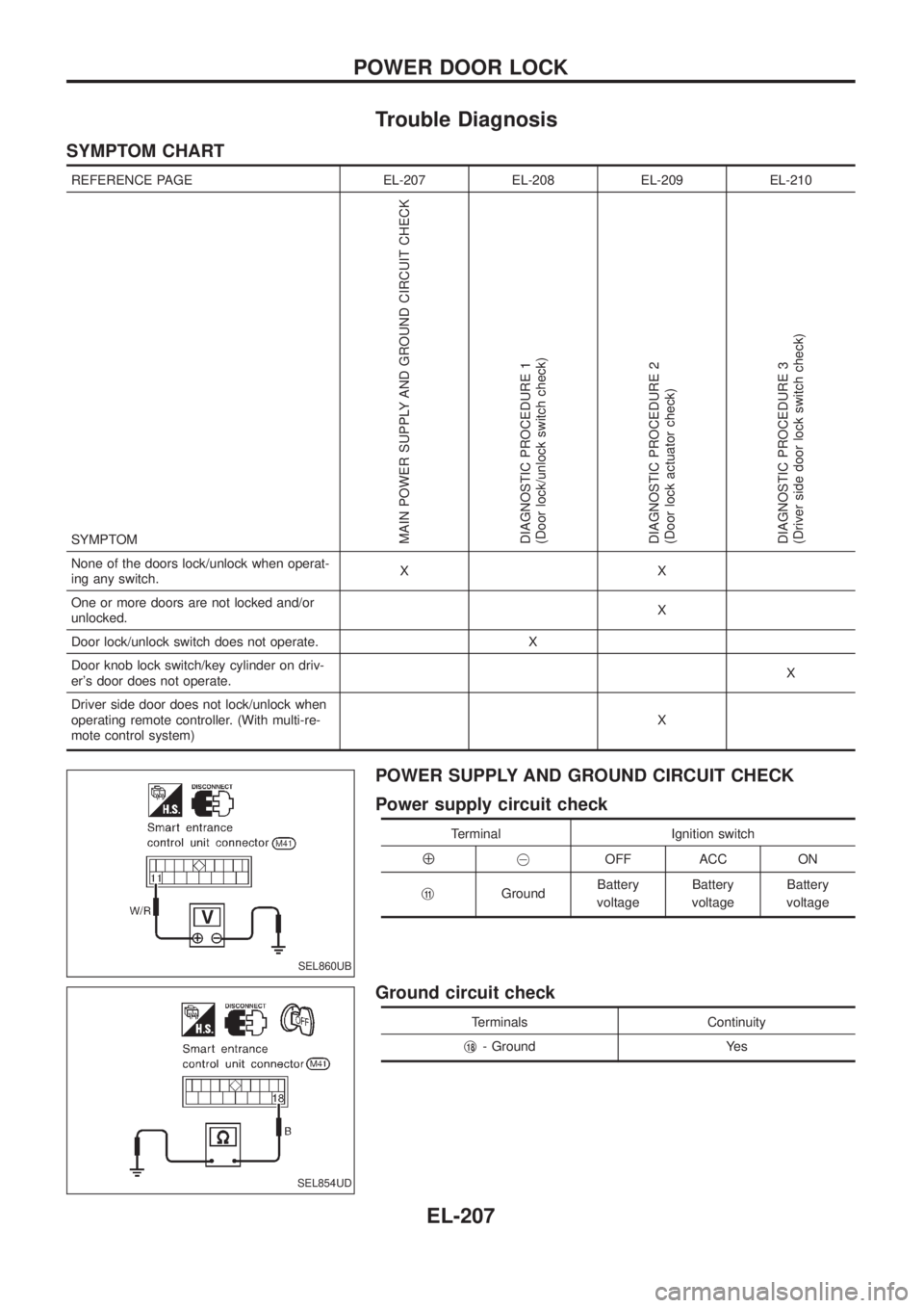
POWER SUPPLY AND GROUND CIRCUIT CHECK
Power supply circuit check
Terminal Ignition switch
Å@OFF ACC ON
j
11GroundBattery
voltageBattery
voltageBattery
voltage
Ground circuit check
Terminals Continuity
j
18- Ground Yes
SEL860UB
SEL854UD
POWER DOOR LOCK
EL-207
Page 555 of 1226
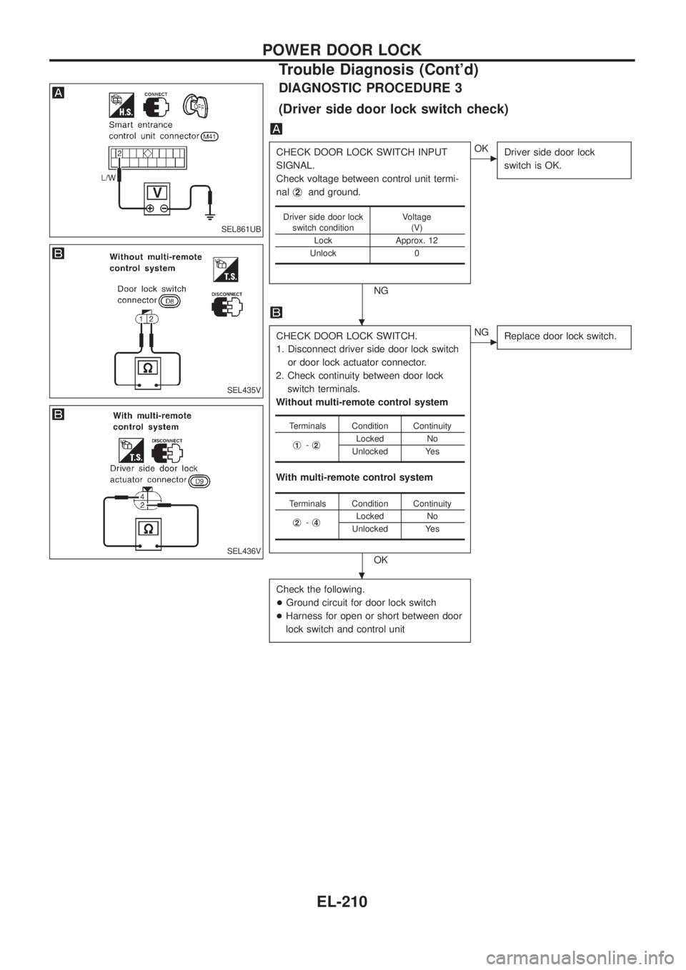
DIAGNOSTIC PROCEDURE 3
(Driver side door lock switch check)
CHECK DOOR LOCK SWITCH INPUT
SIGNAL.
Check voltage between control unit termi-
nalj
2and ground.
NG
cOK
Driver side door lock
switch is OK.
CHECK DOOR LOCK SWITCH.
1. Disconnect driver side door lock switch
or door lock actuator connector.
2. Check continuity between door lock
switch terminals.
Without multi-remote control system
With multi-remote control system
OK
cNG
Replace door lock switch.
Check the following.
+Ground circuit for door lock switch
+Harness for open or short between door
lock switch and control unit
Driver side door lock
switch conditionVoltage
(V)
Lock Approx. 12
Unlock 0
Terminals Condition Continuity
j
1-j2Locked No
Unlocked Yes
Terminals Condition Continuity
j
2-j4Locked No
Unlocked Yes
SEL861UB
SEL435V
SEL436V
.
.
POWER DOOR LOCK
Trouble Diagnosis (Cont'd)
EL-210
Page 557 of 1226
System Description
OUTLINE
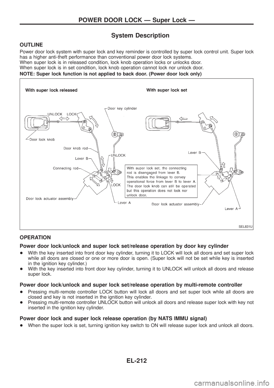
Power door lock system with super lock and key reminder is controlled by super lock control unit. Super lock
has a higher anti-theft performance than conventional power door lock systems.
When super lock is in released condition, lock knob operation locks or unlocks door.
When super lock is in set condition, lock knob operation cannot lock nor unlock door.
NOTE: Super lock function is not applied to back door. (Power door lock only)
OPERATION
Power door lock/unlock and super lock set/release operation by door key cylinder
+With the key inserted into front door key cylinder, turning it to LOCK will lock all doors and set super lock
while all doors are closed or one or more door is open. (Super lock will not be set while key is inserted
in the ignition key cylinder.)
+With the key inserted into front door key cylinder, turning it to UNLOCK will unlock all doors and release
super lock.
Power door lock/unlock and super lock set/release operation by multi-remote controller
+Pressing multi-remote controller LOCK button will lock all doors and set super lock while all doors are
closed and key is not inserted in the ignition key cylinder.
+Pressing multi-remote controller UNLOCK button will unlock all doors and release super lock with key not
inserted in the ignition key cylinder.
Power door lock and super lock release operation (by NATS IMMU signal)
+When the super lock is set, turning ignition key switch to ON will release super lock and unlock all doors.
SEL831U
POWER DOOR LOCK Ð Super Lock Ð
EL-212
Page 568 of 1226
Trouble Diagnoses
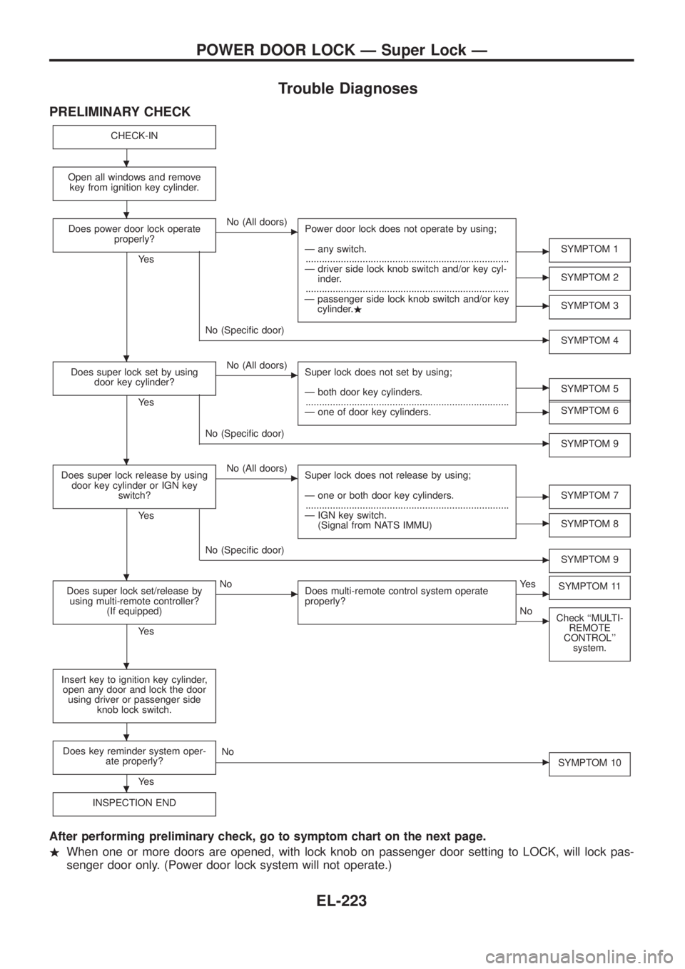
PRELIMINARY CHECK
CHECK-IN
Open all windows and remove
key from ignition key cylinder.
Does power door lock operate
properly?
Ye s
cNo (All doors)
Power door lock does not operate by using;
Ð any switch.
...........................................................................
Ð driver side lock knob switch and/or key cyl-
inder.
...........................................................................
Ð passenger side lock knob switch and/or key
cylinder..
cSYMPTOM 1
cSYMPTOM 2
cSYMPTOM 3
cNo (Speci®c door)
SYMPTOM 4
Does super lock set by using
door key cylinder?
Ye s
cNo (All doors)
Super lock does not set by using;
Ð both door key cylinders.
...........................................................................
Ð one of door key cylinders.
cSYMPTOM 5
cSYMPTOM 6
cNo (Speci®c door)
SYMPTOM 9
Does super lock release by using
door key cylinder or IGN key
switch?
Ye s
cNo (All doors)
Super lock does not release by using;
Ð one or both door key cylinders.
...........................................................................
Ð IGN key switch.
(Signal from NATS IMMU)
cSYMPTOM 7
cSYMPTOM 8
cNo (Speci®c door)
SYMPTOM 9
Does super lock set/release by
using multi-remote controller?
(If equipped)
Ye s
cNo
Does multi-remote control system operate
properly?cYe s
SYMPTOM 11
cNo
Check ``MULTI-
REMOTE
CONTROL''
system.
Insert key to ignition key cylinder,
open any door and lock the door
using driver or passenger side
knob lock switch.
Does key reminder system oper-
ate properly?
Ye s
cNo
SYMPTOM 10
INSPECTION END
After performing preliminary check, go to symptom chart on the next page.
.When one or more doors are opened, with lock knob on passenger door setting to LOCK, will lock pas-
senger door only. (Power door lock system will not operate.)
.
.
.
.
.
.
.
.
POWER DOOR LOCK Ð Super Lock Ð
EL-223
Page 569 of 1226
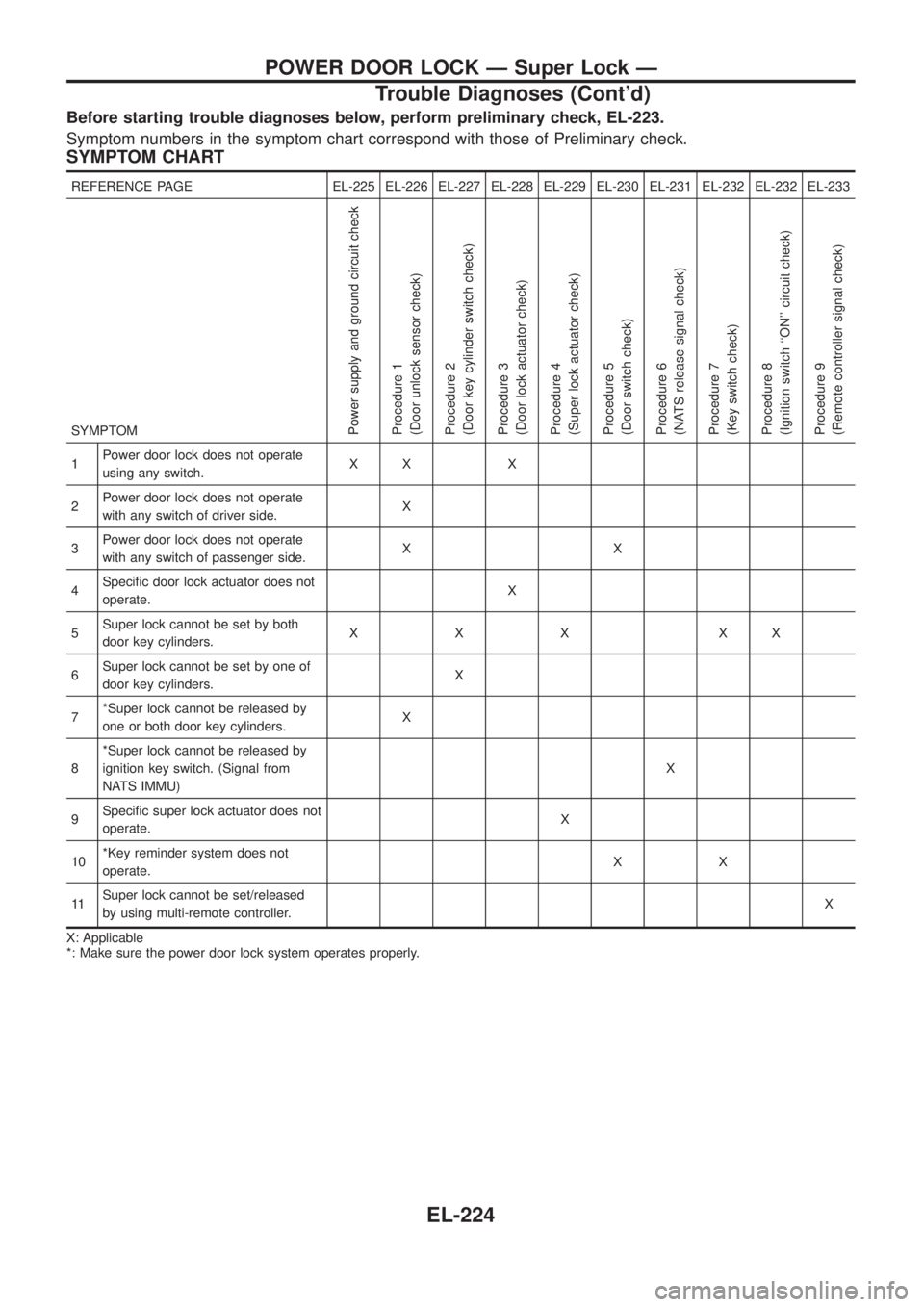
Before starting trouble diagnoses below, perform preliminary check, EL-223.
Symptom numbers in the symptom chart correspond with those of Preliminary check.
SYMPTOM CHART
REFERENCE PAGE EL-225 EL-226 EL-227 EL-228 EL-229 EL-230 EL-231 EL-232 EL-232 EL-233
SYMPTOM
Power supply and ground circuit check
Procedure 1
(Door unlock sensor check)
Procedure 2
(Door key cylinder switch check)
Procedure 3
(Door lock actuator check)
Procedure 4
(Super lock actuator check)
Procedure 5
(Door switch check)
Procedure 6
(NATS release signal check)
Procedure 7
(Key switch check)
Procedure 8
(Ignition switch ``ON'' circuit check)
Procedure 9
(Remote controller signal check)
1Power door lock does not operate
using any switch.XX X
2Power door lock does not operate
with any switch of driver side.X
3Power door lock does not operate
with any switch of passenger side.XX
4Speci®c door lock actuator does not
operate.X
5Super lock cannot be set by both
door key cylinders.XXX XX
6Super lock cannot be set by one of
door key cylinders.X
7*Super lock cannot be released by
one or both door key cylinders.X
8*Super lock cannot be released by
ignition key switch. (Signal from
NATS IMMU)X
9Speci®c super lock actuator does not
operate.X
10*Key reminder system does not
operate.XX
11Super lock cannot be set/released
by using multi-remote controller.X
X: Applicable
*: Make sure the power door lock system operates properly.
POWER DOOR LOCK Ð Super Lock Ð
Trouble Diagnoses (Cont'd)
EL-224
Page 578 of 1226
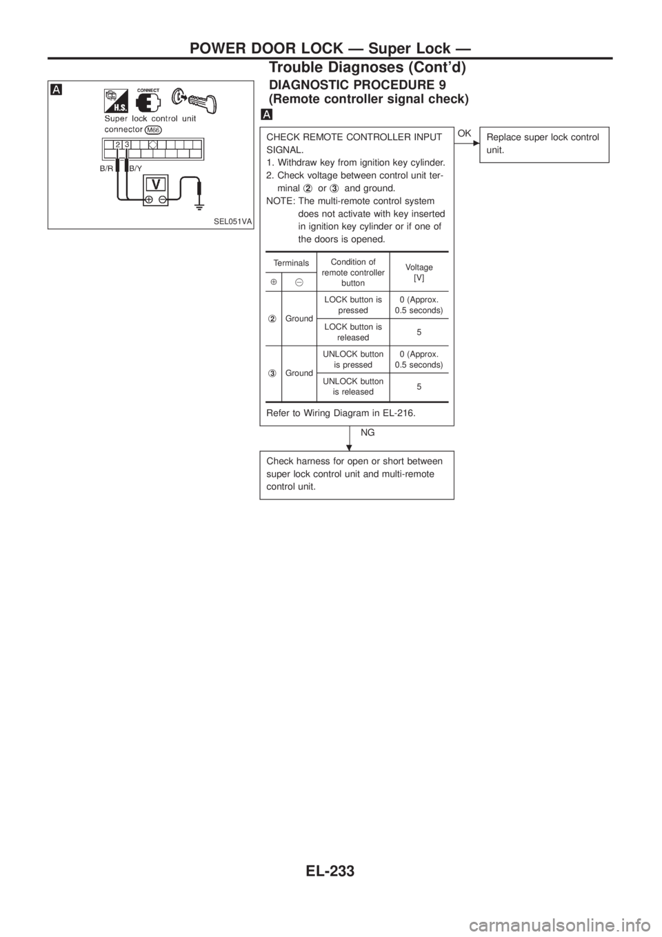
DIAGNOSTIC PROCEDURE 9
(Remote controller signal check)
CHECK REMOTE CONTROLLER INPUT
SIGNAL.
1. Withdraw key from ignition key cylinder.
2. Check voltage between control unit ter-
minalj
2orj3and ground.
NOTE: The multi-remote control system
does not activate with key inserted
in ignition key cylinder or if one of
the doors is opened.
Refer to Wiring Diagram in EL-216.
NG
cOK
Replace super lock control
unit.
Check harness for open or short between
super lock control unit and multi-remote
control unit.
TerminalsCondition of
remote controller
buttonVoltage
[V]
Å@
j
2GroundLOCK button is
pressed0 (Approx.
0.5 seconds)
LOCK button is
released5
j
3GroundUNLOCK button
is pressed0 (Approx.
0.5 seconds)
UNLOCK button
is released5
SEL051VA
.
POWER DOOR LOCK Ð Super Lock Ð
Trouble Diagnoses (Cont'd)
EL-233
Page 579 of 1226
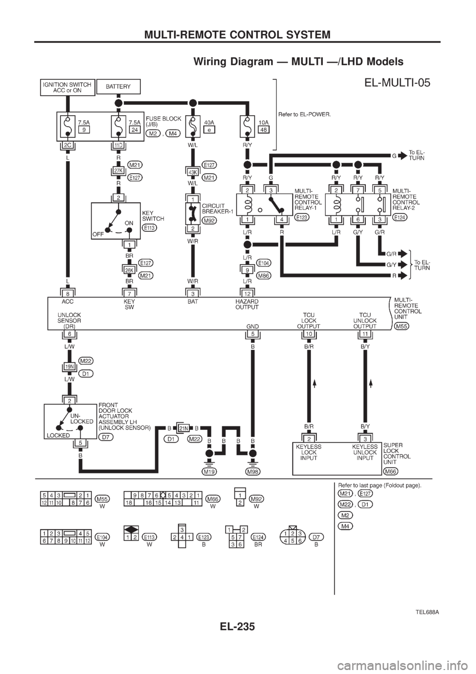
System Description
FUNCTION
Multi-remote control system has the following function.
+Door lock (and set super lock)
+Door unlock (and release super lock)
+Hazard reminder
LOCK OPERATION
To lock door by multi-remote controller, the following two signals must be received.
+Key switch OFF (when ignition key is not in ignition key cylinder.)
+All door switches CLOSED
When the LOCK signal is input to multi-remote control unit (the antenna of the system is combined with multi-
remote control unit), ground is supplied
+through multi-remote control unit terminalj
10
+to super lock control unit terminalj2.
Then super lock control unit operates to lock doors and set super lock.
UNLOCK OPERATION
To unlock door by multi-remote controller, the following signal must be received.
+Key switch OFF (when ignition key is not in ignition key cylinder)
When the UNLOCK signal is input to multi-remote control unit (the antenna of the system is combined with
multi-remote control unit), ground is supplied
+through multi-remote control unit terminalj
11
+to super lock control unit terminalj3.
Then super lock control unit operates to unlock doors and release super lock.
HAZARD REMINDER
When the doors are locked or unlocked by multi-remote controller, ground is supplied
+to terminalj
1of multi-remote control relay-1 and 2
+through multi-remote control unit terminalj
12.
Then the relays are energized and hazard warning lamp ¯ashes as follows
+Lock operation: Flash once
+Unlock operation: Flash twice
MULTI-REMOTE CONTROLLER ID CODE ENTRY
A maximum of four remote controllers can be entered. Any attempt to enter a remote controller will erase all
ID codes previously entered. Therefore, be sure to receive all remote controllers from the vehicle owner when
any ID code entry is performed.
To enter ID code entry, the following signals must be input to the multi-remote control unit.
+Driver side LOCKED signal (from driver side door unlock sensor)
+Door switch CLOSED signal
+Key switch signal (INSERTED/WITHDRAWN)
+Accessory power supply
+Signal from remote controller
For detailed procedure, refer to ``ID Code Entry Procedure'' in EL-239.
MULTI-REMOTE CONTROL SYSTEM
EL-234
Page 580 of 1226
Wiring Diagram Ð MULTI Ð/LHD Models
TEL688A
MULTI-REMOTE CONTROL SYSTEM
EL-235