check oil NISSAN PICK-UP 1998 Repair Manual
[x] Cancel search | Manufacturer: NISSAN, Model Year: 1998, Model line: PICK-UP, Model: NISSAN PICK-UP 1998Pages: 1659, PDF Size: 53.39 MB
Page 1210 of 1659

Rear Axle and Rear Suspension Parts
Check rear axle and rear suspension parts for excessive play,
wear or damage.
lShake each rear wheel to check for excessive play.
lRetighten all nuts and bolts to the specified torque.
: Refer to REAR SUSPENSION, RA-12..
lCheck shock absorber for oil leakage or other damage.
lCheck shock absorber bushing for excessive wear or other
damage.
Rear Wheel Bearing
lCheck that wheel bearings operate smoothly.
lCheck axial end play.
Axial end play:
Refer to SDS, RA-15.
SMA525A
SRA839
SRA734
SRA006-A
ON-VEHICLE SERVICE
RA-4
Page 1217 of 1659
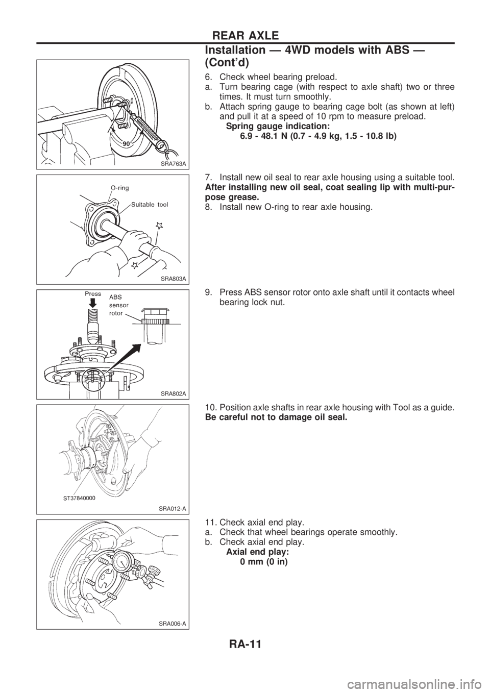
6. Check wheel bearing preload.
a. Turn bearing cage (with respect to axle shaft) two or three
times. It must turn smoothly.
b. Attach spring gauge to bearing cage bolt (as shown at left)
and pull it at a speed of 10 rpm to measure preload.
Spring gauge indication:
6.9 - 48.1 N (0.7 - 4.9 kg, 1.5 - 10.8 lb)
7. Install new oil seal to rear axle housing using a suitable tool.
After installing new oil seal, coat sealing lip with multi-pur-
pose grease.
8. Install new O-ring to rear axle housing.
9. Press ABS sensor rotor onto axle shaft until it contacts wheel
bearing lock nut.
10. Position axle shafts in rear axle housing with Tool as a guide.
Be careful not to damage oil seal.
11. Check axial end play.
a. Check that wheel bearings operate smoothly.
b. Check axial end play.
Axial end play:
0mm(0in)
SRA763A
SRA803A
SRA802A
SRA012-A
SRA006-A
REAR AXLE
Installation Ð 4WD models with ABS Ð
(Cont'd)
RA-11
Page 1220 of 1659
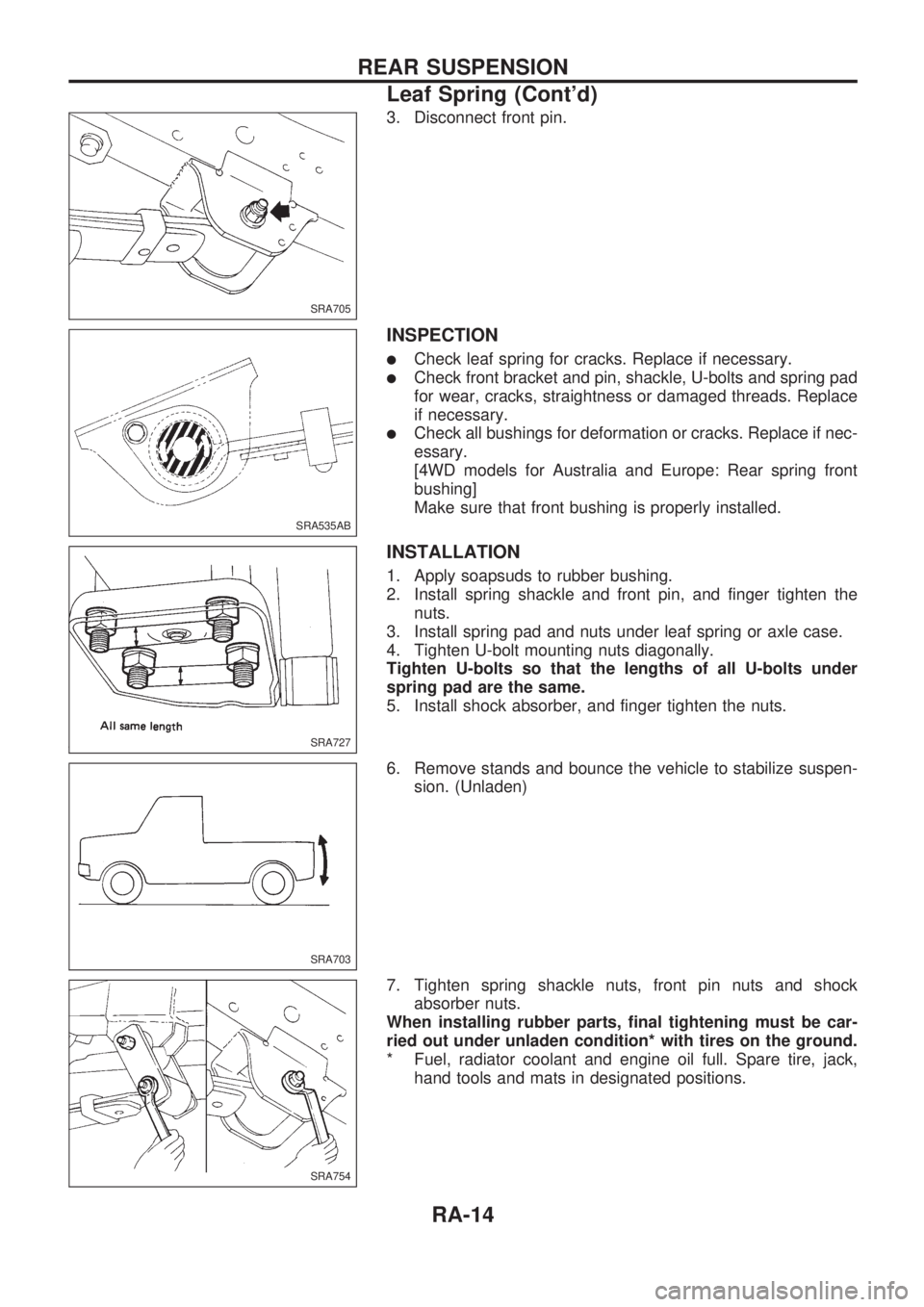
3. Disconnect front pin.
INSPECTION
lCheck leaf spring for cracks. Replace if necessary.
lCheck front bracket and pin, shackle, U-bolts and spring pad
for wear, cracks, straightness or damaged threads. Replace
if necessary.
lCheck all bushings for deformation or cracks. Replace if nec-
essary.
[4WD models for Australia and Europe: Rear spring front
bushing]
Make sure that front bushing is properly installed.
INSTALLATION
1. Apply soapsuds to rubber bushing.
2. Install spring shackle and front pin, and finger tighten the
nuts.
3. Install spring pad and nuts under leaf spring or axle case.
4. Tighten U-bolt mounting nuts diagonally.
Tighten U-bolts so that the lengths of all U-bolts under
spring pad are the same.
5. Install shock absorber, and finger tighten the nuts.
6. Remove stands and bounce the vehicle to stabilize suspen-
sion. (Unladen)
7. Tighten spring shackle nuts, front pin nuts and shock
absorber nuts.
When installing rubber parts, final tightening must be car-
ried out under unladen condition* with tires on the ground.
* Fuel, radiator coolant and engine oil full. Spare tire, jack,
hand tools and mats in designated positions.
SRA705
SRA535AB
.
SRA727
SRA703
SRA754
REAR SUSPENSION
Leaf Spring (Cont'd)
RA-14
Page 1222 of 1659

STEERING SYSTEM
SECTIONST
CONTENTS
PRECAUTIONS AND PREPARATION..................... 1
Supplemental Restraint System (SRS) ``AIR
BAG'' (4WD models).............................................. 1
Supplemental Restraint System (SRS) ``AIR
BAG'' (2WD models).............................................. 1
Precautions for Steering System ........................... 1
Special Service Tools ............................................ 2
ON-VEHICLE SERVICE............................................ 4
Steering System..................................................... 4
Checking and Adjusting Drive Belts (For
power steering) ...................................................... 4
Checking Fluid Level (For power steering) ........... 4
Checking Fluid Leakage (For power steering) ...... 5
Bleeding Hydraulic System (For power
steering) ................................................................. 5
Checking Steering Wheel Turning Force (For
power steering) ...................................................... 6
Checking Steering Wheel Play .............................. 6
Checking Neutral Position on Steering Wheel ...... 7
Checking Front Wheel Turning Angle ................... 7
Checking Hydraulic System (For power
steering) ................................................................. 7
STEERING WHEEL AND STEERING COLUMN..... 9
Steering Wheel ...................................................... 9
Steering Column .................................................. 10
Disassembly and Assembly ................................. 11
Inspection ............................................................. 12
MANUAL STEERING GEAR (Model: VB66K)....... 13
Removal and Installation ..................................... 13
Disassembly ......................................................... 14
Assembly and Adjustment ................................... 14Inspection ............................................................. 17
POWER STEERING SYSTEM (Model: PB48S)..... 19
Description ........................................................... 19
POWER STEERING GEAR (Model: PB48S)......... 20
Removal and Installation ..................................... 20
Power Steering Gear Component ....................... 20
Pre-disassembly Inspection and Adjustment....... 21
Disassembly ......................................................... 22
Assembly.............................................................. 24
POWER STEERING SYSTEM (Model: PB59K).... 27
Description ........................................................... 27
POWER STEERING GEAR (Model: PB59K)......... 28
Removal and Installation ..................................... 28
Power Steering Gear Component ....................... 28
Pre-disassembly Inspection and Adjustment....... 29
Disassembly ......................................................... 30
Assembly.............................................................. 31
POWER STEERING OIL PUMP.............................. 34
Disassembly and Assembly ................................. 34
Pre-disassembly Inspection ................................. 34
Inspection ............................................................. 35
Disassembly ......................................................... 35
Assembly.............................................................. 36
STEERING LINKAGE.............................................. 37
Removal and Installation ..................................... 37
Disassembly ......................................................... 38
Inspection ............................................................. 39
SERVICE DATA AND SPECIFICATIONS (SDS)... 40
General Specifications ......................................... 40
Inspection and Adjustment .................................. 40
ST
Page 1229 of 1659
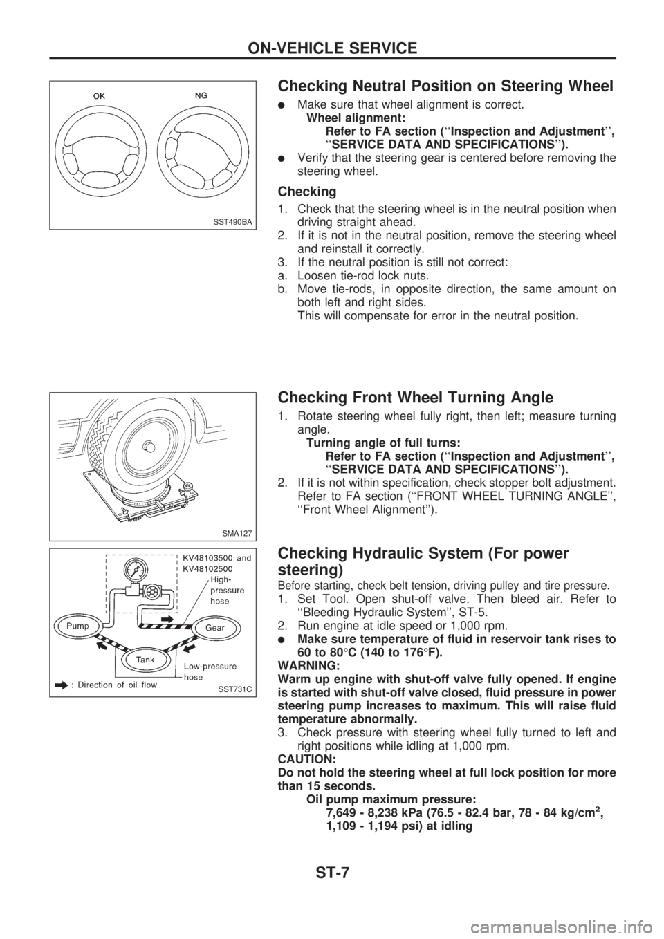
Checking Neutral Position on Steering Wheel
lMake sure that wheel alignment is correct.
Wheel alignment:
Refer to FA section (``Inspection and Adjustment'',
``SERVICE DATA AND SPECIFICATIONS'').
lVerify that the steering gear is centered before removing the
steering wheel.
Checking
1. Check that the steering wheel is in the neutral position when
driving straight ahead.
2. If it is not in the neutral position, remove the steering wheel
and reinstall it correctly.
3. If the neutral position is still not correct:
a. Loosen tie-rod lock nuts.
b. Move tie-rods, in opposite direction, the same amount on
both left and right sides.
This will compensate for error in the neutral position.
Checking Front Wheel Turning Angle
1. Rotate steering wheel fully right, then left; measure turning
angle.
Turning angle of full turns:
Refer to FA section (``Inspection and Adjustment'',
``SERVICE DATA AND SPECIFICATIONS'').
2. If it is not within specification, check stopper bolt adjustment.
Refer to FA section (``FRONT WHEEL TURNING ANGLE'',
``Front Wheel Alignment'').
Checking Hydraulic System (For power
steering)
Before starting, check belt tension, driving pulley and tire pressure.
1. Set Tool. Open shut-off valve. Then bleed air. Refer to
``Bleeding Hydraulic System'', ST-5.
2. Run engine at idle speed or 1,000 rpm.
lMake sure temperature of fluid in reservoir tank rises to
60 to 80ÉC (140 to 176ÉF).
WARNING:
Warm up engine with shut-off valve fully opened. If engine
is started with shut-off valve closed, fluid pressure in power
steering pump increases to maximum. This will raise fluid
temperature abnormally.
3. Check pressure with steering wheel fully turned to left and
right positions while idling at 1,000 rpm.
CAUTION:
Do not hold the steering wheel at full lock position for more
than 15 seconds.
Oil pump maximum pressure:
7,649 - 8,238 kPa (76.5 - 82.4 bar, 78 - 84 kg/cm
2,
1,109 - 1,194 psi) at idling
SST490BA
SMA127
SST731C
ON-VEHICLE SERVICE
ST-7
Page 1238 of 1659
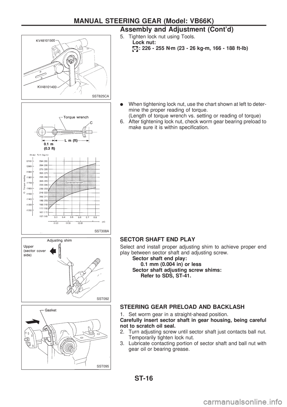
5. Tighten lock nut using Tools.
Lock nut:
: 226 - 255 Nzm (23 - 26 kg-m, 166 - 188 ft-lb)
lWhen tightening lock nut, use the chart shown at left to deter-
mine the proper reading of torque.
(Length of torque wrench vs. setting or reading of torque)
6. After tightening lock nut, check worm gear bearing preload to
make sure it is within specification.
SECTOR SHAFT END PLAY
Select and install proper adjusting shim to achieve proper end
play between sector shaft and adjusting screw.
Sector shaft end play:
0.1 mm (0.004 in) or less
Sector shaft adjusting screw shims:
Refer to SDS, ST-41.
STEERING GEAR PRELOAD AND BACKLASH
1. Set worm gear in a straight-ahead position.
Carefully insert sector shaft in gear housing, being careful
not to scratch oil seal.
2. Turn adjusting screw until sector shaft just contacts ball nut.
Temporarily tighten lock nut.
3. Lubricate contacting portion of sector shaft and ball nut with
gear oil or bearing grease.
SST825CA
SST308A
SST092
SST095
MANUAL STEERING GEAR (Model: VB66K)
Assembly and Adjustment (Cont'd)
ST-16
Page 1240 of 1659
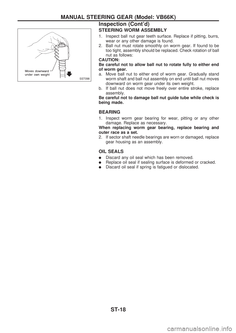
STEERING WORM ASSEMBLY
1. Inspect ball nut gear teeth surface. Replace if pitting, burrs,
wear or any other damage is found.
2. Ball nut must rotate smoothly on worm gear. If found to be
too tight, assembly should be replaced. Check rotation of ball
nut as follows:
CAUTION:
Be careful not to allow ball nut to rotate fully to either end
of worm gear.
a. Move ball nut to either end of worm gear. Gradually stand
worm shaft and ball nut assembly on end until ball nut moves
downward on worm gear under its own weight.
b. If ball nut does not move freely over entire stroke, replace
assembly.
Be careful not to damage ball nut guide tube while check is
being made.
BEARING
1. Inspect worm gear bearing for wear, pitting or any other
damage. Replace as necessary.
When replacing worm gear bearing, replace bearing and
outer race as a set.
2. If sector shaft needle bearings are worn or damaged, replace
gear housing as an assembly.
OIL SEALS
lDiscard any oil seal which has been removed.
lReplace oil seal if sealing surface is deformed or cracked.
lDiscard oil seal if spring is fatigued or dislocated.
SST098
MANUAL STEERING GEAR (Model: VB66K)
Inspection (Cont'd)
ST-18
Page 1243 of 1659
Pre-disassembly Inspection and Adjustment
Before disassembling power steering gear component
parts, make sure there is no oil leakage around sealing por-
tion and check steering turning torque as follows:
Check sealing portion.
lAdjusting screw nut O-ring
lSector shaft cover O-ring
lSector shaft oil seal
lRear cover oil seal and O-ring
lRear housing O-ring
lGear housing O-ring
Discard any oil seal and O-ring which have been removed.
Replace oil seal and O-ring if sealing surface is deformed or
cracked.
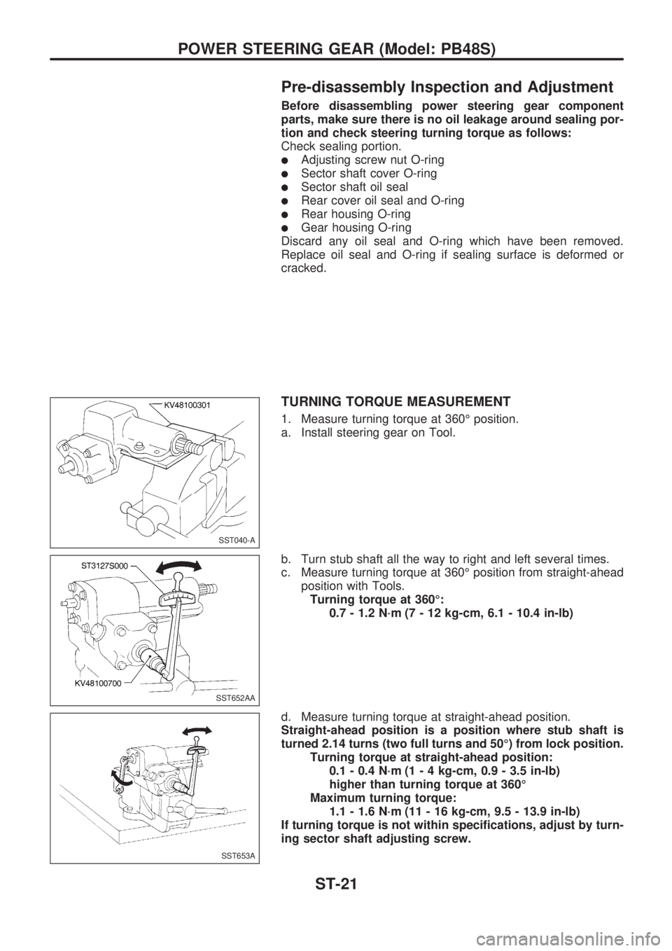
TURNING TORQUE MEASUREMENT
1. Measure turning torque at 360É position.
a. Install steering gear on Tool.
b. Turn stub shaft all the way to right and left several times.
c. Measure turning torque at 360É position from straight-ahead
position with Tools.
Turning torque at 360É:
0.7 - 1.2 N´m (7 - 12 kg-cm, 6.1 - 10.4 in-lb)
d. Measure turning torque at straight-ahead position.
Straight-ahead position is a position where stub shaft is
turned 2.14 turns (two full turns and 50É) from lock position.
Turning torque at straight-ahead position:
0.1 - 0.4 N´m (1 - 4 kg-cm, 0.9 - 3.5 in-lb)
higher than turning torque at 360É
Maximum turning torque:
1.1 - 1.6 N´m (11 - 16 kg-cm, 9.5 - 13.9 in-lb)
If turning torque is not within specifications, adjust by turn-
ing sector shaft adjusting screw.
SST040-A
SST652AA
SST653A
POWER STEERING GEAR (Model: PB48S)
ST-21
Page 1248 of 1659
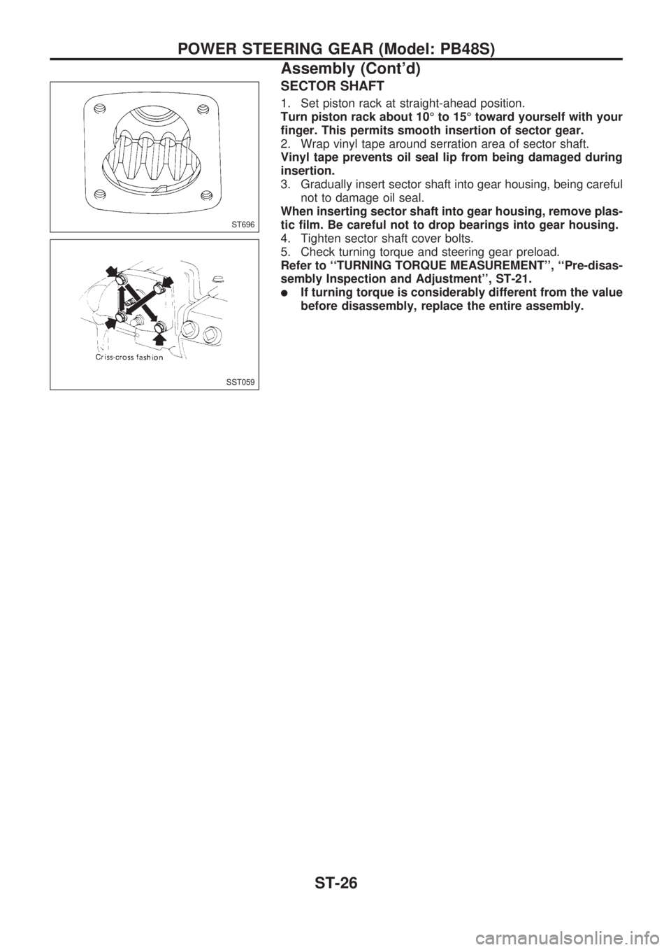
SECTOR SHAFT
1. Set piston rack at straight-ahead position.
Turn piston rack about 10É to 15É toward yourself with your
finger. This permits smooth insertion of sector gear.
2. Wrap vinyl tape around serration area of sector shaft.
Vinyl tape prevents oil seal lip from being damaged during
insertion.
3. Gradually insert sector shaft into gear housing, being careful
not to damage oil seal.
When inserting sector shaft into gear housing, remove plas-
tic film. Be careful not to drop bearings into gear housing.
4. Tighten sector shaft cover bolts.
5. Check turning torque and steering gear preload.
Refer to ``TURNING TORQUE MEASUREMENT'', ``Pre-disas-
sembly Inspection and Adjustment'', ST-21.
lIf turning torque is considerably different from the value
before disassembly, replace the entire assembly.
ST696
SST059
POWER STEERING GEAR (Model: PB48S)
Assembly (Cont'd)
ST-26
Page 1251 of 1659

Pre-disassembly Inspection and Adjustment
Before disassembling power steering gear component
parts, make sure there is no oil leakage around sealing por-
tion and check steering turning torque as follows:
Check sealing portion.
lSector shaft cover O-ring
lSector shaft U-packing
lSector shaft oil seal
lRear housing O-ring
lGear housing O-ring
Discard any oil seal and O-ring which have been removed.
Replace oil seal and O-ring if sealing surface is deformed or
cracked.
TURNING TORQUE MEASUREMENT
1. Measure turning torque at 360É position.
a. Install steering gear on Tool.
b. Turn stub shaft all the way to right and left several times.
c. Measure turning torque at 360É position from straight-ahead
position with Tools.
Turning torque at 360É:
0.15 - 0.78 N´m (1.5 - 8.0 kg-cm, 1.3 - 6.9 in-lb)
d. Measure turning torque at straight-ahead position.
Straight-ahead position is a position where stub shaft is
turned 2.14 turns (two full turns and 50É) from lock position.
Turning torque at straight-ahead position:
0.2 - 0.5 N´m (2 - 5 kg-cm, 1.7 - 4.3 in-lb)
higher than turning torque at 360É
Maximum turning torque:
0.44 - 1.18 N´m (4.5 - 12 kg-cm, 3.9 - 10.4 in-lb)
If turning torque is not within specifications, adjust by turn-
ing sector shaft adjusting screw.
SST040-A
SST652AA
SST653A
POWER STEERING GEAR (Model: PB59K)
ST-29